
6 Monitoring
Part 2
Reference voltages in audio signals
We wrote in Part 1 of this chapter about electrical measurements using VU meters and PPMs, but avoided any mention of the units to be used. This matter should be cleared up before we go any further.
We don't want to make the following part heavy going for those readers who are ‘serious amateurs’ in the audio world, such as teachers. It is included because there may be readers who are going to use professional, or even semi-professional, equipment which is fitted with decent metering, and to make proper use of it the information here may be very helpful. It might be a good idea to skim over the next part fairly quickly, but be prepared to read it more thoroughly if the need arises.
Technical monitoring could use volts, or millivolts, or any other electrical unit. However, it is generally most convenient to use a decibel scale. That raises the question, ‘Decibels relative to what?’ A zero based on the dB(A) (Chapter 2) would be impracticable because the dB(A) is an acoustic unit, whereas here we are concerned with finding an electrical basis for measurement.
It has been the more or less universal practice for many years to take as a reference voltage a value of 0.775 V, and call this 0 dB or zero level. The number 0.775, which seems curious, in fact has a historical background. In the early days of broadcasting and telephony, both in the UK and elsewhere, a useful standard for audio systems was deemed to be a power of 1 mW (1 milliwatt). This could be handled by quite modest little amplifiers and cables, but was at the same time a high enough power for this level of signal not to be susceptible to interference from adjacent circuitry. A standard resistance (strictly we should say impedance) was also adopted, namely 600 ohms, this being apparently the typical value for a pair of conventional telephone wires of considerable length.
It is not very easy to measure powers such as a milliwatt, but voltage measurements are much simpler. Thus, voltage measurements across, in this case, 600 ohms, can be equivalent to power measurements. The reader may well remember that power, voltage and current are related. Here we make use of the fact that power = (voltage)2/resistance.
Now 1 mW is 0.001 W and the resistance is 600 Ω (Ω means ohms), so inserting these:
0.001 = |
(voltage)2/resistance |
i.e. (voltage)2 = |
0.001 × (resistance) |
or V2 = |
0.001 × 600 |
so that V2 = |
0.6 |
and V = |
|
making V = |
0.775 QED |
Hence, provided all significant resistances were 600 Ω, simple voltage measurements enabled an engineer to calculate the power if he needed to. In more recent years it has not been necessary to make all important resistances 600 Ω and the notion of 1 mW as a standard power has gradually been dropped. All that remains is the standard voltage of 0.775 V and this is referred to as ‘zero level’.
PPMs and VU meter readings
The photograph of a PPM (Figure 6.2) shows that its scale is numbered 1 to 7. These are arbitrary units but are related to the signal level in the way shown in Table 6.1.
It will be seen that there are 4 dB between the divisions and one of the advantages of the PPM is that since pointer deflection is proportional to the level in dBs, it relates approximately to perceived changes in loudness. This is not to say that the PPM is a satisfactory loudness meter – it is not, for the very good reason that it does not make allowances for the way in which the ear's sensitivity varies with frequency.
A VU meter scale (see Figure 6.1) is marked in dB but suffers from the fact that the dB readings are unevenly spaced, being cramped at the lower end. What is often confusing is that the ‘0’ on a VU scale does not represent zero level. The modern convention is that it indicates +4 dB above zero level. Unfortunately, different manufacturers seem to adopt slightly different VU meter standards, so that the user may be advised to let the pointer exceed ‘0’ (into the region where the scale is coloured red) for a proportion of the time.
PPM |
dB relative to zero level |
Voltage |
1 |
-12 |
0.19 |
2 |
-8 |
0.31 |
3 |
4 |
0.49 |
4 |
0 (zero level) |
0.775 |
5 |
+4 |
1.23 |
6 |
+8 |
1.96 |
7 |
+12 |
3.08 |
Some VU meters have two scales, one in dB and the other in percentages, where the ‘0’ is also labelled 100%.
PPM reading ‘6’ is regarded as the maximum signal level which can be allowed and there is a risk of distortion somewhere in the succeeding chain of equipment if ‘6’ is exceeded.
Two things are worth noting:
1. The peak permissible level (i.e. PPM 6) is 8 dB above zero level.
2. The voltage corresponding to this peak is 2.5 times 0.775 V. Or, putting things slightly differently, zero level is 40% of the peak voltage.
Helmholtz resonators
These are particularly interesting acoustic devices and have many uses. They are mentioned here because of their application to vented enclosure loudspeakers. The basic form is shown in Figure 6.7.
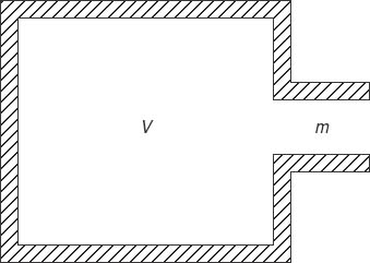
Figure 6.7 Basic Helmholtz resonator
Named after Hermann von Helmholtz (1821–1894), who may have discovered the effect, the action is that the mass (m) of air in the neck corresponds to a weight on a spring, the spring in this case being provided by the compliance of the volume of air (V) in the body. Just as a weight on the end of a spring can oscillate up and down, so can the air in the neck oscillate. It might seem that the mass of air in the neck is too small to have any significance, but it must be remembered that the air in the body is a very ‘weak’ spring.
The resonant frequency of a resonator of this type is given approximately by the formula below. (As always with formulae, consistency in the units is essential. If A is in (metres)2 then the volume must be in (metres)3, and so on.)
f = 54![]() A/lV
A/lV
where A is the cross-sectional area of the neck, l is the length of the neck and V is the volume of the body.
Of great value in many aspects of acoustics is the fact that low resonant frequencies can be obtained with Helmholtz resonators of relatively small size. If there is some substance in the neck which can provide enough friction to the air movements (gauze for instance), the device becomes a sound absorber at its resonant frequency. If there is only a little friction then it can re-radiate sound. Clearly, getting the right amount of friction in the neck is critical in designing a good vented loudspeaker.
Gin and whisky bottles (empty of course!) are good Helmholtz resonators. Blowing across the neck excites the natural resonant frequency, which is typically around 110 Hz for 70 cl bottles. The scientifically minded reader who measures the internal dimensions of a whisky bottle and then applies the formula given above mustn't be too surprised if calculation fails to agree with any measurements. One reason is that the acoustic length of a tube – in this case the bottle's neck – is always greater than the physical length!
Loudspeaker power
There is an unfortunate tendency for those who take advertisements at their face value to believe that the higher the power rating of a loudspeaker, the better the quality of reproduction from it. Thus, it might be supposed by some that a 100 W loudspeaker is twice as good as one rated at 50 W. The simple fact is that the only information the power rating gives is how much electrical power can be fed into it without damaging it, or at least causing distortion. There is no automatic guarantee that the higher powered of two units will produce the better output, or even the louder output.
Table 6.2 Specifications of an acceptably good small loudspeaker
Height |
300 mm |
Width |
200 mm |
Depth |
160 mm |
Frequency response |
60 Hz to 15 kHz |
Maximum input power |
25 W |
Max. sound pressure level at 1 m |
90 dB(A) |
The efficiency of a loudspeaker is low – that is, the proportion of sound power coming out compared to the electrical power fed in is small. The efficiency of a high-grade monitoring speaker may be only 1–2%, so that for every (say) 100 W fed in only 1 or 2 W of acoustic power emerge, the remaining 98–99 W appearing as heat. Generally, the better the loudspeaker the lower its efficiency, so that a good quality loudspeaker rated at 100 W may actually produce no more noise than a less good one rated at 50 W.
Loudspeaker cables
Over recent years there have been available on the market some very expensive cables for connecting loudspeakers to amplifiers. It is pretty safe to say that properly conducted tests of the A–B type have shown them to have no advantages over conventional cables of adequate current rating. It is clear that a connecting cable must have a total resistance (i.e. in both conductors) which is much less than the impedance of the loudspeaker, otherwise power is wasted in the cable. The situation is complicated by the fact that the impedance of a loudspeaker can vary widely with frequency but is likely at some frequencies to be greater rather than less than the stated figure. Thus, an 8 Ω speaker will probably have an impedance of around 8 Ω over much of the range, but becoming greater over a narrow band. So, if the cable for this unit has a resistance of 1 Ω or less there should not be excessive loss in it.
As an example, a typical 13 A mains cable has a resistance of about 20 Ω/km in each conductor. Since there are two conductors, a 10 m run of this cable will have a total resistance of roughly 40/100 = 0.4 Ω, which is very small compared with the probable loudspeaker impedance. For most applications, cable rated at 10 A will be adequate.
If there are very long cable runs, it may be worthwhile using a system known as 100-volt working (see Part 2 of Chapter 12).
Professional and domestic standards
Finally, it is important to make clear one important difference between professional and domestic equipment in regard to signal levels. The reader will have gathered from what has been said here that the standard level (‘zero level’) adopted in professional equipment is 0 dB (= 0.775 V). Almost all domestic, and indeed some semi-professional equipment, adopts –10 dB (0.25 V) as the reference. This is of no consequence unless there is a mixture of the two types of equipment, and even then any difficulties can be overcome. It is best, though, to be forewarned.
Questions
1. On a standard PPM, what meter reading is taken as the maximum signal level if distortion is to be avoided?
a. 4 |
b. 6 |
c. 7 |
d. 8 |
2. What is the likely electrical efficiency of a high-grade monitoring loudspeaker?
a. 0.1% |
b. 0.5% |
c. 1–2% |
d. 10% |
e. 50% |