
Super-Lift Converter Multilevel DC/AC Inverters Used in Solar Panel Energy Systems
Super-lift converter multilevel DC/AC inverters will be introduced in this chapter. For convenience, we call them super-lift inverters or SL inverters (SLIs).
The super-lift technique is the most outstanding contribution in DC/DC conversion technology [1,2,3,4]. Positive output super-lift Luo converters can easily lift the DC input voltage into a higher-level output DC voltage. In addition, positive output super-lift Luo converters have many subseries and circuits. The voltage transfer gains of the circuits increase in geometrical series (power series) stage by stage. Therefore, the super-lift technique has attracted much worldwide attention in recent decades. We were the first to apply super-lift Luo converters in DC/AC inverters.
An elementary positive output super-lift Luo converter is shown in Figure 11.1a. The equivalent circuits are shown in Figure 11.1b when switch S is on and Figure 11.1c when switch S is off.
When the main switch S is on, the inductor L1 and capacitor C 1 are charged by the source voltage Vin. In the steady state, VC1 = Vin. When the main switch S is off, the output voltage VO is highly lifted from source voltage by inductor L1 and capacitor C1, as can be seen from the following equation
(11.1) |
where k is the duty cycle. A re-lift positive output super-lift Luo converter is shown in Figure 11.2.
Its output voltage VO is
(11.2) |
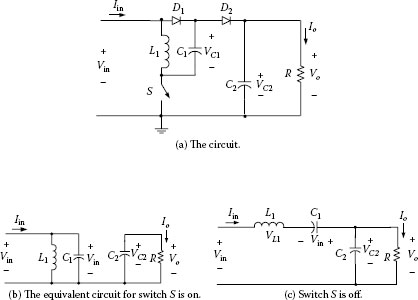
FIGURE 11.1
Elementary circuit of a positive output super-lift Luo converter.
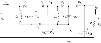
FIGURE 11.2
Re-lift circuit of the positive output super-lift Luo converter.
11.2 Super-Lift Converter Used in Multilevel DC/AC Inverters
In this section, we show how to apply the super-lift conversion technique in multilevel DC/AC inverters.
11.2.1 Seven-Level SL Inverter
A seven-level super-lift inverter is shown in Figure 11.3.
There is only one DC voltage source E needed in this circuit. A change-over-switch (2P2T) and a three-position band-switch are used in the circuit. When k = 0.5, the output voltage is 3E. Three capacitors, C2, C3, and C4, are used to split the output voltage in 3 levels: E, 2E, and 3E. Therefore, the operation status is as follows:
• Vout = 3E: The change-over-switch is on, and the band-switch is at position 3.
• Vout = 2E: The change-over-switch is on, and the band-switch is at position 2.
• Vout = E: The change-over-switch is on, and the band-switch is at position 1.
• Vout = 0: The band-switch is at position 0 (i.e., N).
• Vout = −E: The change-over-switch is off, and the band-switch is at position 1.
• Vout = −2E: The change-over-switch is off, and the band-switch is at position 2.
• Vout = −3E: The change-over-switch is off, and the band-switch is at position 3.
We have obtained a seven-level output AC voltage. The output voltage peak value is three times the input DC voltage E. The waveform is shown in Figure 11.4.
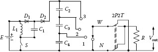
FIGURE 11.3
A seven-level super-lift inverter.
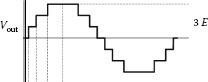
FIGURE 11.4
Seven-level waveform.
11.2.2 Fifteen-Level SL Inverter
A 15-level super-lift inverter is shown in Figure 11.5.
One change-over-switch (2P2T) is used in the circuit. When k = 6/7 (≈ 0.857), the output voltage is 7E. We use seven capacitors, C2, C3, C4, C5 C6, C7 and C8, to split the output voltage in seven levels: E, 2E, 3E, 4E, 5E, 6E, and 7E. Therefore, the operation status is as follows:
• Vout = 7E: The change-over-switch is on, and the band-switch is at position 7
• Vout = 6E: The change-over-switch is on, and the band-switch is at position 6.
• Vout = 5E: The change-over-switch is on, and the band-switch is at position 5.
• Vout = 4E: The change-over-switch is on, and the band-switch is at position 4.
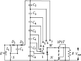
FIGURE 11.5
A fifteen-level super-lift inverter.
• Vout = 3E: The change-over-switch is on, and the band-switch is at position 3.
• Vout = 2E: The change-over-switch is on, and the band-switch is at position 2.
• Vout = E: The change-over-switch is on, and the band-switch is at position 1.
• Vout = 0: The band-switch is at position 0 (i.e., N).
• Vout = −E: The change-over-switch is off, and the band-switch is at position 1.
• Vout = −2E: The change-over-switch is off, and the band-switch is at position 2.
• Vout = −3E: The change-over-switch is off, and the band-switch is at position 3.
• Vout = −4E: The change-over-switch is off, and the band-switch is at position 4.
• Vout = −5E: The change-over-switch is off, and the band-switch is at position 5.
• Vout = −6E: The change-over-switch is off, and the band-switch is at position 6.
• Vout = −7E: The change-over-switch is off, the band-switch is at position 7.
We have obtained a 15-level output AC voltage. The output voltage peak value is seven times the input DC voltage E. The waveform is shown in Figure 11.6.
11.2.3 Twenty-One-Level SC Inverter
A positive output re-lift super-lift Luo converter is used to construct a 21-level inverter. Its circuit diagram is shown in Figure 11.7. A change-over switch (2P2T) is used in the circuit.
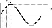
FIGURE 11.6
A fifteen-level waveform.
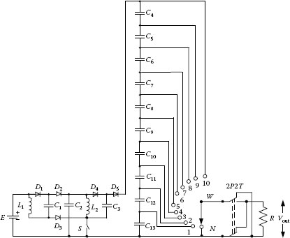
FIGURE 11.7
A 21-level super-lift inverter.
When (k ≈ 0.54), the output voltage is 10E. We use 10 capacitors, C4, C5, C6, C7 C8, C9, C10, C11, C12, and C13, to split the output voltage in 10 levels: E, 2E, 3E, 4E, 5E, 6E, 7E, 8E, 9E, and 10E. Therefore, the operation status is as follows:
• Vout = 10E: The change-over-switch is on, and the band-switch is at position 10.
• Vout = 9E: The change-over-switch is on, and the band-switch is at position 9.
• Vout = 8E: The change-over-switch is on, and the band-switch is at position 8.
• Vout = 7E: The change-over-switch is on, and the band-switch is at position 7.
• Vout = 6E: The change-over-switch is on, and the band-switch is at position 6.
• Vout = 5E: The change-over-switch is on, and the band-switch is at position 5.
• Vout = 4E: The change-over-switch is on, and the band-switch is at position 4.
• Vout = 3E: The change-over-switch is on, and the band-switch is at position 3.
• Vout = 2E: The change-over-switch is on, and the band-switch is at position 2.
• Vout = E: The change-over-switch is on, and the band-switch is at position 1.
• Vout = 0: The band-switch is at position 0 (i.e., N).
• Vout = −E: The change-over-switch is off, and the band-switch is at position 1.
• Vout = −2E: The change-over-switch is off, and the band-switch is at position 2.
• Vout = −3E: The change-over-switch is off, and the band-switch is at position 3.
• Vout = −4E: The change-over-switch is off, and the band-switch is at position 4.
• Vout = −5E: The change-over-switch is off, and the band-switch is at position 5.
• Vout = −6E: The change-over-switch is off, and the band-switch is at position 6.
• Vout = −7E: The change-over-switch is off, and the band-switch is at position 7.
• Vout = −8E: The change-over-switch is off, and the band-switch is at position 8.
• Vout = −9E: The change-over-switch is off, and the band-switch is at position 9.
• Vout = −10E: The change-over-switch is off, and the band-switch is at position 10.
We have obtained a 21-level output AC voltage. The output voltage peak value is 10 times the input DC voltage E. The waveform is shown in Figure 11.8.
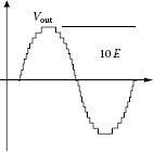
FIGURE 11.8
A 21-level waveform.
Similarly, higher-level inverters can be constructed by using higher-stage super-lift converters.
11.3 Simulation and Experimental Results
A 15-level super-lift inverter in a solar panel energy system is an example for simulation. The output voltage of a 15-level SL inverter is shown in Figure 11.9. The corresponding experimental result is shown in Figure 11.10.
For a 25-level super lift inverter in the solar panel energy system, the simulation and corresponding experimental results are shown in Figures 11.11 and 11.12, respectively.
Furthermore, we use the super-lift conversion technique to produce 35-level and 45-level super lift inverters for the solar panel energy system. Their output voltages have 35 and 45 levels, respectively. The simulation and experimental results are shown in Figures 11.13,11.14,11.15,11.16.
We introduced super-lift multilevel inverters in this chapter, which is a new approach to DC/AC inversion technology in the field. All super-lift multilevel inverters have a simple structure, straightforward operation procedure, easy control, and high output voltage. Fewer components are used to construct higher-level output voltage, and therefore the cost is lower. We have applied four SLIs from 15-level to 45-level of output voltage to a solar panel energy system and obtained satisfactory simulation and experimental results. These super-lift multilevel inverters can also be used in other renewable energy systems and industrial applications.
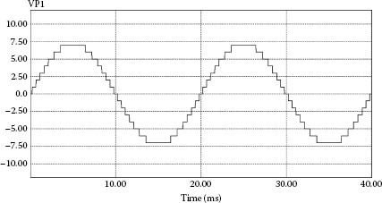
FIGURE 11.9
The simulation result of a fifteen-level SLI.
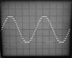
FIGURE 11.10
The experimental result of a fifteen-level SLI.
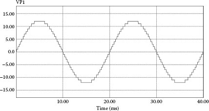
FIGURE 11.11
The simulation result of a 25-level SLI.

FIGURE 11.12
The experimental result of a 25-level SLI.
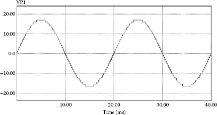
FIGURE 11.13
The simulation result of a thirty-five level SLI.
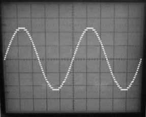
FIGURE 11.14
The experimental result of a 35-level SLI.
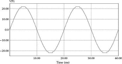
FIGURE 11.15
The simulation result of a 45-level SLI.
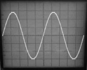
FIGURE 11.16
The experimental result of a 45-level SLI.
1. Luo F. L. and Ye H., 2004. Advanced DC/DC Converters. Boca Raton, FL: CRC Press.
2. Luo F. L. and Ye H. 2010. Power Electronics: Advanced Conversion Technologies. Boca Raton, FL: Taylor & Francis.
3. Luo F. L. and Ye H. 2002. Super-lift Luo converter. Proc. IEEE Int. Conf. PESC’2002, Cairns, Australia, 23–27 June, pp. 425–430.
4. Luo F. L. and Ye H. 2003. Positive output super-lift converters. IEEE Trans. Power Electron., Vol. 18, No. 1, January, pp. 105–113.