Switched Inductor Multilevel DC/AC Inverters Used in Solar Panel Energy Systems
Switched inductor multilevel DC/AC inverters will be described in this chapter. For convenience, we call them switched inductor inverters or SI inverters (SIIs).
Although switched capacitor inverters can reach high power density, their circuits are relatively complex with many switches and control circuitries [1–3]. If the difference between input and output voltages is large, multiple switched capacitor stages must be employed. Switched inductor inverters successfully overcame this disadvantage. Usually, only one inductor is required for each inverter no matter how large the difference between the input and output voltages. Therefore, the switched inductor inverter has very simple circuit and, consequently, very high power density.
A switched inductor inverter is shown in Figure 13.1a. It contains one inverter L, main switch S, and one Diode D. Figures 13.1b and 13.1c show the equivalent circuit when switch S is on and off, respectively.
13.2 Switched Inductor Used in Multilevel DC/AC Inverters
In this section, we show how to apply the switched inductor technique in multilevel DC/AC inverters.
A five-level switched inductor inverter is shown in Figure 13.2.
There is one DC voltage source E, one three-position band switch, and one change-over switch (2P2T) in the circuit. The main switch S is on or off with the duty cycle k = 0.5 to charge the two capacitors C1 and C2 with voltage E for each. Therefore, the operation status is as follows:
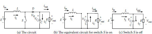
FIGURE 13.1
A switched inductor inverter.
• Vout = 2E: 2P2T is on, and the band switch is at position 2.
• Vout = E: 2P2T is on, and the band switch is at position 1.
• Vout = 0: The band switch is at position 0 (i.e., N).
• Vout = −E: 2P2T is off, and the band switch is at position 1.
• Vout = −2E: 2P2T is off, and the band switch is at position 2.
We have obtained a five-level output AC voltage. The output voltage peak value is two times the input DC voltage E. The waveform is shown in Figure 13.3.
A nine-level switched-capacitor inverter is shown in Figure 13.4.
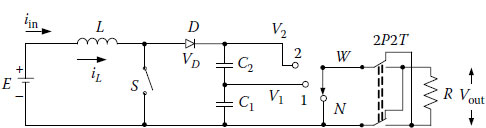
FIGURE 13.2
A five-level switched-inductor inverter.
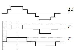
FIGURE 13.3
A five-level waveform.
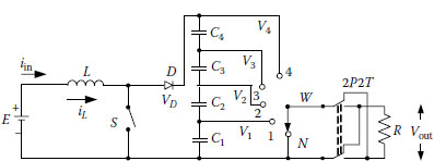
FIGURE 13.4
A nine-level switched-inductor inverter.
There is one DC voltage source E, one five-position band switch, and one change-over switch (2P2T) in the circuit. The main switch S is on/off with the duty cycle k = 0.2 to charge the four capacitors C1, C2, C3, and C4 with voltage E for each. Therefore, the operation status is as follows:
• Vout = 4E: 2P2T is on, and the band switch is at position 4.
• Vout = 3E: 2P2T is on, and the band switch is at position 3.
• Vout = 2E: 2P2T is on, and the band switch is at position 2.
• Vout = E: 2P2T is on, and the band switch is at position 1.
• Vout = 0: The band switch is at position 0 (i.e., N).
• Vout = −E: 2P2T is off, and the band switch is at position 1.
• Vout = −2E: 2P2T is off, and the band switch is at position 2.
• Vout = −3E: 2P2T is off, and the band switch is at position 3.
• Vout = −4E: 2P2T is off, and the band switch is at position 4.
We have obtained a nine-level output AC voltage. The output voltage peak value is four times the input DC voltage E. The waveform is shown in Figure 13.5.
13.2.3 Fifteen-Level SC Inverter
A 15-level switched-capacitor inverter is shown in Figure 13.6.
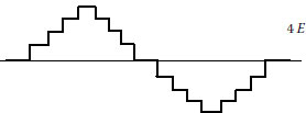
FIGURE 13.5
A nine-level waveform.
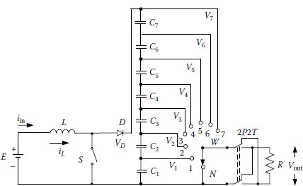
FIGURE 13.6
A fifteen-level switched-inductor inverter.
There is one DC voltage source E, one seven-position band switch, and one change-over switch (2P2T) in the circuit. The main switch S is on/off with the duty cycle k = 6/7 to charge the seven capacitors with voltage E for each. Therefore, all capacitors are charged to the voltage E in the steady state. The voltage at point 2 is V2 = 2 × E; at point 3 V3 = 3 × E; at point 4 V4 = 4 × E, and so on; (V1 is E). Therefore, the operation status is as follows:
• Vout = 7E: 2P2T is on, and the band switch is at position 7.
• Vout = 6E: 2P2T is on, and the band switch is at position 6.
• Vout = 5E: 2P2T is on, and the band switch is at position 5.
• Vout = 4E: 2P2T is on, and the band switch is at position 4.
• Vout = 3E: 2P2T is on, and the band switch is at position 3.
• Vout = 2E: 2P2T is on, and the band switch is at position 2.
• Vout = E: 2P2T is on, and the band switch is at position 1.
• Vout = 0: The band-switch is at position 0 (i.e., N).
• Vout = −E: 2P2T is off, and the band switch is at position 1.
• Vout = −2E: 2P2T is off, and the band switch is at position 2.
• Vout = −3E: 2P2T is off, and the band switch is at position 3.
• Vout = −4E: 2P2T is off, and the band switch is at position 4.
• Vout = −5E: 2P2T is off, and the band switch is at position 5.
• Vout = −6E: 2P2T is off, and the band switch is at position 6.
• Vout = −7E: 2P2T is off, and the band switch is at position 7.
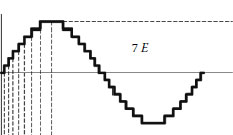
FIGURE 13.7
A fifteen-level waveform.
We have obtained a fifteen-level output AC voltage. The output voltage peak value is seven times the input DC voltage E. The waveform is shown in Figure 13.7.
Repeatedly adding the components in Figure 13.6, we can obtain higher-level inverters.
13.3 Simulation and Experimental Results
Switched inductor multilevel inverters in a solar panel energy system are examples for the simulation. The nine-level SI inverter has an output voltage with nine levels. The simulation result is shown in Figure 13.8. Its corresponding experimental result is shown in Figure 13.9. The 19-level SI inverter has an output voltage with 19 levels. The simulation result is shown in Figure 13.10. The corresponding experimental result is shown in Figure 13.11
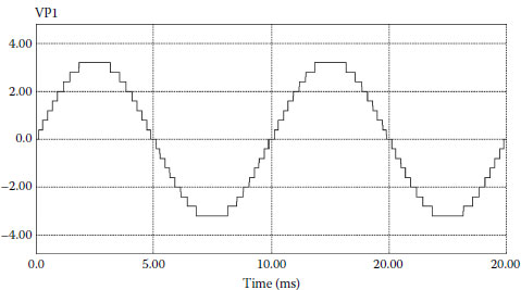
FIGURE 13.8
A nine-level simulation waveform.
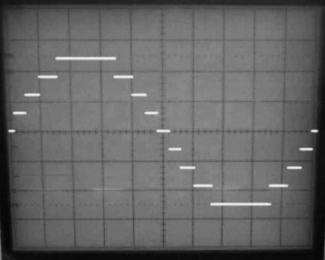
FIGURE 13.9
A nine-level experimental waveform.
Furthermore, we use the switched-inductor technique to produce 39-level and 49-level SI inverters for the solar panel energy system. Their output voltages have 39 levels and 49 levels, respectively. Their simulation and corresponding experimental results are shown in Figures 13.12, 13, 14 and 13.15.
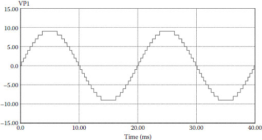
FIGURE 13.10
A 19-level simulation waveform.
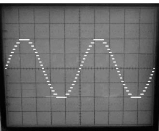
FIGURE 13.11
A 19-level experimental waveform.
We have introduced switched inductor multilevel inverters in this chapter. All SL multilevel inverters have advantages such as very simple structure, straightforward operation procedure, easy control, and higher output voltage (compared with the input voltage). Fewer components are needed to construct higher levels of output voltage. We applied four SIIs from 9-level to 49-level of output voltage to a solar panel energy system and obtained the satisfactory simulation and experimental results, which strongly supported our circuit design. These SI multilevel inverters can be used in other renewable energy systems and industrial applications.
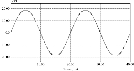
FIGURE 13.12
A 39-level simulation waveform.
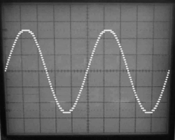
FIGURE 13.13
A 39-level experimental waveform.
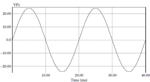
FIGURE 13.14
A 49-level simulation waveform.
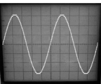
FIGURE 13.15
A 49-level experimental waveform.
1. Luo F. L. and Ye H. 2010. Power Electronics: Advanced Conversion Technologies. Boca Raton, FL: Taylor & Francis.
2. Luo F. L. and Ye H. 2004. Advanced DC/DC Converters. Boca Raton, FL: CRC Press.
3. Luo F. L. and Ye H. 2000. Multi-quadrant switched inductor luo-converter. Int. J. Power Supply Technol. Applicat. Vol. 3, No. 6, pp. 258–263.