Peregrine at the National Renewable Energy Laboratory
National Renewable Energy Laboratory
7.1.1 Design Features, Efficiency and Sustainability Measures
7.1.2 Sponsor/Program Background
7.2 Applications and Workloads
7.2.1 Computational Tasks and Domain Examples
7.7 Visualization and Analysis
7.8.1 NREL Energy Efficient Data Center
7.8.2 ESIF Data Center Mechanical Infrastructure
7.8.3 ESIF Data Center Electrical Power
While the focus here is typically on computer systems, the origins of this system, named Peregrine, are tightly linked to the facility and a holistic approach to energy efficient high performance computing in which the system is intimately tied to the data center and the data center is integrated in the larger research facility. The U.S. Department of Energy’s National Renewable Energy Laboratory (NREL), located in Golden, Colorado, is world renowned for its commitment to green building construction and for leading by example. NREL recently completed the Energy Systems Integration Facility (ESIF), a new 182,000-square-foot research facility that includes high bay and laboratory space, office space for about 220 staff, and an ultra-efficient, showcase high performance computing (HPC) data center. This showcase facility was built in accordance with the U.S. Green Buildings Council’s standards and has achieved a Leadership in Energy and Environmental Design (LEED)1 Platinum Certification. In February 2014, the Energy Systems Integration Facility was awarded the 2014 Lab of the Year Award in R&D Magazines 2014 Laboratory of the Year Competition.
Peregrine is composed of 1440 computational nodes based on Intel Xeon processors and Intel Xeon Phi coprocessors, with a peak speed of 1.2 Petaflops, making it the world’s fastest HPC system dedicated to advancing renewable energy and energy efficiency technologies. The data center itself features a chiller-less design, direct warm-water liquid cooling, and waste heat capture/re-use, and it operates at an annualized average PUE rating of 1.06 or better, making it the world’s most energy-efficient data center. This data center demonstrates technologies that save energy and water, reduce CO2 emissions, and capture/re-use waste heat with an estimated annualized average Energy Reuse Effectiveness of 0.7. Planning for the new research facility and innovative data center focused on a holistic “chips to bricks” approach to energy efficiency to ensure that the HPC system and data center would have a symbiotic relationship with the ESIF offices and laboratories, and to integrate the new facility into NREL’s campus.
7.1.1 Design Features, Efficiency and Sustainability Measures
Several key design specifications have led to the data center’s extreme efficiency. First, high-voltage electricity (480VAC rather than the typical 208VAC) is supplied directly to the racks, which saves on power electronics equipment (cost savings), power conversions, and electrical losses (energy savings).
Secondly, the data center uses warm-water liquid cooling supplied directly to the server racks. The decision to use liquid cooling was made several years ago, before liquid-cooled systems were routinely available. There are several advantages to this approach. Water as a heat-exchange medium is three orders of magnitude more efficient than air, and getting the heat exchange close to where the heat is generated is most efficient. Also, 75°F water supplied for cooling the computers allows the data center to use highly energy-efficient evaporative cooling towers, eliminating the need for much more expensive and more energy-demanding mechanical chillers, saving both capital and operating expenses. Using the new 2014 ASHRAE liquid cooling supply water temperature classification, the NREL data center is a class W2 facility, meaning that the cooling supply is warmer than 17°C but cooler than 27°C. Additionally, the hydronic system features “smooth piping,” where a series of 45°angles replace 90°angles wherever possible to reduce pressure drops and further save pump energy. The evaporative cooling towers are paired with remote basins to eliminate the use of basin heaters, while pumps and heat exchangers efficiently transfer heat to where it is needed. Thus, the data center’s high energy efficiency is achieved with best-in-class engineering practices and widely available technologies.
The ESIF data center is designed and built to capture the “waste” heat generated by the HPC system for heating within the building. By design, the hot water returned from the HPC system must be 95°F or warmer, and at least 90% of the heat load from the HPC system must be dissipated directly to the hydronic system. By focusing on direct liquid cooling, the energy needed to cool the computer systems decreases dramatically, as does fan energy use. The data center is heavily instrumented to continually monitor data center efficiency and to provide real-time optimization of energy usage.
By capturing the computer waste heat directly to liquid and integrating the data center into the ESIF, the data center serves as the primary heat source for office and laboratory space within the facility. Data center waste heat is also used to heat glycol loops located under an adjacent plaza and walkway, melting snow and making winter walks between buildings safer for laboratory staff. As the HPC system expands to meet demand, data center heat output will exceed the heating needs of the ESIF. Mechanical systems and infrastructure are planned to allow for future export of this heat to other facilities on NREL’s campus. In addition to winter heating, the long-term goal is for the data center to become the summer campus water heating system, allowing central heating boilers to be shut down.
NREL’s new data center features the first petascale HPC system to use warm-water liquid cooling and will be the first to reach an average PUE rating of 1.06 or better. In the long term, the computer industry trend is toward more cores per chip and continued increases in power density, making efficient cooling of large data centers increasingly difficult with air alone. While the particulars for efficient cooling of servers and heat rejection will vary depending on site-specific conditions, the fundamentals and approaches used here are widely applicable and represent a new best-in-class standard. NREL’s leadership in warm-water liquid-cooled data centers coupled with waste heat re-use will pave the way for the federal government and the private sector to continue to meet increased demand for data, services, and computational capability at a much higher efficiency than has been achieved to date, reducing energy demand and saving money.
7.1.2 Sponsor/Program Background
Stewardship for Peregrine is provided by the U.S. Department of Energy’s Office of Energy Efficiency and Renewable Energy (EERE), which accelerates development and facilitates deployment of energy efficiency and renewable energy technologies and market-based solutions that strengthen U.S. energy security, environmental quality, and economic vitality.
EERE is at the center of creating the clean energy economy today. It leads the U.S. Department of Energy’s efforts to develop and deliver market-driven solutions for energy-saving homes, buildings, and manufacturing; sustainable transportation; and renewable electricity generation. The focus of the modeling and simulation on Peregrine is to support and advance these efforts.
The timeline for this project involved an integrated construction project to build the new research facility as well as a project for the specification and acquisition of the new high performance computing system itself. The two projects were coordinated so that the new system would be delivered shortly after the data center in the new facility was commissioned. This coordinated project schedule is highlighted in Table 7.1 and major elements are described below.
Construction of the ESIF facility was undertaken using a Design-Build approach in which the design and construction services were contracted by a single entity known as the design-builder or design-build contractor. In contrast to design-bid-build, design-build relies on a single point of responsibility contract and is used to minimize risks for the project owner and to reduce the delivery schedule by overlapping the design phase and construction phase of a project.
The Peregrine implementation project team worked closely with the design-build team to implement the “last mile” piping and electrical distribution panels while the construction team was still on-site finishing the laboratory portion of the ESIF facility. The datacenter portion of the facility was commissioned and ready for computing hardware in October 2012.
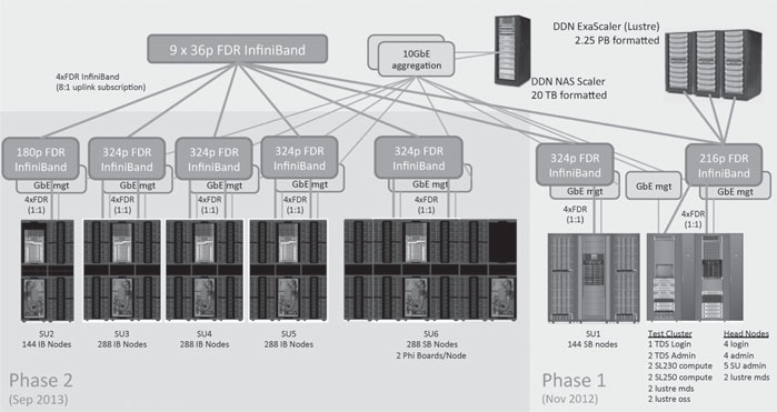
Peregrine Phase 1a equipment was delivered in November 2012. It consisted of Peregrine’s test cluster, ethernet and InfiniBand core infrastructure, NFS and Lustre filesystems, and 144 compute nodes. See Figure 7.2 for system architecture overview. The Phase 1a system enabled HP and NREL to finalize the OS stack and build the required scientific applications.
The Phase1b equipment delivered mid-February 2012 marked the first shipment of water-cooled equipment. Peregrine’s cooling system interfaces with the ESIF Energy Recover Water (ERW) loops via heat exchange and pump modules called Cooling Distribution Units (CDUs). CDUs receive water up to 75°F from the ERW Supply pipes and return that water and 95°F (or warmer) to the ERW Return side. The CDU interface with the ESIF ERW piping is called the primary side.
TABLE 7.1: Key facility and system dates for Peregrine.
ESIF Milestone |
Date |
Peregrine Milestone |
Construction Started |
Apr 2011 |
HPC system requirements collected |
Feb 2012 |
RFP released to Vendors |
|
Mar 2012 |
RFP responses due from Vendors |
|
Jul 2012 |
Contract awarded to Hewlett Packard |
|
Peregrine Primary Cooling Piping Complete |
Aug 2012 |
Detailed site preparation |
HPC Datacenter Commissioned |
Oct 2012 |
|
Offices and Datacenter Complete |
Nov 2012 |
Phase 1a delivery (air cooled nodes, infrastructure, storage) |
Electrical Panels Complete |
Dec 2012 |
|
Phase 1b Secondary cooling loop hot work |
Feb 2013 |
Phase 1b delivery (prototype water-cooled nodes and CDUs) |
Phase 2 Secondary manifold installation |
Aug 2013 |
Phase 2 Initial Delivery (first water-cooled Ivy Bridge nodes) |
Sep 2013 |
Phase 2 final Delivery (water-cooled Ivy Bridge and Phi nodes) Secretary Moniz dedicates Peregrine |
|
Oct 2013 |
Physical Installation Complete |
|
Nov 2013 |
System acceptance passed |
|
Jan 2014 |
Full production use commences |
The CDUs distribute water to the compute racks via a distribution manifold built of 2.5 inch copper pipes located below the floor. The CDU interface with the compute racks is called the secondary side. The prototype CDU design located the primary and secondary supply and return pipes at the bottom of the rack, near the middle of the rack.
For this first of a kind system, installing the first engineering prototype CDUs required custom copper piping to be installed on-site from beneath the raised floor. The plumbing crew cut, fitted and sweated each connection to build up the cooling infrastructure. This first installation process took about three weeks and required frequent “hot” work in the datacenter as most joints needed to be soldered in place.
Phase 1b water-cooled equipment consisted of four prototype node racks and two prototype CDU racks. The compute node racks were about 8 feet tall, just tall enough to be of concern fitting onto the freight elevator and through the datacenter door. The compute racks were shipped in two pieces, designed to be stacked once on-site. Once the node racks were stacked, final plumbing network, and power connections were made and tested. Phase 1b also included a full scalable unit (288 nodes) of HP SL230 air-cooled nodes.
It is worth noting that the four engineering prototype liquid cooled racks and two CDUs were delivered to NREL on February 19, 2013. Just eight days later, the integrated system achieved 204.1 TeraFlops of HPL performance on February 27, 2013. This was just one week after prototype rack delivery to NREL.
Phase 2 delivery occurred in August and September 2013. Scalable units were shipped from HP’s engineering facility in Houston, TX as they passed component and integrated testing at HP.
The biggest changes from the first engineering prototypes racks to the first product shipment were with the cooling infrastructure. HP moved the CDU inlet and outlet water connections to the back of the racks, allowing connections to be made from above the floor. Water connections were made with flexible rubber hoses with quick connect fittings rather than requiring custom-fitted copper piping. The secondary loop cooling distribution manifold, which had required weeks of custom hot work was now composed of prefabricated modular manifolds. Installation time for secondary manifolds shrank from three weeks to support six racks of equipment to three days for 17 racks of equipment, greatly accelerating site prep and installation time.
7.2 Applications and Workloads
7.2.1 Computational Tasks and Domain Examples
Peregrine is the flagship computing resource of DOE’s Office of Energy Efficiency and Renewable Energy. It supports a wide variety of domain science, engineering, and analysis communities, including solar energy, bioenergy, wind and water, fuel cells, and advanced manufacturing as well as energy efficient vehicles and buildings. Some of these are model-centric, with modest computing requirements; some are simulation-centric, with either needs for traditional HPC resources in highly coupled calculations, or high capacity resources for many uncoupled calculations used for design and optimization work. Some are data-centric, requiring massive storage with high I/O bandwidth and low-latency access. Overall, the project portfolio supported on Peregrine leads to a diversity of user needs, and the system needs to provide value across the entire user community. Historically, most of the compute cycles have been utilized in applications related to materials physics and chemistry, wind energy and bioenergy applications.
1. Materials Physics and Chemistry. The discovery of new materials with better properties than the current standards is a continual challenge, and computational physics and chemistry is a foundation stone supporting the process of materials design, synthesis, testing, scaling, and ultimate commercialization. Solar photovoltaics, fuel transformation catalysis, and reactivity in advanced fuel cell and battery architectures are several examples where computation is making an impact. Particular challenges for high-performance computing are large crystalline unit cells needed to describe low-density defects and doping as well as complex surfaces, pseudocrystalline and amorphous materials that require large numbers of atoms in simulations of dynamical processes, and characterization of chemical spaces, where explicit enumeration is required absent known relationships of continuity and smoothness between structures and properties.
2. Wind Resource Modeling. The advanced state of wind commercial penetration relative to earlier technologies makes understanding the available wind resource critical. To this end, researchers are attempting to model more complex environments over larger geographic regions, and simulate them with higher fidelity, larger couplings between model elements, for longer times. This effort creates a significant demand for performance and application scalability with respect to nodes, cores, memory, and I/O. In addition, downstream processing requires large dataset handling and extreme visualization techniques.
3. Bioenergy. Lignocellulose, a catch-all term for most plant matter not suitable for direct use as food, is a potentially important feedstock for production of fuels and chemicals at scale. Within the context of biotechnology, the focus is on transforming this diverse and heterogeneous material into sugar, which serves as a more or less universal precursor for metabolic transformations to alcohols (e.g., ethanol) or post-ethanol “advanced biofuels,” as well as fine chemicals or drug precursors outside of the energy world. A primary concern for lignocellulosic feedstocks is their recalcitrance to most chemical and biochemical processes for sugar production. Much research is therefore geared to understanding the production of lignocellulose (in order to engineer less recalcitrance), the physics and chemistry of lignocellulose itself (both to understand the detailed mechanisms of recalcitrance, and to better hypothesize molecules that can transform chemical motifs within it), and the action of enzymatic catalysts on lignocellulose (to derive principles from which to engineer these enzymes via mutagenesis). Much of the application demand in this field on Peregrine is molecular dynamics, whereby a classical atomistic or coarse-grained model of the lignocellulose or LC-enzyme system is propagated in time subject to approximate Hamiltonians describing the energy and forces within the system.
Although a wide variety of applications are supported and run on Peregrine, several constitute major shares of the overall available allocation time. Unlike traditional HPC systems or today’s leadership-class facilities, the dominant workload around these heavily used applications is not predicated on large coupled calculations with latency and bandwidth demands on the communication fabric. Rather, high-throughput calculations with substantial demands on I/O, disk capacity, and scheduling resources predominate. This usage pattern is to be expected given the greater emphasis on discovery (where spaces need to be enumerated and searched) and predictive reliability (UQ) characteristic of NREL’s mission space in the world of near-commercial science and technology. Nevertheless, while these codes are usually run without an explicit requirement for traditional HPC scalability, they often carry the capacity for larger-scale runs, and/or sufficient architectural or algorithmic complexity associated with parallelism to be of interest to the computer science community.
1. The Weather Research and Forecasting Model (WRF) [3] is a mesoscale numerical weather prediction system designed to serve both atmospheric research and operational forecasting needs (see www.wrf-model.org). At NREL it is used for high resolution research forecasting to study the potential for solar and wind power generation. It has been run for both large (continental U.S.) and smaller, more limited geographical areas. WRF is one of the applications that is run on Peregrine using a large number of nodes per job. A set of simulations may be run to simulate a year or more of weather conditions, leading to a large volume of grid-based output data that must be saved for subsequent analysis.
2. The Vienna Ab Initio Simulation Program (VASP), developed by the Computational Materials Physics group at the Universit¨at Wien [2] is a standard in the materials physics and chemistry communities. The package’s multiple capabilities are centered around electronic structure and ab initio molecular dynamics, using plane-wave expansions of the wave-function to solve approximately the non-relativistic time-independent Schrödinger equation. Density functional and Hartree-Fock methods are fundamental to more advanced quasiparticle and many-body perturbation theories. The analytical capabilities of the software tuned to materials science drive much of its demand, and it is a workhorse program for calculating band structures, surface reaction intermediate and transition state energies, and excited-state properties for bulk materials, in which a crystalline unit cell is periodic in three dimensions, or surfaces, where a layer of vacuum separates atomically dense images along one dimension (i.e., the material is periodic in two dimensions, with the third representing a vacuum-bounded cleavage plane).
3. Gaussian [1] is perhaps the best known package for molecular quantum chemistry. The first commercial release of this package dates back to 1970, and the legacy of hardware against which the package was optimized as well as the working models that have grown up around it may have something to do with the software’s strengths today. The current major release, Gaussian09, is capable of distributed memory paralellism via the Linda programming model. Operationally, this amounts to internode communications via shell sessions on each working node. However, the software’s dominant strengths lay in a huge assembly of quantum chemical methodological implementations, large shared-memory calculations, and algorithmic adaptation to optimize the use of these resources. Shared-memory parallelism is realized via standard OpenMP threading.
Peregrine is a Hewlett-Packard (HP) 1.2 petaflop/s cluster based on Intel Xeon E5-2670 SandyBridge processors, Intel Xeon E5-2695v2 IvyBridge processors, and Intel Xeon Phi 5120D coprocessors. Peregrine is comprised of 6 scalable units (SUs) containing a total of 1440 dual-socket computational nodes. Four types of dual-socket compute nodes are provided: (1) 16-core SandyBridge nodes, (2) 24-core IvyBridge nodes, (3) 24-core IvyBridge nodes with 64 GB of memory, and (4) 16-core SandyBridge nodes equipped with Intel Xeon Phi coprocessors. Peregrine is equipped with an InfiniBand FDR interconnect. Full bisection bandwidth is available within each SU of 144 or 288 nodes. SUs are connected to each other with an 8:1 over-subscription.
Peregrine’s storage sub-system includes 2.25 petabytes of Lustre storage for scratch and shared project storage, and 40 terabytes of NFS storage for home and cluster software.
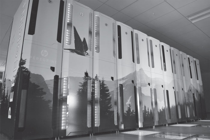
Figure 7.1 shows seven water-cooled s8500 enclosures (with blue lights visible) and 4 Cooling Distribution Units in the ESIF HPC data center. The skin applied after installation depicts Colorado landscape and Peregrine falcon.
Figure 7.2 provides a high-level overview of the Peregrine System. The Phase 1 system includes the core InfiniBand and Ethernet network infrastructure, Network Attached Storage (NAS) subsystem, Parallel File System (PFS), system infrastructure servers (login, administration and Lustre MDS nodes), one scalable unit (SU) of SandyBridge nodes, and a test cluster. The Phase 2 system depicted with a green background includes SUs of IvyBridge nodes and 1 scalable unit of SandyBridge nodes equipped with Intel Xeon Phi coprocessors.
FIGURE 7.1: Picture of Peregrine.
FIGURE 7.2: Peregrine architectural system overview.
SU1 consists of two racks, where each rack is composed of 72 SL230G8 compute nodes. Each node is a 1U, half-width form factor with dual 8-core Xeon E5-2670 SandyBridge processors running at 2.6 Ghz and equipped with 32 GB of 1600 Mhz DDR3 memory and Mellanox Connect X-3 FDR Infini-Band HCA and two Intel Xeon Phi coprocessors.
TABLE 7.2: Peregrine hardware configuration.
Feature |
SU1 |
SU[2-4] |
SU5 |
SU6 |
Node Architecture |
HP Proliant |
HP Proliant |
HP Proliant |
HP Proliant |
SL230 |
SE2x8530a |
SE2x8530a |
SE8550a |
|
CPU |
Intel Xeon |
Intel Xeon |
Intel Xeon |
Intel Xeon |
E5-2670 |
E5-2695v2 |
E5-2695v2 |
E5-2670 |
|
CPU microarchitecture |
SandyBridge |
IvyBridge |
IvyBridge |
SandyBridge |
CPU Frequency (GHz) |
2.6 |
2.4 |
2.4 |
2.6 |
CPU Count per Node |
2 |
2 |
2 |
2 |
Xeon Cores per Node |
16 |
24 |
24 |
16 |
Node Memory Capacity (GB) |
32 |
32 |
64 |
32 |
Phi Accelerator |
Intel Xeon |
|||
Phi 5120D |
||||
Phi Count per Node |
2 |
|||
Phi Memory Capacity (GB) |
8 |
|||
Interconnection Network Network Ports per Node |
InfiniBand 4x FDR 1 Mellanox Connect X-3 IB FDR HCA |
|||
Compute Racks |
2 |
5 |
2 |
4 |
Total number of nodes |
144 |
720 |
288 |
288 |
Peak FLOP Rate (TF) |
47.92 |
331.78 |
132.71 |
678.11 |
SU[2-5] are housed in seven rack enclosures of dual socket Intel IvyBridge based compute nodes. Each HP S8500 liquid cooled heat capture and re-use enclosure includes 144 SE2x8530a compute nodes. Each node is a 1U, half-length form factor with dual 12-core Xeon E5-2695v2 “IvyBridge” processors running at 2.4 Ghz and equipped with 32 GB (SU[2-4]) or 64 GB (SU5) 1600 Mhz DDR3 memory and Mellanox Connect X-3 FDR InfiniBand HCA.
SU6 includes four rack enclosures of dual socket Intel SandyBridge based compute nodes equipped with Intel Xeon Phi coprocessors. Each HP s8500 enclosure includes 72 SE8550a compute nodes and 144 Intel Xeon Phi 5120D coprocessors. Each node is a 1U, half-length form factor with dual 8-core Xeon E5-2670 “SandyBridge” processors running at 2.6 Ghz and equipped with 32 GB of 1600 Mhz DDR3 memory and Mellanox Connect X-3 FDR InfiniBand HCA and two Intel Xeon Phi coprocessors.
Peregrine’s interconnect is based on 4x Fourteen Data Rate (FDR) Mellanox SX6518 324-Port InfiniBand Director Switches and Mellanox SX6025 36-port 56 Gb/s InfiniBand Switch Systems. Each scalable unit is equipped with a 324-port switch. This configuration provides full bisection bandwidth within each scalable unit supporting job sizes up to 6912 cores. Nine 36-port switches provide “top” connectivity. Scalable units are connected to each other at an oversubscription ratio of 8:1, which provides sufficient bandwidth so that any scalable unit can fully utilize the central Lustre filesystems.
Peregrine has two data storage subsystems. The Network Attached Storage (NAS) solution offers NFS to all peregrine nodes. NAS storage is provided by DDN based on 10K SFAs and a pair of cluster “heads” which run a software stack that offers the block storage as NFS volumes. Peregrine has two filesystems shared from the NFS solution. /home is a 10 TB filesystem which provides user home directories. /nopt is a 2 TB filesystem which is NREL’s shared /opt filesystem, which contains the shared software, compilers, modules and other cluster-wide software.
The Parallel File System (PFS) cluster is a Lustre-based solution offering lustre to Peregrine compute and login nodes. The PFS solution is provided by DDN based on 12K SFAs which contain virtual Object Storage Servers that share lustre Object Storage Targets to Peregrine. PFS provides two filesystems: /scratch is a system-wide scratch filesystem, and /projects is a shared collaboration space where projects can store common data.
The HP s8500 liquid cooled enclosure implements a hybrid cooling approach, providing component-level liquid cooling to CPUs, Accelerators and DIMMs, and using a liquid to air heat-exchanger for the remaining parts. Peregrine includes eleven s8500 enclosures.
The s8500 has four 480/277 AC 30A 5-pin connectors, capable of providing 20 kW each for a total of 80 kW per rack. The 480AC power feed to the s8500 allows for enhanced power delivery efficiency gains, saving the 3-5% loss in the commonly deployed 480AC to 208AC transformer.
Power supplying each rack is coordinated via a lighting contactor that energizes or de-energizes all four circuits at one time. The s8500 enclosures are configured to send a 24-volt signal to coorsponding lighting contactors which remotely de-energize all 480 volt power to racks if a leak has been detected.
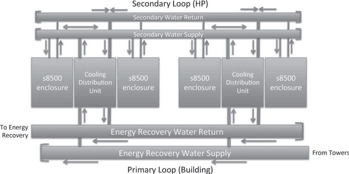
The Hydronics subsystem provides warm-water cooling waters to the s8500 enclosures. Figure 7.3 depicts the configuration of the hydronics system on Peregrine. Peregrine’s Cooling Distribution Units (CDUs) are deployed in pairs in an N+1 configuration so that two CDUs provide water to four s8500 enclosures.
Water is provided to CDUs by the ESIF facility energy recovery water loop. Water returning from ESIF’s main mechanical room has been cooled by water towers to a maximum of 75°F. CDUs manage primary water flow through their heat exchangers, flowing the right amount of water to ensure adequate cooling while returning water at least 95°F to the energy recovery water loop. Energy recovery water is routed to a heat exchanger that transfers heat to the building heating system before returning to the ESIF main mechanical room.
The CDUs pump water through a secondary water manifold system that distributes water to the s8500 enclosures. CDUs coordinate with each other to ensure adequate cooling is provided at all times.
FIGURE 7.3: Peregrine hydronics sketch.
The Operating System stack on Peregrine is typical for Linux clusters. Table 7.3 summarizes the major software packages installed on Peregrine.
TABLE 7.3: Peregrine software configuration.
Feature |
Software |
Version |
Login and Admin Node OS |
RHEL |
6.2 |
Compute Node OS |
CentOS |
6.2 |
Parallel Filesystem |
Lustre |
2.1 |
Cluster Management |
HP Configuration Management Utility (CMU) |
7.1 |
Compilers |
Intel |
12 |
PGI |
12 |
|
GNU |
4.1 |
|
MPI |
IntelMPI (default) |
4.1 |
OpenMPI |
1.7 |
|
Notable Libraries |
HDF5 |
1.8 |
netcdf/pNetCDF |
4.1/1.3 |
|
Intel MKL |
13 |
|
Software Environment Management |
Modules |
3.2.10 |
Job Scheduler |
Moab |
7.2 |
Resource Manager |
Torque |
4.2 |
Debugging Tools |
TotalView |
8.11 |
Operating systems are deployed via the HP Configuration Management Utility (CMU). CMU manages provisioning of diskless node images and deployment. Node images are created on a golden master node. CMU adapts images for deployment to Peregrine’s diskless nodes. At present, two node configurations are maintained. One configuration is deployed to nodes equipped with the Intel Xeon Phi coprocessors. The other configuration is deployed to all the other nodes.
Shared software is deployed to the /nopt filesystem residing on Peregrine’s NAS storage. Software is made available to users via the module’s software environment management system.
One acute need identified early was the ability to install additional RedHat Package Manager (RPM) packages on a regular basis. Deploying RPMs to nodes in the normal fashion would require installation on a golden node, then reboot of nodes into the new image. This approach was not flexible nor fast enough to serve user needs on Peregrine, so an alternative mechanism was developed.
The approach involves installing desired packages onto a standalone server using yum. Considerable time is saved by using RPM software installation methods instead of manually acquiring each package, tracing dependencies, building, installing and testing packages.
Once the desired software environment is installed on the standalone server, a complete copy is replicated onto the /nopt filesystem. A module is provided adding library and binary paths to a user’s environment. Since many of the desired packages appear in the Extra Packages for Enterprise Linux (EPEL) RPM repository, this module was named “epel.”
Peregrine is built with Intel Xeon and Intel Xeon Phi coprocessors so the primary programming models are standards-based, including threads, OpenMP and MPI. The Xeon Phi coprocessors may also be used via Intel compiler-specific offload methods.
Because Peregrine runs standard Linux, a wide variety of languages and compilers are available, including C, C++, Fortran, Python and Java. Supported compiler suites include Intel, PGI and the GNU compilers. Intel MPI, mvapich2 and OpenMPI libraries are all available. The modules package is used to allow users to easily choose a compatible set of compilers and libraries.
The primary performance analysis tools on Peregrine are Intel VTune Amplifier XE 2013 and Intel Trace Analyzer and Intel Trace Collector. Other tools include Stat and TAU. Debuggers and correctness tools include the Rogue-Wave Totalview debugger and Intel Inspector XE 2013.
7.7 Visualization and Analysis
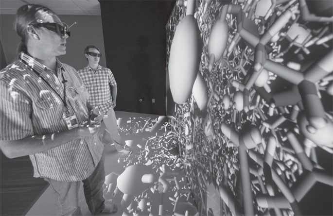
Peregrine supports advanced visualization and analysis both remotely and in-person. To support remote visualization and analysis, Peregrine is equipped with a large-memory data analysis and visualization (DAV) node with hardware-accelerated graphics card. The DAV node is a 4U form factor with four 8-core Xeon E5-4670 “SandyBridge” processors running at 2.6 GHz with 368 GB of 1600 MHz DDR3 memory and a Nvidia Quadro 6000 (see Table 7.4). The DAV node is used as an interactive system to support remote visualization applications as single jobs, which may contain one or more threads, potentially accessing all the memory contained within the node as a single address space. This is implemented by using TurboVNC to provide users the ability to run advanced visualization applications remotely on an interactive desktop. VirtualGL is used to provide access to the DAV graphics hardware by redirecting OpenGL rendering instructions to the DAV graphics card and copying the results to destination windows on the VNC desktop. To support in-person visualization, Peregrine is equipped with a visualization gateway node that exports the Peregrine file systems to NREL’s state-of-the-art visualization laboratory, the ESIF Insight Center, which includes an immersive virtual environment and large-scale display walls (see Figure 7.4). The visualization gateway node connects to the Peregrine network with FDR InfiniBand and provides two 10 G connections to the Insight Center display systems.
The Insight Center Visualization Room provides meeting space that features a large, rear-projected, 14 megapixel image display. Large-scale, high-resolution visual imagery can be used to effectively convey information and illustrate research findings to stakeholders and visitors. The Visualization room also boosts the exchange of ideas among NREL researchers and their collaborating partners. Using the high-resolution, large-scale display, researchers and others now have the visual “real estate” to lay out a significant amount of data that will enable them to analyze large-scale simulations, ensembles of simulations, and highly detailed visual analytics displays.
TABLE 7.4: Peregrine DAV hardware configuration.
Feature |
System |
|
Node Architecture |
HP Proliant DL560 Gen 8 |
|
CPU |
Intel Xeon E5-4670 |
|
CPU microarchitecture |
SandyBridge |
|
CPU Frequency (GHz) |
2.6 |
|
CPU Count per Node |
2 |
|
Xeon Cores per Node |
16 |
|
Node Memory Capacity (GB) |
368 |
|
Graphics Accelerator |
Nvidia Quadro 6000 |
|
Graphics Memory Capacity (GB) |
6 |
|
Interconnection Network |
InfiniBand 4x FDR |
FIGURE 7.4: Photograph of NREL scientists analyzing a Peregrine molecular dynamics simulation in the ESIF Insight Center.
The Collaboration Room provides multiple workspaces in which researchers and partners from all disciplines of science and engineering can interactively visualize highly complex, large-scale data, systems, and operations. In this area, researchers can view in real time the testing and simulation of equipment and technologies. The collaboration room is intended to support the analysis of a wide range of research within the EERE mission. Research areas include any that generate large-scale data. Simulation data (data that produce a representation of a spatial system or model and possibly its evolution in time), may span from the atomistic scale of a molecular dynamics simulation of new materials to the planetary boundary scales of turbine wakes and other turbulent structures in multi-turbine array simulations. Measured data (tested data as opposed to predicted or estimated data) spans from the nanostructures in 3D microscopy data of biomass pretreatments to the complex dynamics of the North American electrical power grid. The main workspace is a stereoscopic immersive virtual environment composed of six projectors that illuminate two surfaces – a wall and the floor. The projected space can be used in conjunction with an optical tracker and the visualizations respond in relation to the movement of the user. This allows users to physically explore and interact with their data as shown in Figure 7.4.
Peregrine resides at the National Renewable Energy Laboratory (NREL), a U.S. Department of Energy laboratory, located in Golden, Colorado, dedicated to research and advancing renewable energy and energy efficiency technologies. The system is housed in NREL’s new state-of-the-art, energy efficient data center described below.
7.8.1 NREL Energy Efficient Data Center
In the fall of 2012, NREL completed construction of the new Energy System Integration Facility (ESIF), providing laboratory and office space for approximately 200 NREL researchers staff. The focus of this new 182,500 ft2 facility is research to overcome challenges related to the interconnection of distributed energy systems and the integration of renewable energy technologies into the electricity grid. Following NREL’s tradition of “walking the talk,” the ESIF demonstrates NREL’s commitment to a sustainable energy future with its energy-saving workplace environment [2]. This showcase facility not only helps meet the nation’s crucial research objectives for integrating clean and sustainable energy technologies into the grid, but was built in accordance with the U.S. Green Buildings Council’s LEED Platinum Certification standards.
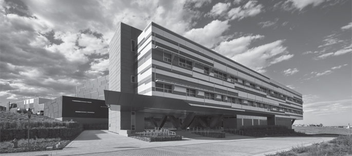
This new facility shown in Figure 7.5 includes a state-of-the-art data center, which is itself a showcase facility for demonstrating data center energy efficiency. The office space is shown in the front right, the energy efficient data center is the onyx black and chrome middle section of the building and research laboratory space is set back behind the data center. It is designed to achieve an annualized average power usage effectiveness (PUE) rating of 1.06 or better making it the world’s most energy efficient data center. The primary focus is on warm water, liquid-cooled of high power computer components. There are no mechanical or compressor-based cooling systems. The cooling liquid is supplied indirectly from cooling towers and thus the ambient temperature is warmer than typical data centers. Finally, waste heat from the HPC systems is captured and used as the primary heat source in the ESIF office, laboratory space, and to condition ventilation makeup air. The ESIF data center has approximately 10,000 ft2 of uninterrupted, usable machine room space. Subtracting present and planned systems, there is over 7,000 ft2 of computer-ready space.
FIGURE 7.5: The Energy System Integration Facility at NREL.
7.8.2 ESIF Data Center Mechanical Infrastructure
The NREL data center differs from most data centers in the way it handles waste heat. As mentioned above, the primary focus is on warm water, liquid cooling high power computer components. While both air-cooled and liquid cooled cooling solutions can be accommodated, the data center is provisioned to air-cool up to a maximum of 10% of the total heat load. Thus, at least 90% (and up to 100%) of the total heat generated is dissipated to liquid. For liquid cooled systems, both direct liquid or indirect liquid cooling approaches are acceptable.
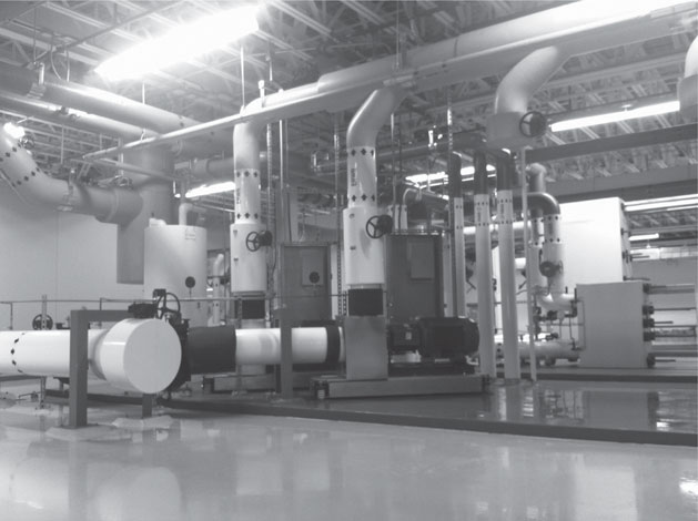
FIGURE 7.6: The NREL HPC data center mechanical space.
In addition to providing ultra efficient systems to reject un-needed waste heat (summer operation), it captures and re-uses the waste heat within the building to offset heating loads in office and lab space as well as condition ventilation air. As a result, there is a greater emphasis on maximizing the waste heat available and ensuring a high quality of waste heat. Some key features of the mechanical systems include: (1) Compressor-free cooling of data center equipment; (2) All pumps and fans utilize energy efficient, variable frequency drives; and (3) Central HVAC systems are designed for low velocity operation.
The energy recovery water system provides hydronic cooling for both the HPC data center and central HVAC equipment. Cooling water delivered to the computer equipment will vary between 60°F and 75°F. Using the new 2014 ASHRAE liquid cooling supply water temperature classification, the NREL data center is a class W2 facility, meaning that the cooling supply is warmer than 17°C but cooler than 27°C. This temperature variation is based primarily on outdoor conditions and the demand for waste heat within the building. Note that the ambient temperature will generally be closer to 75°F to maximize efficiency and the quality of waste heat within the building. In summer conditions, with lesser demand for waste heat, data center heat is rejected via evaporative cooling towers. During peak winter conditions, all data center waste heat can be captured and used by the building and district heating system. For any heat load not dissipated to liquid, the data center includes a full hot-aisle containment system to eliminate mixing of hot exhaust air with the cool supply air. This hot aisle air passes through a central air-to-liquid heat exchange, is filtered and recirculated.
7.8.3 ESIF Data Center Electrical Power
Power for the data center comes from the main electrical room and mechanical space on the ESIF second level and it provides for both normal and stand-by power via a central UPS system. The data center is designed to support power and cooling infrastructure up to a maximum of 10 MW with a focus on distributing 480V-3PH power directly to the racks, without the need of additional transformers and associated conversion losses. A generator provides for both emergency operations of the building as well as stand-by power for the UPS distribution board. All panel boards and circuits serving the data center are monitored and recorded to provide real-time and ongoing information on the data center performance and efficiency. At present, the data center is configured and equipped (generators, power distribution panels, cooling towers, fans, etc.) to power and cool up to 2.5 MW of electrical load.
NREL benefits from historically high reliability and high quality electrical supply from Xcel energy. While brief power disruptions have occurred approximately once per year on average, a UPS system provides continuity to critical components such as file systems and networks. This UPS system is supplemented with a 1 MW backup generator to ride through disruptions of significant durations.
Data center fire detection is accomplished by a VESDA system, an aspirating smoke detection system used for early warning applications. Fire suppression is provided by a pre-action dry stand pipe sprinkler system. The VESDA and suppression systems are deployed according to DOE guidance, applicable local and NFPA code.
Physical security to the NREL site is controlled by NREL security in accordance with DOE requirements. Access to the ESIF is key card access controlled and limited to authorized staff and escorted visitors. Data center access is key card controlled, further limited to approximately 20 people, and under video monitoring.
Finally, we compare capital and operating costs of this new data center with those of an efficient data center. On the capital side, the data center is similar to a typical data center except that it utilizes more efficient, less expensive evaporative cooling towers rather than more expensive, energy-demanding mechanical chillers. We project that not purchasing the mechanical compressor-based chillers saved approximately $4.5M in capital expenses. For operating expenses, compared to a state-of-the-art data center with a PUE of 1.3, and assuming approximately $1M per year per MW of electrical load, we project that the ESIF at full build-out of 10 MW and operating with a PUE of 1.06 will save approximately $2.4M per year in utility costs due to its efficiency. By using waste heat for office and laboratory space, NREL is able to offset another $200K per year in heating costs. Thus, NRELs showcase HPC data center costs less to build and costs much less to operate than even an efficient, state-of-the-art data center.
Peregrine production operations began on January 1, 2014. At the time of this writing (May, 2014) Peregrine has about 150 users who are working on 56 projects. Peregrine is allocated in terms of node hours since a single node is the smallest unit a job can request.
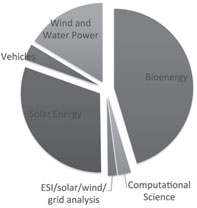
FIGURE 7.7: Peregrine use by area.
FIGURE 7.8: Peregrine utilization by node count.
Projects are binned into the six areas shown in Figure 7.7. Projects in Bioenergy, Solar, and Wind and Water Power are the largest consumers of Peregrine node hours.
Figure 7.8 shows the amount of Peregrine cycles used by jobs of different sizes. Jobs that use between 1 and 8 nodes consume the majority of time while larger node-count jobs up to 64 uniformly split the remainder.
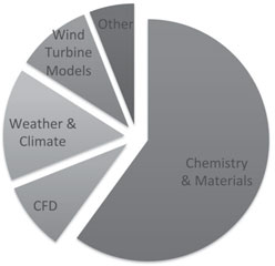
Figure 7.9 shows the breakdown of Peregrine use by discipline. Chemistry and Materials codes consume about 60% of Peregrine node hours.
FIGURE 7.9: Peregrine utilization by node count.
[1] M. J. Frisch, G. W. Trucks, H. B. Schlegel, G. E. Scuseria, M. A. Robb, J. R. Cheeseman, G. Scalmani, V. Barone, B. Mennucci, G. A. Petersson, H. Nakatsuji, M. Caricato, X. Li, H. P. Hratchian, A. F. Izmaylov, J. Bloino, G. Zheng, J. L. Sonnenberg, M. Hada, M. Ehara, K. Toyota, R. Fukuda, J. Hasegawa, M. Ishida, T. Nakajima, Y. Honda, O. Kitao, H. Nakai, T. Vreven, Jr. Montgomery, J. A., J. E. Peralta, F. Ogliaro, M. Bearpark, J. J. Heyd, E. Brothers, K. N. Kudin, V. N. Staroverov, R. Kobayashi, J. Normand, K. Raghavachari, A. Rendell, J. C. Burant, S. S. Iyengar, J. Tomasi, M. Cossi, N. Rega, N. J. Millam, M. Klene, J. E. Knox, J. B. Cross, V. Bakken, C. Adamo, J. Jaramillo, R. Gomperts, R. E. Stratmann, O. Yazyev, A. J. Austin, R. Cammi, C. Pomelli, J. W. Ochterski, R. L. Martin, K. Morokuma, V. G. Zakrzewski, G. A. Voth, P. Salvador, J. J. Dannenberg, S. Dapprich, A. D. Daniels, Ö. Farkas, J. B. Foresman, J. V. Ortiz, J. Cioslowski, and D. J. Fox. Gaussian 09, rev. a.1, 2009.
[2] G. Kresse and J. Hafner. Ab initio molecular dynamics for liquid metals. Phys. Rev. B, 47: 558–561, 1993.
[3] J. Michalakes, J. Dudhia, D. Gill, T. Henderson, J. Klemp, W. Skamarock, and W. Wang. The weather research and forecast model: Software architecture and performance. In G. Mozdzynski, editor, Proceedings of the 11th ECMWF Workshop on the Use of High Performance Computing in Meterology, Reading, U.K., 2004.
1 The Leadership in Energy and Environmental Design (LEED) Green Building Rating System serves as a nationally accepted benchmark for the design, construction, and operation of high-performance green buildings. To achieve LEED certification, a construction project shall achieve certain prerequisites and performance benchmarks within each of the following five areas: sustainable site development, water savings, energy efficiency, materials selection, and indoor environment quality. Projects are awarded Certified, Silver, Gold or Platinum certification, depending on the number of credits achieved. For more information, see http://www.usgbc.org/leed#certification
