
MOBILE TV SERVICES USING DVB-H TECHNOLOGIES
Just because something doesn’t do what you planned it to do doesn’t mean it is useless.
—Thomas Alva Edison
7.1 INTRODUCTION: DIGITAL VIDEO BROADCASTING TO HANDHELDS
DVB-H technology is designed to use the digital terrestrial TV broadcast infrastructure to deliver multimedia services to mobiles. It can use the same spectrum slots used by digital TV. The DVB technology for handhelds has been designed to meet almost all the objectives of delivering a TV service to handhelds, which include:
• broadcast service reaching potentially unlimited users,
• delivery of sufficiently large transmitted power so that the mobiles can work even within buildings,
• conservation of battery power used in receiving the TV service of choice,
• use of the terrestrial broadcast spectrum, which is being rendered free as a result of the digitalization of TV networks,
• robust coding and error correction to cater to highly variable signal strength conditions encountered in the handheld environment, and
• minimum infrastructure to roll out the TV services for mobiles. DVB-H can use the same infrastructure as DVB-T.
A DVB-H service can deliver 20–40 channels or more (depending on the bit rate) or up to 11 Mbps (typical) in one DVB-H multiplex, which can reach millions of viewers, being in a broadcast mode. The following are the options for configuring a DVB-H system:
• bandwidth modes of 5, 6, 7, and 8MHz;
• COFDM carrier modes 2K, 4K, and 8K; and
• modulation formats of 4QAM, 16QAM, and 64QAM.
DVB-H was standardized by the DVB and the ETSI under EN 302 304 in November 2004. Due to the evolving nature of the technology, there are new versions of the basic specifications that take into account the latest developments. The technology has been validated in a number of trials, including Helsinki, Pittsburgh, Oxford, Barcelona, and Berlin.
DVB-H is based on open standards and is compatible with DVB-T. It follows the IP datacast model and the entire network is end-to-end IP.
Digital video broadcasting using terrestrial transmission is a widely used technology with over 50 countries already having terrestrial transmissions in digital mode. Even in countries in which analog TV transmission is the norm, digital terrestrial transmission is rapidly being introduced and is replacing the analog terrestrial transmissions. In the process, spectrum is being freed up, as a single DVB-T multiplex can carry six to eight channels, which were earlier occupying one frequency slot each. An extension of these services to mobile devices has therefore been considered the most viable option by suitable modifications to the DVB-T recommendations, which have led to the DVB-handheld recommendations. DVB-T services are not straightaway suited to mobile devices, as the standards for DVB-T have been formulated for fixed receivers with relatively large roof-mounted antennas and no limitations on receiver battery power. These factors make the straight reception of DVB-T in a mobile environment, characterized by much lower signal strengths, mobility, and fading, unsuitable. The DVB-H standard, which addresses these factors through suitable enhancements to the specifications, becomes an ideal medium for mobile TV delivery.
The other factor that tilts the scale toward DVB-H is that the UMTS or 3G-based mobile TV services, which are unicast in nature, are not scalable for mass delivery. They have limitations in using the frequency spectrum and network resources to deliver multiple-channel broadcast television to large number of simultaneous users. To an extent these are being addressed by multicast services such as MBMS. However, pure broadcast television independent of the cellular network frequencies has very significant advantages.
The existing technology of digital audio broadcasting (DAB) is similarly not ideally suited, owing to the narrow transmission bandwidths possible and the need for spectrum and protocols for reliable multimedia delivery. The DMB system is an extension of the DAB standards that provides additional features for mobile multimedia. DVB-H, which is based on IP layer and IP datacasting of content packets, is a technology that has an advantage over DMB in this regard.
DVB-H is based on IP based transport. Video is typically carried using MPEG-4/AVC (H.264) coding of video signals, which can provide a QCIF coding at 384 kbps or less. Even a CIF video can be coded at sub-1 Mbps by using H.264 encoders. These encoders can work on real-time TV signals and provide MPEG-4/AVC-encoded output in IP format. As it is based on IP transport, DVB-H can support video and audio coding other than MPEG-4/AVC. Fundamentally as an IP transport, it ultimately can support any AV stream type. In addition to MPEG-4, Microsoft VC-1 coding format is set out in the DVB-H standards. The resolution and frame size can be selected by the service provider to meet the bit rate objectives. The data is then transmitted by using an IP datacast (Fig. 7-1).
In a typical DVB-H environment a number of TV and audio services may be encoded by a bank of encoders. All these encoders are connected by an IP switch to an IP encapsulator, which then combines all the video and audio services as well as the PSI and SI signals and EPG data into IP frames. The IP encapsulator also provides for channel data to be organized into time slices so that the receiver can remain active only during the times for which the data for the actively selected channel is expected to be on air (Fig. 7-2).
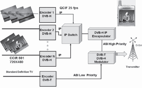
FIGURE 7-1 A DVB-H Mobile TV Transmission System
The IP encapsulator also provides a more advanced forward error correction code, which can deliver reliable signals in typical mobile environments. The data rate at the output of an IP encapsulator under DVB-H will in general be dependent on the modulation type used as well as the bandwidth available. Typically a DVB-H multiplex would be 11 Mbps of data, which when modulated could generate a carrier, e.g., 7–8 MHz. This compares with a 21-Mbps multiplex for DVB-T service in the VHF band. The effectively lower transmission rate for DVB-H is due to a higher level of forward error correction applied to make the transmissions more robust for the handheld environment.
The output of the IP encapsulator, which is in ASI format, is then modulated by a COFDM modulator with 4K (or 8K) carriers. The COFDM modulation provides the necessary resilience against selective fading and other propagation conditions. The DVB-T standard provides for 2K or 8K carriers in the COFDM modulation. The 4K mode has been envisaged for use in DVB-H as 2K carriers would not give adequate protection against frequency-selective fading and also provide for a smaller cell size owing to the guard interval requirement for single-frequency networks (SFNs). At the same time the 8K carrier mode has the carriers placed too close in frequency for the Doppler shifts to be significant for moving receivers. Hence the new mode of 4K carriers has been incorporated as part of the DVB-H standards. The 4K mode provides a better compromise between the cell size and the Doppler effects due to motion. A4K symbol interlever is also used in the modulation process. However, it should be recognized that the carrier mode actually used would depend on the frequency band employed, i.e., UHF band or L-band. The modulation used for each of the carriers can be with QPSK, 16QAM, or 64QAM.
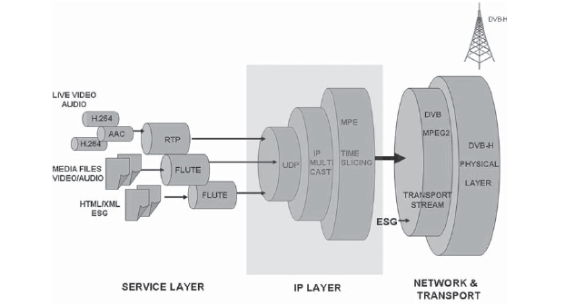
FIGURE 7-2 DVB-H IP Datacasting
The DVB-H standard provides for COFDM modulation, which is suitable for SFNs. The system uses GPS-based time clocks and time stamping to ensure that all the transmitters in a given area can operate maintaining time synchronism, which is needed for SFNs. This also implies that repeaters can be used in the coverage area at the same frequency and these repeaters serve to add to the signal strength that is received at the mobile.
7.4.1 Principles of the DVB-H System
Building upon the principles of the DVB-T standard and the digital audio broadcasting standards, the DVB-H standard adds functional elements necessary for the requirements of the mobile handheld reception environment. Both DVB-H and DVB-T use the same physical layer and DVB-H can be backward compatible with DVB-T. Like DVB-T, DVB-H can carry the same MPEG-2 transport stream and use the same transmitter and OFDM modulators for its signal. Between twenty to forty television and audio programs targeted for handheld devices can be transmitted in a single multiplex, or the capacity of a multiplex can be shared between DVB-T and DVB-H. In practice the bit rate for a DVB-H multiplex can range from 5 to 21 Mbps.
DVB-H provides additional support for mobile handheld reception. This includes battery saving through time slicing and increased general robustness and improved error resilience compared to DVB-T using multiprotocol encapsulation–forward error correction (MPE-FEC). In addition DVB-H broadcasts sound, picture, and other data using IPv6. The DVB-H can also be used for nonbroadcast frequencies.
The following are the basic attributes of a DVB-H system:
• encoding of audio, video, data, or files;
• use of IP datacasting for delivery of data to multiple receivers;
• organization of data into a group of packets for each channel (time slicing);
• insertion of appropriate signaling data for carrying the DVB-H stream information;
• application of forward error correction and multiprotocol encapsulation;
• GPS time stamping for single-frequency networks; and
• modulation using QPSK, 16QAM, or 64QAM and 4K (or 8K) COFDM carriers with frequency interleaving.
7.4.2 Functional Elements of DVB-IP Datacast Model
DVB-H uses IP datacasting (referred to as IPDC). The process involves packaging of digital content into IP packets and then delivering these packets in a reliable manner. The IP platform does not restrict the type of content that can be carried and hence the IPDC is suitable for carrying live video, video downloads (via file transfer), music files, audio and video streams (in streaming format), Web pages, games, or other types of content.
Compared to unicast IP networks the IPDC provides significant advantages as the broadcast networks can reach millions (unrestricted number of users) and are inherently high speed, which is available to all users.
The use of IP as the base technology has the advantage that the data including content can be handled by the same protocols and devices that have been used extensively on the Internet and for which inexpensive devices and management techniques are available. The transmission medium is also neutral to the type of content being carried, which can be live TV, audio and video files, or HTML/XML Web pages.
The data to be broadcast consists of two types—the broadcast content and the service description, such PSI/SI data and an electronic service guide. In addition the data may contain rights management information for access or subscription to the content. The IP layer provides sockets through which information of each type can be transmitted.
7.4.3 Time Slicing
One of the features that distinguishes DVB-H from DVB-T is the feature of time slicing of the channel data on the final multiplex. In the case of DVB-T a number of channels are also multiplexed together (e.g., six to eight services in a multiplex of 8 MHz). However, at the multiplexing level the packets for different channels follow sequentially. As a result of the very high data rate, the receiver for each channel needs to be active all the time as the packets are continuously arriving.
In the case of DVB-H the IP encapsulator gives the full capacity of the multiplex for a limited time to only one channel. Hence packets for the channel all arrive in a bunch, one after another, during this time. While this slot is allocated to the channel, there are no packets from other channels. This allows the receiver, if it needs only one channel, to become active only during the time the packets for the channel are grouped together (i.e., during the time slot allocated to the particular channel). At other times the receiver (tuner) can be switched off so as to conserve power. It needs to wake up just prior to the planned arrival of the designated channel slot (in practice 200 msec is required for synchronization). This allows the mobile receiver to be in power-off mode for signal reception for up to 95% of the time depending on the number of services multiplexed. In terms of time, the data for periods of 1–5 sec is delivered in a single burst. If the channel data rate is 1 Mbps (for example) the receiver needs to buffer 5 Mbits of data for a 5-sec “inactive time.” Alternatively, for a TV service running at 25 fps, the receiver would buffer 125 frames of data. These buffered frames are displayed normally and the user is not aware that the receiver is inactive (Fig. 7-3).
The amount of data sent in a burst is equal to one FEC frame. This may be 1–5 Mbits. When the receiver is not receiving the wanted burst of data, the tuner contained in the handheld device is “inactive” and therefore using less power.
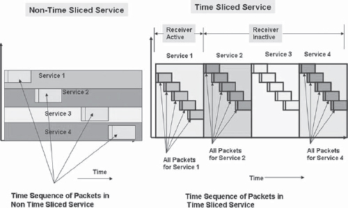
FIGURE 7-3 Time Slicing in DVB-H
There are alternative uses for the inactive period, however. For example, the receiver may measure the signal strength from nearby repeaters to work out the handover to a more appropriate transmitter or repeater.
It is possible to place time-sliced (i.e., DVB-H) and non-time-sliced (DVB-T) services in the same multiplex.
7.4.4 Switching Time between Channels and Transmitter Parameter Signaling (TPS) Bits
One of the issues that arise due to the receiver being in the power-off mode for a significant portion of the time is the time needed to switch TV channels on the mobile. In order to reduce the search time and enable “fast service discovery,” the signaling bits of the DVB-T stream carry information about the DVB-H streams as well. The DVB-T signaling frame consists of 68 TPS bits of which only 23 are used for DVB-T parameters. When DVB-H is carried on the same multiplex some of the unused TPS bits are used to carry information about the DVB-H. The following types of information are carried by the TPS bits:
• whether DVB-H is present in the DVB multiplex,
• 4K or 8K mode,
• use of time slicing, and
• use of forward error correction.
The added TPS bits in the signaling stream help in fast retuning of the newly selected channel as well as handoffs in the mobile environment as the DVB-H receiver is aware of the status of the entire transmit stream.
7.4.5 MPE-FEC
The reception by handheld devices is quite different from that by fixed terrestrial antennas. First, the antennas themselves are quite small and have low gain. Second, the handset being in a mobile environment, the received signal can undergo rapid fluctuations in received power.
Despite the robust physical layer using COFDM transmission in which the selective fading is reduced, owing to the use of single-frequency networks and the received signals being reinforced by all sources, reflected and direct, there is additional protection needed in the form of forward error correction.
The video and audio data in a DVB-H environment is delivered using IP datacasting. This implies that the data is encapsulated with IP headers and transmitted in the same way as it is over the Internet. However, the radio environment is not as friendly as the Internet and is subject to a high error rate due to signal level variations, interference, and other transmission effects. This requires the data to be well protected.
The data protection is done in the case of DVB-H using the technology of forward error correction. The IP encapsulator carries out the additional functions of MPE-FEC. The FEC is implemented at the link level (i.e., before the data is encrypted). It should be recognized that the DVB-H uses the physical layer of the DVB-T (i.e., the COFDM modulation). The COFDM is very robust and provides good reception even under conditions of multipath transmission. The MPE-FEC provides a further degree of protection over and above the COFDM.
The data coming from the encoder is put into an FEC frame, which is prepared by using code RS(255,191). The frame consists of up to 1024 rows. Each row has 191 columns (each column being a byte) of IP data and 64 columns of FEC data in the form of parity bytes. Each row thus represents 191 bytes of IP data, which is converted by adding the forward error correction parity bits to 255 bytes. If 1024 rows are used in the frame, then one frame contains 191 Kbytes of IP data and 255 Kbytes of transmitted data. This can also be represented as 1.528 Mbits of IP data and 2.040 Mbits of transmitted data (Fig. 7-4).
For an encoder running at 384 kbps (48 Kbytes per second), one FEC frame can carry 3.97 sec of data, which is transmitted as one burst. This will contain approximately 100 frames at a 25 fps coding rate. The use of the FEC reduces the signal-to-noise ratio required to receive the signals by a factor of up to 7 dB. This gives a significant resilience to the handheld devices in receiving DVB-H transmissions.
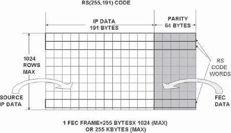
FIGURE 7-4 MPE-FEC Frame Structure
DVB-H is a multimedia transmission system that is expected to serve multiple applications and file formats. This can include audio and video streaming, file transfer, electronic service guide, HTML, or XML data. The standard has therefore been designed with an appropriate layered protocol structure to carry out these tasks over the IP datacast layer. This is specified through its protocol stack with a number of layers.
The physical layer provides an MPEG-2 transport and COFDM-based transmission of the content. These specifications were finalized by the ETSI in November 2004. The only change in the physical layer from that in the DVB-T systems in use is the use of the 4K mode in COFDM transmission, which is better suited to delivery to mobiles and TPS.
The IP datacasting layer allows data content to be delivered in the form of packets over the DVB-H physical network. This uses the UDP/IP stack at the network layer level and the MPE at the data-link level (Fig. 7-5).
The video and audio data, which has been encoded using H.264/AVC, is streamed using the underlying UDP/IP layers in the application layer. The signal is also carried using the network and data link layers.
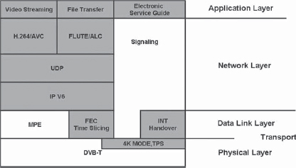
FIGURE 7-5 DVB-H Protocol Stack
Datacasting in DVB-H is defined based on IPv6 (or Internet version 6). This provides more flexibility in the management of the application and is compatible with the future requirements of the IP applications, which may require interactivity and addressing of every mobile device with attendant IPv6 security and features.
The DVB-H standard has been designed in a manner that enables operation of the video broadcast systems in a very flexible manner with multiple configurations possible either with existing digital TV networks or as new installations. It also needs to be borne in mind that while the DVB-T transmissions are meant for relatively large antennas mounted on rooftops, the DVB-H needs to reach very small antennas in the mobile environment. There is also a requirement that the transmissions reach inside buildings. Owing to these factors the effective isotropic radiated power (EIRP) needs to be much higher for DVB-H systems. The power transmitted also depends on the antenna height. As an example, if the EIRP required for a mobile with a minimum power threshold of –47 dBm in a range of up to 5 km is 46 dBm EIRP (20 W) for a 120-m antenna height, then an antenna of 25 m will require approximately 70 dBm of EIRP (10 kW).
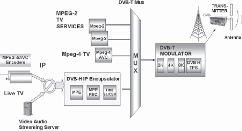
FIGURE 7-6 DVB-H on a Shared Multiplex
DVB-H technology has been designed to share the existing infrastructure of DVB-T, which is being rolled out for the digital TV implementation. Hence sharing of the DVB-T network has been given a special consideration in the specifications framework.
DVB-H can be operated in three network configurations:
1. DVB-H shared network (sharing the MPEG-2 multiplex): In a DVB-H shared network the mobile TV channels after IPE (IP encapsulation) share the same DVB-T multiplex along with other terrestrial TV programs. The terrestrial TV programs would be coded in MPEG-2, while the mobile TV programs are in MPEG-4 coding and IPE. The multiplex combines these into a single transmit stream, which is then transmitted after modulation (Fig. 7-6).
2. DVB-H hierarchical network (sharing DVB-T network by hierarchy): In a hierarchical network, the modulation is hierarchical with the two streams, DVB-T and DVB-H, which form a part of the same modulator output. (Fig. 7-1 shows the sharing of the network by hierarchy.) DVB-T is modulated as a low-priority stream and DVB-H as a high-priority stream. In the case of high priority, the modulation is more robust (e.g., QPSK) as opposed to low priority, which may be 16QAM. The lower “density” modulation scheme provides higher protection against error as opposed to higher density schemes.
3. DVB-H dedicated network: The DVB-T carrier is used exclusively for DVB-H transmission. In a dedicated network, the COFDM carrier will be used exclusively by the mobile TV and audio channels as an IP datacast with the MPEG-2 envelope. Dedicated networks are generally used by new operators who do not have existing digital terrestrial broadcasting (Fig. 7-7).
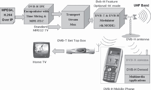
FIGURE 7-7 Reception in DVB-H Shared Environment
7.8 DVB-H TRANSMITTER NETWORKS
The DVB-H implementation guidelines provide for a reference receiver (ETSI 102 377), which serves as a benchmark for system design. The design provides for a C/N of 16 dB. Indoor coverage typically would need to take care of transmission losses of 11 dB or more. Applying the design parameters, a city of the size of Paris or New Delhi will typically require 17–20 transmitters.
7.8.1 Single-Frequency and Multifrequency Networks
Depending on the area required to be covered, the DVB-H systems may be engineered with single-frequency networks or may need multifrequency networks.
7.8.2 DVB-H Cell
A small town can be covered by a single DVB-H “cell” comprising one transmitter and 10–20 repeaters. The repeaters are required to cover the areas in shadows due to the geographical terrain. A repeater is essentially a minitransmitter with a high-gain antenna for receiving the signals from the main transmitter. Due to the SFN requirements, the above topology cannot be extended beyond a certain range, as the time delay in reception from the main transmitter will result in the retransmitted signal being out of phase with the main transmitter.
The number of repeaters in a DVB-H cell is determined by the power of the main transmitter as well as the height of the tower. A very high tower reduces the shadow areas and the number of repeaters required for a given geographical area.
7.8.3 Single-Frequency Networks
Larger areas (e.g., a city or around 50 km in radius) can be covered by using an SFN. The SFN comprises a number of DVB-H cells, each with a transmitter and a number of repeaters. The transmitters receive the signal in the form of an MPEG-2 transmit stream, which originates from the IPE (Fig. 7-8). An IP network is used to distribute the signal to all the transmitters in a given area. All the transmitter sites thus receive the same signal, which is time stamped by the GPS-based clock. At each transmitter site the COFDM modulator synchronizes the signal using a GPS time reference so that all transmitters transmit identically timed signal despite their geographical location. The number of repeaters used with each transmitter can be increased to provide indoor reception, leading to the nomenclature of dense SFN.
Figure 7-9 shows the typical SFN correlation distances.
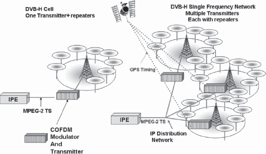
FIGURE 7-8 DVB-H Single-Frequency Networks
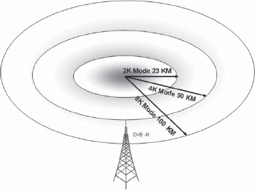
FIGURE 7-9 SFN Correlation Distance. All distances are based on 16QAM modulation with 1/4 guard interval for COFDM
When the area of required coverage is large (e.g., an entire country of several hundred kilometers), sourcing a signal from a single IPE is not practical due to time delays in delivering signals to all transmitters. In such a case, transmitters beyond a certain range use different frequencies. Based on the topography, five or six frequency slots may be needed to cover a country. In such cases it is usual to distribute the signals using a satellite so that hundreds of transmitters can be covered, including in remote areas.
7.9 TERMINALS AND HANDHELD UNITS
DVB-H provides a technology to successfully broadcast live TV signals by encoding the content and IP datacasting the packets after applying robust FEC. However, the terminals for reception being mobile phones (e.g., Nokia N92), they need to support the necessary reception antenna for receiving the signals. Single-chip tuners and DVB-H decoders provide an efficient way to receive mobile TV on handsets that provide the TV application as an “add on” to the “normal” functions of the set, which may be voice and data based on the use of 3G networks. The DVB-H is thus not an “in-band technology” like MBMS, which uses the same spectrum as the 3G services.
DVB-H receivers are in most cases mobile phones that have a return channel via the underlying 2G or 3G networks, unlike normal broadcast receivers. This implies that the broadcasters can use these features to have additional control over the sale of programs that are broadcast, content protection, and digital rights management. The need to incorporate these features has led to slightly different approaches to the manner of content protection or handling of return channel interactivity. The different approaches have been reflected as DVB-H implantation profiles and are an area of future convergence of standards.
7.10 DVB-H IMPLEMENTATION PROFILES
The DVB-H standards specify the use of the IP datacast as the model for the delivery of the content. As a part of such implementation DVB-H has also specified the manner in which various types of interactive content are to be delivered.
Additional features that need to be specified for a DVB-H service are:
• sale of programs through return channel interactivity and
• encryption of content for broadcast level security and application of digital rights management (DRM) on content itself for its storage and later use.
There are three approaches to content security.
The first approach is that broadcast security be provided by traditional conditional access systems suitably modified for the mobile environment. This leads to handsets that are proprietary to specific networks.
The second approach is to use a common encryption at the transmission level such as ISMAcrypt and use either proprietary or open DRM at the content level.
The third approach is to use an open encryption such as IPsec at the broadcast level and also use an open DRM 2.0 for content protection.
The second and third approaches lead to the broadcast system being uniform and handsets deployable in any operator network.
The topics of interactivity and digital rights management are of considerable importance and are covered in Chaps. 15 and 16 of this book.
Aworking group called the DVB-CBMS (CMBS stands for Convergence of Broadcast and Mobile Services) has formalized the audio and video formats that should be used and the format of the ESG (electronic service guide). It is also responsible for giving recommendations on service protection and content protection. The CBMS standards were released by the DVB in December 2005.
The mode of delivery is covered by the DVB-CBMS of the DVB-H specifications. Each channel is delivered as an IP carousel, which carries the data for the particular time slice. The mode of delivery of interactive content follows a similar mechanism and is in fact derived from the broadcast world, where unidirectional systems such as DTH or digital cable provide “interactivity” by providing an IP data carousel that is transmitted continuously for carrying headlines, weather information, magazines, etc., which can be downloaded by the users by pressing a button on their remote. There being no return path, the information demanded is simply picked off from the data carousel. The DVB-CBMS is a multicast file delivery system, which has its origin in the similar use of carousels to carry data files. The DVB-CBMS is used to deliver pictures, games, text, ring tones, or other data.
The use of CBMS is supported largely by the broadcast industry, which has been using these technologies for over 2 decades in satellite digital TV and DTH systems. The standards based on CBMS also envisage the use of derivatives of traditional encryption systems for content protection and access control. Examples of these types of encryption systems are Irdeto Access, Viaccess, Mediaguard, and Conax. These encryption systems are based on symmetric key coding and require the use of a corresponding smart card or embedded key in remote handsets.
The drawback of such a content security scheme is that once an operator selects one type of encryption system for encryption of content (say Irdeto Access) the handsets used in the network cannot work seamlessly in other networks (e.g., those based on Viaccess or Conax). This has been viewed as a potential disadvantage particularly by those in the mobile handset manufacturing industry, which sees free interoperator roaming capability as a key to the growth of the industry (Fig. 7-10).
The above approach of the operators is somewhat akin to the replacement of a set-top box by the decrypters and decoder functions in the mobile TV. In this type of implementation the mobile sets can still have additional interactivity via 3G networks.
Interactivity using the carousel-based technology has been demonstrated in various trials. In the DVB-H pilot project in Berlin conducted by T-Systems in 2005, the interactivity was provided by “MiTV,” which is an API for interactive services. The data carousel using “FLUTE” (file delivery over unidirectional transport) was 50 kbps and provided pictures and text synchronized to the video content. The service also used an ESG client for the ESG service that was compliant with the DVB-H CBMS ESG.
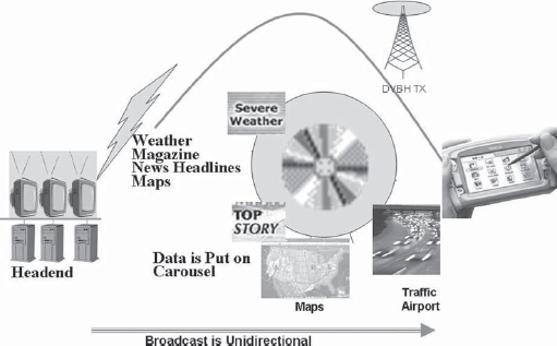
FIGURE 7-10 DVB-H Interactive Content Transmission via Data Carousel. Users can view interactive content by selection on their mobiles
The concept of open-air interface has been proposed by Nokia and others. In the “open-air” architecture the broadcast network is based on open standards that create interoperability among various operators and mobile handsets. This standard is known as the Open Mobile Alliance (OMA)/BCAST. The content security is by open encryption (IPsec) and open standards-based rights management (OMA DRM2). The network uses the mobile 3G for the return path through which interactivity can be provided (Fig. 7-11). The OMA BCAST provides an open framework independent of the transmission technology such as DVB-H, DMB-T or others.
The open-air interface provides specifications at the radio and application levels for DVB-H, IP layer protocols, electronic service guide, payment and purchase protection, as well as A/V coding carried in the DVB-H stream. This permits different networks and applications from different operators to connect to each handset.
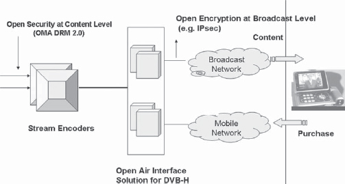
FIGURE 7-11 Open DVB-H Solution
The interactivity in the open-air interface networks can, for example, be with the Web site hyperlinks that are accessed via the 3G networks.
7.12 ELECTRONIC SERVICE GUIDE IN DVB-H
Analogous to the DVB-H interfaces (CBMS and OMA/BCAST), the ESGs also have different implementation based on the implementation interface selected.
The implementation profiles for the ESGs are still being developed and the profiles available today depend on the operator and the implementation interface selected.
For the OMA/BCAST-based systems, Nokia has come out with its implementation profile. As per this profile, the ESG supports pay-per-view and interactive links. A single ESG can be used for multiple operators, including individual operator guides.
The CMBS ESG profiles are still operator specific and implementations differ based on the parameters and profiles selected by the operator.
7.13 DVB-H PILOT PROJECTS AND COMMERCIAL LAUNCHES
DVB-H systems have been extensively tested in a number of pilot projects spanning America, Europe, and Asia. These pilot projects have demonstrated the suitability of all elements of the DVB-H standard, including the source coding, IP datacasting, and COFDM reception, as well as confirming the suitability of handsets under varying transmission conditions.
In addition, commercial licenses for launch of services based on DVB-H were granted in Italy (La3) and Finland (Digita) to coincide with the FIFA World Cup 2006. Europe’s first commercial DVB-H service was launched by La3 in Italy in June 2006.
7.13.1 United States of America
The American digital TV scene is dominated by the extensive use of the ATSC transmission system on which over 1200 stations are now active. The DVB-H standard, which relies on the basic DVB-T transport as a physical layer, can thus not be added onto the existing ATSC digital TV networks.
However, the technology can be deployed by creating an independent DVB-H transmission system without sharing the transmission DVB-T or ATSC MPEG-2 multiplex.
Modeo (formerly Crown Castle Media) has pioneered the DVB-H trials in the United States and has also launched a commercial service using 5-MHz capacity in the L-band. The trials were held in Pittsburgh, followed by the launch of the commercial service. The Crown Castle network uses satellite distribution as a means to feeding the L-band transmitter network across the United States.
The commercial launch in 2007 involves a nine-transmitter network operating on single-frequency mode. Crown Castle owns 5MHz of spectrum in the L-band (1670–1675 MHz). DVB-H is primarily a terrestrial transmission standard and as Crown Castle already owns and operates over 10,000 sites for wireless communications, it is in a position to rapidly rollout its DVB-H services under the name Modeo using its entire network.
The rollout features video coded in Windows Media 9 (WMV9) format with QVGA resolution and 24-fps delivery, making for a bit rate of approximately 300 kbps per video stream. It uses Windows Media DRM 10. The initial bouquet comprises about 10 video channels and 24 audio channels that can be received by cell phones, PDAs, and other portable devices. The system uses Windows CE-compatible receivers. The backbone connectivity for the entire network of terrestrial transmitters is provided by the satellite AMC-9, which is located at 83W.
The service uses the DVB-H-compatible Nokia handset N-92 (Fig. 7-12).
Modeo will also be the world’s first mobile broadcast network to support “pod casting” (distribution of recorded audio or video programs over Internet protocol).
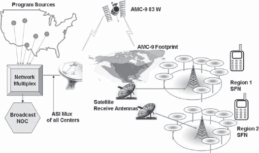
FIGURE 7-12 DVB-H in the USA—the Modeo Network
DVB-H Commercial Trials
7.13.2 Europe
The ETSI has adapted the DVB-H standard for Europe, which has also adopted the DVB-T standard for digital television, making the potential launch of services straightforward. Commercial DVB-H services have been launched by 3 Italia and a number of trials have been concluded, as given in Table 7-1. Many of these commercial trials are now being developed as full-fledged DVB-H services. After the Broadcast Mobile Convergence (Bmco) trial in Germany, four telecom operators (T-Mobile, Vodafone, O2, and E-Plus) launched a DVB-H trial in June 2006 coinciding with the FIFA 2006, which will be developed into a full-fledged launch. Digita in Finland is also launching DVB-H services.
7.14 EXAMPLE OF A DVB-H TRANSMISSION SYSTEM FOR MOBILE TV
A number of vendors are now providing complete solutions for DVB-H broadcasting. A complete solution would consist of
• MPEG-4/WMV9 audio and video encoders,
• DVB-H IP encapsulators,
• DVB-H transmitter system,
• gap fillers (repeaters),
• GPS receiver system.
An example of the system for encoding, IP encapsulation, and transmission of mobile TV using the DVB-H product line from Unique Broadband Systems is given below for purposes of illustration.
7.14.1 Encoders for Mobile TV
The video is encoded using MPEG-4/H.264 encoders, which convert a standard definition full-resolution CIF or QCIF.
A typical real-time encoder used for mobile TV applications using DVB-H as a medium of transmission would have the capability to encode QCIF or full-resolution to MPEG-4 and provide an IP output for further IP encapsulation. An example is the MPEG-4/DVEN 1000 encoder from Unique Broadband Systems.
The MPEG-4/H.264 encoder is used for real-time encoding and broadcasting of live video and audio or audio analog signals into MPEG-4/H.264-encoded streams. The encoder can be used in a broad variety of applications from file encoding and streaming of prerecorded content to real-time encoding and broadcasting of live video sources. It can cater to unicast/multicast live video streaming, record to file, and streaming of prerecorded encoded content. Some examples of configuration schemes are:
• two channels, CIF, 30/25 fps, 340–500 kbps;
• two channels, 720 × 480, 30 fps, 2 Mbps;
• one channel, 1280 × 720 HDTV, 20 fps, 2 Mbps.
7.14.2 IP Encapsulation
IP encapsulation is the next stage in the process of preparing the DVB-H signals for transmission. The IP encapsulator carries out multiple functions, including combining of the various services, integrating the PSI/SI data streams, providing time-slicing control, and MPE encapsulation.
A typical example of IP encapsulator from Unique Broadband Systems is the DVE 6000 IP encapsulator with features enumerated below:
1. user-specified Reed Solomon encoding for each service;
2. dynamic burst scheduling to maximize bandwidth;
3. ASI output–adjustable bit rates;
4. accurate time-slicing control;
5. seamless integration into SFN;
6. constant and variable bit rate IP source support;
7. Web and SNMP control;
8. network management GUI;
9. intuitive user interface;
10. IPv4/IPv6 input streams support;
11. NIT, INT, PAT, PMT table generation;
12. SI/PSI table scheduling and processing according to the DVB-H intersection timing requirements and insertion into the transport stream;
13. 23–128 services (depending on hardware configuration);
14. up to 8 Mbps throughput;
15. compliance with
• ETSI EN 301 192,
• ETSI EN 300 468,
• ETSI EN 300 744,
• ETSI TS 101 191,
• ISO/IEC 13818-1,
• ISO/IEC 13818-6.
The IP encapsulator provides an ASI output for the modulator.
7.14.3 Modulation
The RF signals are modulated to COFDM by the modulator. The modulator in the case of DVB-H has additional functions to perform over its basic function, i.e., modulating the ASI stream to COFDM.
The first is hierarchical modulation as per DVB-H, in which two MPEG-2 carriers can be generated (for DVB-H and DVB-T). Hierarchical modulation can help transmit the same channel for mobile handhelds as well as the fixed rooftop antennas.
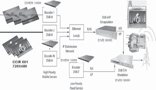
FIGURE 7-13 An Implementation Example of a DVB-H Mobile TV Transmission System (Courtesy of Unique Broadband Systems)
The modulators can be used to set the output bandwidth to 5, 6, 7, or 8 MHz, giving flexibility in the transmission plan or the country-specific implementations.
An example is the DVB-H Modulator DVM-5000 from Unique Broadcast Systems, with the following specifications:
• 30 MHz to 1 GHz RF output,
• full hierarchical mode support,
• SFN and MFN support,
• near-seamless switching between inputs,
• superior MER performance,
• linear and nonlinear digital precorrection,
• Web browser remote control,
• SNMP remote control, and
• FULL DVB-H support.
7.14.4 DVB-H Transmitter and Other Components
ADVB-H transmitter system with power ratings of up to 200 W is the DVB-H-TX50/100/200 from Unique Broadband Systems. It also has SFN adopters (e.g., DVB-T/DVB-H DVS 4010 SFN adopter), DVB-T/DVB-H modulators (DVM 5600), and a GPS receiver system (Fig. 7-13).
DVB-H transmitters and repeaters are available from a number of vendors. An example is the Atlas DVB-H solid state transmitter from Harris with power rating of 9 kW and Atom DVB-H repeater with a rating of 5 to 400 watts.