
8 Sound mixers
Part 2
Inputs and connections
In dealing with the inputs to a mixer, or indeed any other connections, we must make clear a most important distinction which exists between professional and non-professional sound equipment: professional equipment invariably makes use of what is termed balanced wiring for connections between different items. Domestic equipment, on the other hand, almost always uses unbalanced wiring. Semi-professional systems may use either or both.
In balanced wiring there are three conductors: two carry the audio signal and one is for an earth connection, the latter often being in the form of a ‘screen’ of braiding. Care is taken to ensure that the two signal wires are as similar as possible to each other in electrical terms, which also means that they are geometrically symmetrical. The point about this arrangement is that if there is a nearby source of electrical interference, such as a mains cable carrying a substantial current, first the screen tends to ‘protect’ the signal wires. Secondly, if any interfering voltages are generated in the signal wires then, because of their close similarity in electrical characteristics, these voltages will be equal and will then tend to ‘cancel out’. Some microphone cables are made up into what is known as ‘star quad’ form. Here there are four conductors, twisted around each other and then enclosed in a screen. Opposite pairs of the four conductors are connected together and the result is a cable which is highly immune to the effects of interference.
With unbalanced wiring, where there is, for example, a central conductor surrounded by a braid screen, the ‘cancellation’ referred to above cannot take place, although the screen gives some protection. However, such cables can be perfectly satisfactory for short lengths, such as in the links between a domestic cassette player and an amplifier, when 15–20 cm of connecting wire is all that is needed. Furthermore, the audio signal voltages in such instances are much greater than those in a microphone cable and are therefore likely to exceed greatly any interfering signals.

Figure 8.4 Pin arrangements on XLR plugs and sockets
So, at the input to a mixer we shall hope to see balanced sockets. These will most likely be what are known as XLR sockets. Figure 8.4 shows the pin/socket arrangement when the connector is viewed end-on. Plugs have pins which are recessed into the housing; sockets have three holes, the ends of which are flush with the front of the housing.
A suitable microphone will therefore have an XLR socket (male) incorporated in it; the cable will have an XLR female plug at the microphone end and a male plug at the mixer end, while the mixer inputs will be female. The screen connection at the microphone end will continue so that the microphone case is also a screen. (Note that we have used the terms ‘plug’ and ‘socket’ somewhat arbitrarily here, implying that a connector is a plug if it is on a cable and a socket if it is not.)
The terms ‘male’ and ‘female’ can, in some cases, be very confusing. Basically if there are pins it is male. Sometimes the distinction can be far from clear!
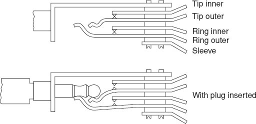
Another important type of connector is the so-called PO (= Post Office) jack. Although devised about a century ago, the design was so good that PO jacks have survived with little modification to the present day. There are variants – some for mono and some for stereo. Basic mono versions are shown in Figures 8.5 and 8.6. Socket connections are shown in Figure 8.7.
Proper stereo jacks have a second conducting band and the sockets are modified accordingly.
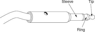
Figure 8.5 A PO (‘Post Office’) jack
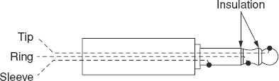
Figure 8.6 Mono PO jack wiring
The British Post Office had responsibility for UK telephone services up to about 1981. After that, British Telecommunications (BT) took over, but things like the jacks referred to here at still known as ‘PO’ or ‘Post Office’ jacks.
We should emphasize that there are significant – but not always obvious – differences between the true PO jacks and the domestic versions. For example, the former are tapered, the latter are not, so that there is an inherent incompatibility between the two. Any attempt to use one type with the other may result in physical damage at the worst, and poor contacts at best. (Information about wiring conventions is given in the ‘Data’ section near the end of the book.)
An important practical point about PO jacks is that they must be clean. They are very reliable – otherwise they wouldn't have been in professional use for so long – but they are made of brass and this is a metal that tarnishes easily. Any kind of tarnish on a metal is likely to have a rectifying action – which means that there is a tendency for an alternating current to become unidirectional and action of this kind can easily convert any tarnished contact into a crude radio receiver. As a result, unwanted radio pick-up from a high power medium or long wave transmitter in the vicinity – up to 15 miles or more – can produce quite good but unwanted reception of radio programmes in a recording.
Consequently, an occasional cleaning session with any good proprietary brass cleaner is very strongly recommended. The semi-professional type, with a chrome surface, isn't liable to tarnish.
Quite a lot of useful information about types of plug and socket can be gained from the study of professional and semi-professional catalogues, the latter being readily available at high street bookshops.
Equalization
Some readers may prefer to see the graphical representation of the types of EQ outlined in Part 1 of the chapter.
Bass lift/cut
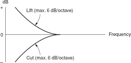
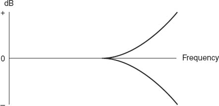
This is also known as l.f. (= low frequency) lift/cut. Figure 8.8 shows typical curves.
In Figure 8.8, the maximum rate of lift or cut is given as ‘6 dB/octave’. This means that on the steepest part of the curve, when the control is set to maximum lift or cut, each doubling or halving of the frequency (i.e. a change of one octave) changes the level by 6 dB. Perhaps we should try to make this a little more meaningful with an example. Let's suppose that we have bass cut selected and the frequency below which it is going to be effective is 120 Hz. Now suppose that there is an annoying 50 Hz mains hum. Can we reduce it with the bass cut?
One octave below 120 Hz is 60 Hz and the level will then be 6 dB lower. Without going into detailed calculations, it can be seen that the 50 Hz hum will be reduced by only a little more than 6 dB. We said in Chapter 1 that a reduction of 10 dB is subjectively equivalent to roughly halving the loudness, so in this case the bass cut will probably do little to reduce the effect of the hum. Worse, it may adversely affect the character of the speech or music. A bass cut control may be very useful in other ways, but what we are saying is that 6 dB/octave is not necessarily going to be useful in trying to eliminate certain unwanted noises.
Top lift/cut
This is also known as treble or h.f. (= high frequency) lift/cut, and is illustrated in Figure 8.9.
Again, the likely maximum slope will be 6 dB/octave.
Presence lift/cut
This is sometimes called m.f. (= mid-frequency) presence. Figure 8.10 suggests that the maximum amount of lift or cut is about 15 dB. This may not always be the case – the manufacturer's manual should always be consulted for information of this kind.
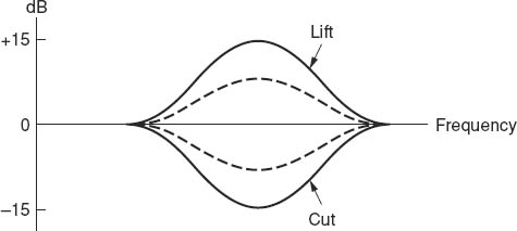
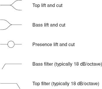
Figure 8.11 Symbols used for EQ controls
The symbols used on mixers have become more or less standard, with usually only minor variations from one manufacturer to another. Figure 8.11 shows the commonly used ones.
Filters
We probably don't need to have graphs but we can state that the slope of bass and top filters is typically around 18 dB/octave and if we apply this kind of slope to the hum problem above we can see that a steep filter is likely to be much more use. At the same time, of course, there is a risk of deterioration of wanted material, so care and compromise have to be used. Filters, except on the biggest and most expensive mixers, usually have fixed characteristics and are simply switched in or out.
Other audio filter devices include:
• Graphic Equalizers. These consist of a largish number of separate controls, each one varying the level of a band of frequencies. The range of level is often from –15 to +15 dB. On smaller units there are eight such controls, each one covering an octave. Bigger ones might have thirty-two controls, each handling a third of an octave. The controls have slide knobs on the front of the unit so that they give the appearance of a frequency response graph – hence the name ‘graphic equalizers’.
They are almost always add-on units. That is, they aren't normally built into a mixer. Instead, they are plugged into insert points.
• Parametric Equalizers. I've never been sure how they got their name! They don't equalize parameters. They're basically filters which act over a narrow band, like each part of a graphic equalizer, but the band is continuously variable in frequency, width and height (or cut). One very good instance of their use is to remove an unwanted steady note, such as line-up tone which is being picked up from somewhere. The equalizer is set to lift and then the frequency is swept steadily until the unwanted frequency is lifted. At that point the lift is changed to cut, and with any luck the interference is drastically reduced without, hopefully, serious effects on the rest of the programme sound.
Public Address and Foldback (PA and FB)
These are both loudspeaker feeds taken from some point in the mixer, such as one of the channels or, more commonly, from a group of channels. The basic difference between them is as follows:
• PA is for the benefit of a studio audience. A good example is in a television sitcom, where an audience can laugh at appropriate places, this being picked up by microphones and becoming part of the show. (Canned laughter doesn't ever sound convincing, in my view!) Also, the presence of an audience can encourage the performers – there's nothing like a live audience to bring out the best in any actor, comedian or musician. Now obviously this is only going to work if the audience can hear the dialogue, but to preserve some appearance of reality the actors in a sitcom will generally have to speak in normal voices – and they won't be heard by much or all of the audience unless the audience has a loudspeaker feed of the dialogue.
• FB, on the other hand, is for the benefit of the performers. For instance, and again to take a fairly typical television situation, although this can apply equally to radio, there is a largish band in the studio. It's important for the different musicians to hear other sections of the band, and the easiest way of doing this is to let each section or individual have a foldback feed of the sections that are most important to them. If it's visually acceptable, then headphones can be used for the foldback. Alternatively, discreetly placed loudspeakers can be used. In a television play the foldback of, say, important sound effects must be from loudspeakers.
The ‘Tone’ switch in Figure 8.3
There is no point in careful monitoring at the mixer if, say, a tape recorder connected to the mixer's output is set to the wrong record level. A very useful – one might say, essential – facility on any good mixer is the ability to send a known test signal to the recorder first. In the professional and semi-professional world, this signal is known as ‘line-up tone’ or ‘tone’ for short. It consists of a sine-wave signal having a frequency of about 1000 Hz (the exact frequency is not critical) and an accurately defined level, or voltage. This is usually zero level, referred to in Chapter 6, Part 2, where it is stated that this corresponds to 0.775 V. In the mixer an internal circuit generates the tone and when the switch shown in Figure 8.3 is operated then the first thing is that the meter will indicate zero level (‘4’ if it is a PPM) and the loudspeaker will emit a 1 kHz note.
Assuming there is some kind of meter on the recorder, this should show that the record level control is correctly set. (It may be necessary to record several seconds of the tone and then play this back to check that the machine has been set correctly.) It is standard practice on professional tape machines to record a length of tone on the tape and then follow this by a few seconds of silence before the recording proper. This allows a check on replay settings no matter on what machine the tape is replayed.
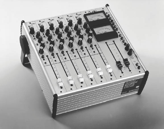
Figure 8.12 A small professional sound mixer (courtesy Audio Developments Ltd)
Talkback
This is the simplest of communication systems. Many mixers, even quite small ones, incorporate a microphone. Operation of a switch somewhere on the unit connects the output of this to a presenter or performer(s). Typically a presenter, with his/her microphone, will hear on headphones the mixer's output, but talkback replaces this when the switch is operated. Instructions could be of the form of ‘Go ahead in 10 seconds’/‘when the curtain falls/rises’ – the variations are endless.
In a studio the talkback is often via a loudspeaker which may be arranged to be muted during actual recording or transmission, headphones then being the performer's means of hearing the talkback.
The mixer shown in Figure 8.12 is a small, professional unit which is easily portable. It has a carrying handle which can be used, as in the photograph, to raise the unit to a more convenient angle. There are six channels, with slide faders and two ‘group faders’ on the right.
A fairly common arrangement on small mixers of this sort is to have two group faders. Each channel can be routed to either of them, so that they then become a stereo fader, or they can be independent mono faders.
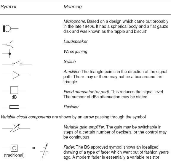
Table 8.1 Some symbols used in diagrams
There are two PPMs in the mixer shown. On small mixers there are often options: they can be chosen to operate as level indicators for stereo – one for left and the other for right, or possibly one for the M signal and one indicating S. Sometimes it is useful to have one for the main output and the other showing the level of some other output or input.
Mixers of this kind are designed to be flexible so that they can readily be used in a wide variety of situations.
Questions
1. You are given the job of laying out microphone cables, via a fairly complicated route, from a studio area to where the mixer will be placed. At this time, neither the microphones nor the mixer have been provided. Which way will you have the cable?
a. With XLR sockets in the studio area and the plugs in the mixer area?
b. With the XLR plugs in the studio area and the sockets in the mixer area?
2. Which set of figures is correct about line-up tone?
a. Zero level, 100 Hz
b. +3 dB, 1 kHz
c. About 0.775 V, accurate 1 kHz
d. Accurate 0.775 V, about 1 kHz