In Chapter 3 I discussed the use of the JK optical printer in a fairly straightforward manner as a means to do simple rephotography, resizing of the image, speed changes, superimpositions, dissolves and traveling mattes. With the exception of the last bit, these effects are fairly easy to accomplish once you get the hang of the machine and, even though Jaakko appears to be retired, there are still enough JKs around and people capable of their upkeep that without too much trouble you, dear reader, ought to be able to locate one to rent or borrow, or perhaps even purchase. Should you buy an optical printer and desire to augment it, or should you wish to build yourself one from scratch (as Bill describes doing with Paul Sharits in the interview in Chapter 3 and as Peter Rose describes at the end of this chapter), there are resources out there on the web and through forums to guide you in your work. For the most part, I love my optical printer. Basically, my filmmaking is a little rough, a little grubby, with chance and mistakes embraced as a central part of my practice. As such, my cranky analog JK works great for me. I haven’t changed it one iota since I bought it and it does everything I need it to do very well. On rare occasions I have had an optical technique that required more specialized gear and in those cases I have usually managed to get myself onto an Oxberry animation stand with aerial image projection to accomplish those goals. This chapter moves in two directions at once. It will discuss the highly specialized optical printers developed for the major motion picture industry and their use by avant-garde filmmakers, the augmenting of existing JK and other optical printers to create specialized machines for individual artists and the DIY (Do-It-Yourself!) optical printers from the 1970s and today.
OPTICAL PRINTERS AND THE MAJOR MOTION PICTURE INDUSTRY
Before digital effects, all special effects in the movies were accomplished through a combination of in-camera/on-set effects with complicated sets and mattes and paintings on glass in front of the lens combined with post-production opti cal printing. Raymond Fielding’s The Techniques of Special Effects Cinematography is an excellent overview of the various machines and machinists involved in this practice. All the different fixes that were developed and perfected to achieve the filmmakers’ goals are truly inspiring. This is true of the early optical printers, many of which were designed in large part to accomplish a goal of a director who had very little idea of how they (and the people who built and operated them) worked to achieve the director’s “vision”.
The first mass-produced optical printer was the Acme-Dunn printer. Made for military applications during World War II, by Linwood Dunn and Cecil Love, this printer received a technical academy award in 1944 (Fielding, p. 128). Called the Acme printer for short this device shared the majority of the commercial market for printers with Oxberry printers made by the Richmark Camera Co. out of New Jersey. The BHP Corporation of Chicago and Pioneer-Trebes also contributed printers to the field (SMPTE, p.684). When I started my film career, it was possible to find JK optical printers and Oxberry animation stands and possibly their printers at most film schools. Animators in particular seemed to love the Oxberry Master animation stand for its motion-controlled platen and the ease of creating fades and dissolves. Since the conversion of special effects and animation from analog/silver-based technologies to digital, studios and film labs have literally been giving Oxberries away or, worse, scrapping them. In contrast to the tabletop JK, an Oxberry requires a significant commitment of space, extra tall ceilings for the Master animation stand and a large room for the multiple-projection head step printers.
Over the last ten years that I’ve taught at Emerson College, we have had many offers to donate Oxberries to the college and most have been refused. We currently have a disassembled unit in storage as we wrangle with our facilities managers, architects, administrators and other faculty to find space to commit to the unit. Of course the arguments for and against its incorporation into our facilities are impassioned and spring from sound pedagogical rationales in keeping with the ongoing battle between those who wish to continue to use film technology and those who wish to see its back. In contrast with a basic projector/camera set-up (which would be relatively easy to cobble together from spare parts with a decent amount of technical know-how) making a multi-projector motion-controlled optical printer would basically be like building the space shuttle from scratch. Not impossible, but there would be a lot of tech you’d need to reinvent.
One artist who made remarkable use of commercial optical printers is Pat O’Neill. It was seeing his films 7362 (1965–1967) and Water and Power (1989) that made me want to experiment with traveling mattes. Unlike my crazy antics, O’Neill’s work is clean. It is also shockingly beautiful. 7362 is the number of the Hi-contrast 16mm motion picture stock made by Kodak that is used in traveling mattes. The film features biomorphic and mechanical forms in strongly contrasting colors pulsing and whirling around the screen. It is a masterful homage to the capabilities of the optical printer, and the stock and method that it represents.
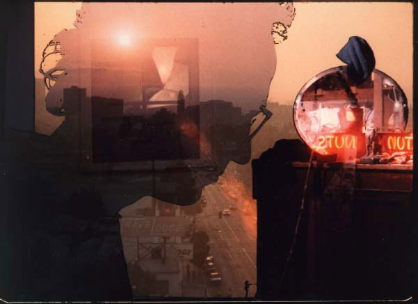
FIGURE 9.1
Still frame from Pat O’Neill’s Water and Power (1989). Courtesy of the artist.
Water and Power (see Figure 9.1) was shot in an office building in LA and the Owens Valley, and takes its name from the Los Angeles Department of Water and Power. The overlapping images in these spaces visualize the way in which the land is a palimpsest of all the natural and man-made efforts on it. Nature and culture course across the surface of the planet, leaving their traces and attempting to wash or work away that which has come before but the residue of processes is never entirely erased. With his stunning layers of superimposed images, O’Neill visualizes this perspective in a way that all the talking and writing in the world could never achieve. The film is breathtaking 35mm and has been preserved by the Academy of Motion Picture Arts and Sciences and added to the National Film Registry. O’Neill continues to live and work in the Los Angeles area and can be contacted via his website: www.lookoutmountainstudios.com/index.php.
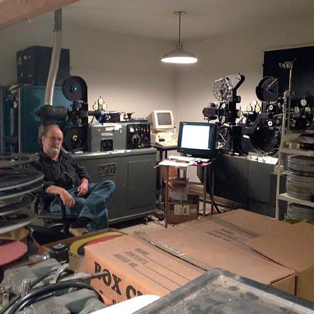
FIGURE 9.2
Pat O’Neill with his two optical printers. From an email communication with Mr O’Neill: “Both optical printers were made by Producers Service Co. in Burbank, California. Both were used in special effects houses, and bought second-hand by me. I don’t know any other filmmaker who used such equipment. The double-head printer, on the right, has not been used since 2000, and the other printer was converted to a scanner about five years ago.” Photo by Jennifer West, courtesy of Pat O’Neill.
There are few contemporary experimental and avant-garde artists who have the tools, the skills and the patience to do the kind of precision optical work that O’Neill did (see Figure 9.2). He was uniquely placed in time and space to become the artist he is. However, people continue to be very interested in optical printing. In the previous optical printing chapter, I wrote about traveling mattes and superimpositions and burned in titles, all of which I have accomplished on my little JK rather nicely and all of which you could do on a tabletop unit as well. The rest of this chapter is about building your own printer or modifying existing printers to suit your needs and there are four “case studies” of individuals who have done so. In every case, the tinkering was done in order to achieve a specific effect and usually progressed over the course of several films, if not entire careers to date.
BASIC DIY OPTICAL PRINTER
The basic components of an optical printer set-up is a projector and a camera that can advance a frame at a time (or can be modified to do so). I have seen home-made optical printers using Beaulieus, Filmos, Mitchells, Kodak Cine Specials and Arris with Super-8mm, 16mm or 35mm capabilities. Some, like Mitchells, are often made to work with either 16mm or 35mm film and simply require a gate change inside the camera. Almost always optical printers have a dedicated camera. In other words, once they are set up they stay set up and the reason for this is that the fine adjustments necessary to set up a camera perfectly aligned with a projected frame, or more frequently the actual backlight frame of film, are so tedious that, once completed, it is unlikely that the maker will want to disconnect everything to shoot. But it doesn’t have to be this way; it is just something to think about as you design your own system. To design your own system you will need:
• A film projector in the gauge of your choice with single-frame advance capacity and/or an inching knob. In 16mm that is something like a Kodak Analyst or Pageant that can single frame. Some of these even come with a corded remote or pedal to advance the film and they can run forward and reverse. If you are working with Super-8 there are Eumigs that have inching knobs and many of the old silent projectors in Regular-8 and 16mm formats have gate assemblies that can be removed as a single piece away from the shutter and lamp, and have inching knobs attached. Then you are left with the problem of finding a light source that is powerful, cool and easy to focus.
• A camera that can single frame in the gauge of your choice. Popular choices are reflex Bolexes, Beaulieus and Mitchells, the former two in Super-8mm or 16mm.
• A single-frame adapter or an animation motor so that you can advance the film without jiggling the camera.
In order to set up the camera to shoot the film you will need to do one of the following things:
• Have an optically clear mirror, ideally mounted in a black box with just the projected image coming in one side and the camera filming in from the other, which would look like Figure 9.3.
• OR using an extension tube or bellows extend your lens so that it can shoot an extreme close-up of the gate (see Julie Murray’s design below).
• OR (and this requires more space and a light-tight room) project your image onto a piece of frosted glass or glass with vellum on it and frame up your image on the other side. NOTE: unless the film that you are copying has sprockets on BOTH sides so that you can flip it right to left, your image will be backwards.
• OR (also requires a very dark room to work) put your camera right next to your projector, project onto a white surface and film. Carolee Schneemann did this in the credit sequence for Plumb Line (1968–1971) and it looks amazing.
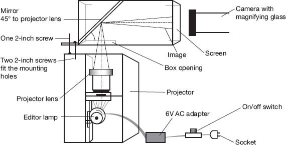
FIGURE 9.3
An illustration of a rudimentary optical printer set-up found as part of the description by Raul Lopez Herrera of his Super-8 to Super-8 system, www.city-net.com/~fodder/s8mm/optprint.html.
A system designed with just these pieces should be able to reproduce film frame for frame as well as create superimpositions, speed changes and even titling. Below is a home-made optical printer by Julie Murray. Julie is an Irish-born artist who lives and works in the United States. She makes work in a variety of mediums including drawing, painting, sculpture, film and video. In the early 2000s she built her own printer. Her description of her process as well as pictures are below.
JULIE MURRAY—BASIC DIY OPTICAL PRINTER
For the projection part of the unit, Julie used a Bell & Howell 16mm projector and she cut away the housing around the gate, removing the shutter and lens. She replaced the light source that came with the film projector with a slide projector that provided a cool (as in blue) and very bright light positioned directly behind the gate (see Figure 9.4). A Bolex with an extension tube and lens was positioned opposite the projector gate (much like a JK optical printer) so that it was framed and focused on the gate. The extension tube was sufficient to create the macro focus required. There was a slow motor attached to the inching knob so that the projection side of the device could be set up to “run” and the Bolex was mounted on a standard tripod (see Figure 9.5). Julie says that there was a significant amount of taping and shimming involved in setting up each session and her film If You Stand with Your Back to the Slowing of the Speed of Light in Water (2004) was filmed on this set-up.
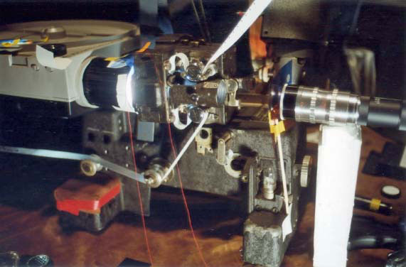
FIGURE 9.4
Close-up of the gate on Julie Murray’s printer. Notice that there is no lens on the printer and the camera lens has an extension tube on the back.
Julie mentions on her blog where she discusses making and working with this printer that she was inspired by Standish Lawder and a contact printer he made that filmmaker Mark Toscano posted on his blog (Toscano). Standish Lawder also made his own optical printer that he demonstrated when Robert Gardner interviewed him and Stanley Cavell on his show Screening Room (Gardner). Filmmakers inspire each other across the generations not just with their artwork but also with their techniques and tools.
After building and working with her own optical printer Murray acquired a JK that she continues to use to this day. Recently she sent me this picture. It is an iPod leaning against the gate area of a JK rig so that she can shoot titles for her film (Figure 9.6). Shooting with color 100ASA color neg, she framed up the image so that she could get about one inch of text. She inverted the image (so that it was white letters on black) and set the screen brightness to maximum. The results she says kind of had a Super-8 feel, a bit indistinct at the edges with some screen texture that she liked.
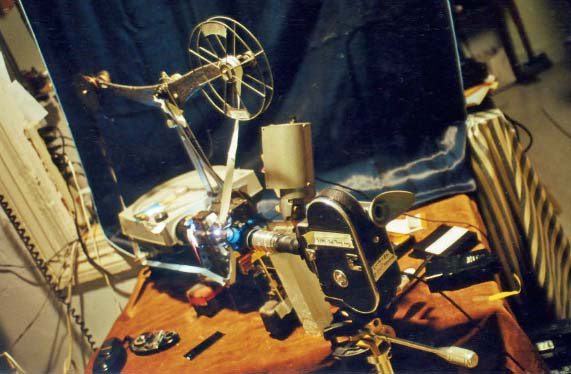
FIGURE 9.5
A shot of the whole set-up in which you are able to see the slide projector, take-up reel, camera on a tripod and the small table that it is all set up on.
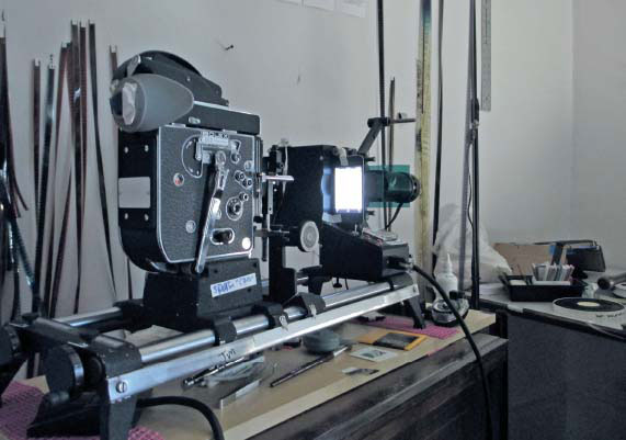
FIGURE 9.6
Julie’s JK/iPhone title stand. Courtesy of the artist.
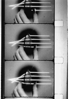
FIGURE 9.7
Film still of If You Stand with Your Back to the Slowing of the Speed of Light in Water (2004), Julie Murray. Courtesy of the artist.
KENNETH ZORAN CURWOOD—DIY OPTICAL PRINTER WITH AERIAL IMAGE PROJECTION
Sometimes, instead of a camera being pointed directly at the gate or projected image, there is a mirror involved, so as to bounce the image into a mirror and then onto a semi-opaque surface (like frosted glass or glass with a sheet of vellum over it). It can then be rephotographed or the filmmaker can rotoscope, drawing individual frames on paper or animation cels from live-action material. This was possible with the aerial image projection capability of some of the Oxberry animation stands. The system designed by Kenneth Zoran Curwood detailed below has rotoscope capability and it is worth incorporating into your design if you are thinking of doing hand-drawn animation.
The first time I ran into a home-made rotoscope device was in the mid-1990s. I was living in New York City and worked for a bit with filmmaker Jeff Scher as he was completing a bread commercial. In his studio I saw the first versions of home-made rotoscope devices. He had removed a gate, with an inching knob with the lens and feed and take-up spindles still attached, from an old 16mm projector and bolted it to the bottom of a coffee can that he had sawn a hole in to let light through. A goosenecked light was clamped above and you would maneuver it to shine enough (but not so much as to burn the film) onto the film frame. This whole thing was attached to some sort of a frame, perhaps an old enlarger, although I seem to remember a 2 × 4 piece of wood was involved as well. You could move the coffee can rig closer or farther from the table to change the size of your frames. Instead of projecting the image from underneath, this rig projected it down, which left your legs encumbered but sometimes your hands got in the way of what you were drawing.
I don’t know if that commercial was ever finished, but I remember I got a job offer to work on a feature for more money than I was making animating, so I bid Jeff adieu, but he continues to make some of the most breathtakingly beautiful rotoscoping I’ve ever seen. Incorporating watercolors, found objects, each frame different from the next, it is nothing short of stunning. In a brilliant marketing maneuver, once he has finished a film he puts the individual cels up for sale on his website, www.fezfilms.net. My first attempts at setting up a rotoscoping system in my home were inspired by his work. Interestingly, in the very small world that is the experimental film community, the person whose system I am describing next was also influenced by Jeff Scher.
Kenneth Zoran Curwood has made a very advanced optical printer with aerial image projection capabilities in both Super-8mm and 16mm. He details how the printer works in a video (Curwood). We also have this video on the companion website. The printer is built from pieces cobbled together from a variety of sources. There is a platen from a traditional animation table with Oxberry animation pegs. Like all animation tables, it has a cut-out area where a piece of glass is placed. Curwood has put a piece of vellum over it to create a screen that can be projected onto. The platen can also spin, move left and right (e/w) and up and down (n/s). There are also lamps to top-light animation on the platen should you wish to use it as a traditional animation stand and rephotograph paper cels.
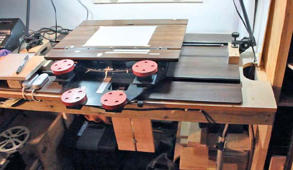
FIGURE 9.8
The platen of Curwood’s animation stand. I can tell from the peg bars that it was part of an Oxberry rig at some point. The red dials control the e/w and n/w movement of the peg bars (upper) and top part of the platen (lower). The circular black piece directly under the platen allows for moving the whole top part in a circle.
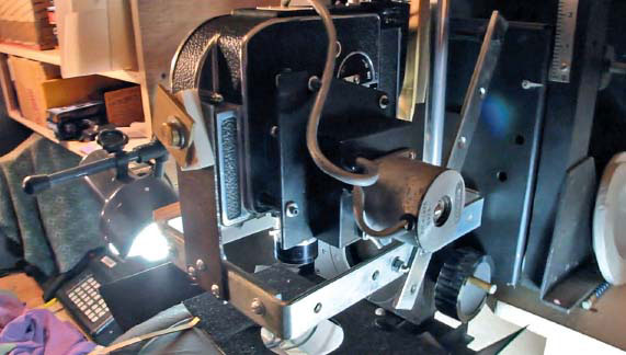
FIGURE 9.9
The Bolex has a motor attached that allows it to single frame.
The camera is a Bolex Rex 5. Curwood has designed an external shutter beneath the lens of the Bolex attached to a hood that goes around the lens and protects against reflections of the camera when the animation is top-lit. The external shutter can be used to create fades and other effects. The Bolex is controlled by an animation motor that can be controlled with a single-frame trigger from the tabletop and can also be hooked up to an Interval Time Sequence Motor (ITSM) built by Jaakko Kurhi. It is basically a time lapse motor but it allows for single framing.
The projectors slide into a shelf under the table and lay on their side so that the image is projected onto an optically clear mirror at a 45° angle to the projector and the table. This mirror bounces the image up, without artifacts or distortion. The camera is secured to a transom taken from a darkroom enlarger so that the camera can move up and down in relationship to the platen. This allows Curwood to change the size of the image. The whole set-up is relatively small and can fit in a large closet, which is both convenient, seeing as he lives in a city and space is at a premium, and remarkable, given all that it can do and how large a similarly capable Oxberry animation stand would be.
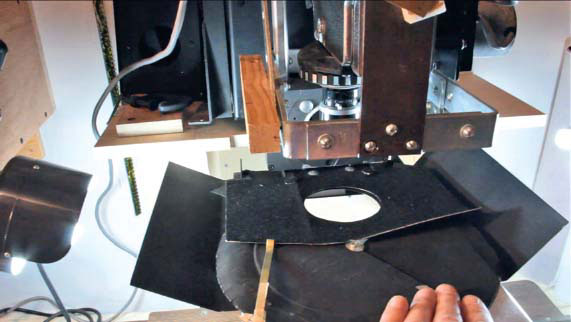
FIGURE 9.10
Beneath the Bolex is a shield to prevent light spill and reflection. Curwood has also built a shutter onto this to allow for certain special effects.
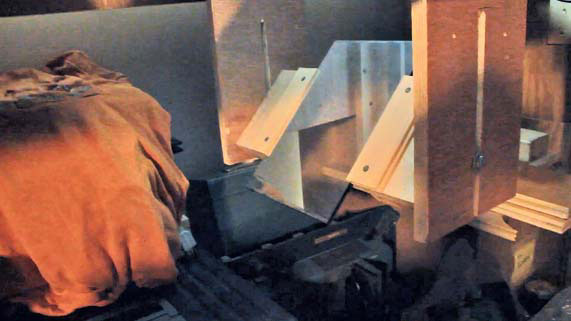
FIGURE 9.11
The mirror that bounces the image up to the projector.

FIGURE 9.12
The projector is capable of single-frame advance that can be operated via remote (not pictured).
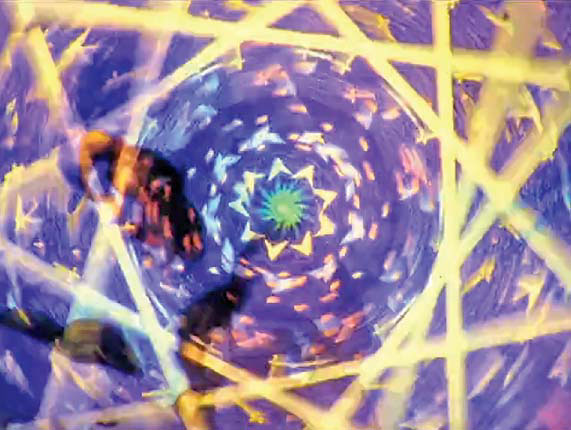
FIGURE 9.13
Film still from A Young Colossus by Kenneth Zoran Curwood. Inspired by the animations of the Whitney Brothers, this film has nine layers of superimpositions throughout. Courtesy of the artist.
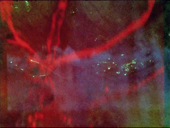
FIGURE 9.14
Still frame from Matt McWilliams’s optically printed 16mm film Produce.
MATT MCWILLIAMS—DIY OPTICAL PRINTER + OPEN-SOURCE CODE
Matt McWilliams was one of my BFA students at Emerson College several years back and we’ve kept in touch on and off over the years. A few years back he told me he was making an optical printer that interfaced with a computer and of course I asked if he would be willing to be included in this book. Matt is part of a loose network of moving-image and sound artists in the greater Boston area. He is also really interested in open-source code. This all ties into his willingness to share his plans for his printer, the code and the parts to manufacture the parts for the motor on a 3D printer. He has made the work available online and provided links to the code. I have also provided the code as PDFs throughout the instructions. What follows is a brief interview with him alongside these instructions as I find it impossible to extricate Matt’s motivations for making his own printer from his method of doing so. Enjoy!
INTERVIEW WITH MATT MCWILLIAMS + INSTRUCTIONS ON HOW TO MAKE A DIY OPTICAL PRINTER
Kathryn Ramey: What inspired you to make your own optical printer?
Matt McWilliams: I wanted to make an optical printer because I was disappointed by the limitations of the existing technologies for rephotographing 16mm. The JK line of printers are amazing machines, but their control systems employ dated interfaces that I thought could be updated. Rather than be limited to using a physical box that relies on an archaic programming language, I wanted to be able to use a desktop or tablet computer and software more like an audio sequencer to control the printer or even write scripts that could be stored, re-used and modified instantly rather than manually entered over and over.
I chose to modify existing projectors because I personally witnessed a lot of them being junked. When a motor or some other essential part of a projector dies people are often faced with a choice: throw it away or pay for an expensive restoration. It’s been my goal to provide another option for projectors facing the trash heap. I don’t really advocate cannibalizing working projectors, but if it’s done from a perspective of learning and creating rather than destruction I don’t see the harm.
The other issue with existing optical printers I wanted to address was cost. Professional systems are rather expensive and by making an open hardware printer I thought students or amateurs without a large budget for film could explore optical printing. The JK optical printers are proprietary and were designed by professional film technicians but a project started from scratch by an amateur engineer, I thought, could benefit from the collaborative design process that has built things like the RepRap project. [ Author’s note: RepRap is an open-source desktop 3D printer available online. “RepRap is humanity’s first general-purpose self-replicating manufacturing machine.” (http://reprap.org/)]
KR: Where did you source the instructions and parts? Specific URLs would be great.
MM: The electronics and the projector are the only parts I didn’t fabricate for this project. I started with a Bell & Howell 16mm projector that needed a new motor. I stripped it down to nothing except the film gate and the gears necessary to move film through it.
Figure 9.15 is a comparable model but mine had more metal in the case. The core of the mechanical parts that drive this printer is the Arduino platform, a hobbyist microcontroller board for robotics and automation (see Figure 9.16).
To control the motor that drives the projector I used a “shield” for the Arduino. Shields are extension boards that plug into the Arduino and add capabilities with no soldering or wiring required. This I sourced from Adafruit, a company with an education-based approach to selling hobbyist electronics. Figure 9.17 is an example of a motor shield.
The motor driving the projector is a standard 12V DC motor that I tore out of an old paper printer. I kept some other elements from the printer to grab and drive the projector’s belt and advance or reverse frames.
I used an IR emitter and receiver pair (www.sparkfun.com/products/241), and a small square of tinfoil to act as an optical encoder, which allows the printer to move exactly one frame at a time. A small custom-printed circuit board was made to handle this function but it is not a necessary part (see Figure 9.18).
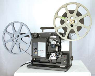
FIGURE 9.15
Old Bell & Howell 16mm projector.
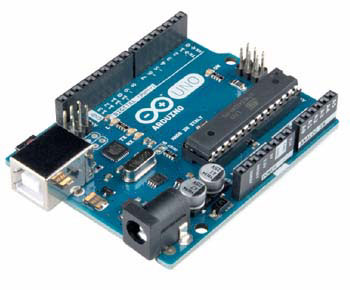
FIGURE 9.16
Arduino platform, a microcontroller board for robotics and animation.
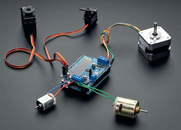
FIGURE 9.17
An Arduino shield board that plugs into the Arduino and adds capabilities without soldering or wiring.
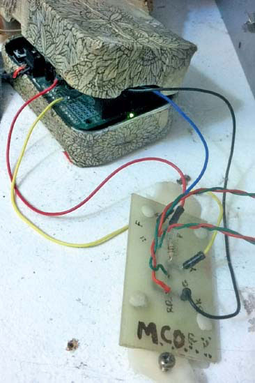
FIGURE 9.18
Small custom-printed circuit board.
Figure 9.19 (see end of chapter) is the Arduino code used to control the projector and can be accessed at: https://github.com/sixteenmillimeter/MCOPY_Firmware.
The optical printer uses a Bolex Rex 4 to rephotograph the film. Controlling the camera, originally, was a solenoid attached to a Bolex single-frame plunger. The solenoid was driven by another Arduino and a TIP120 transistor was used to handle the high voltage required. When attached to the same computer as the projector’s electronics, the camera and projector can be synchronized to act in concert.
Figure 9.20 is a still frame of a solenoid-based camera controller working alone and can be seen on video at: https://vimeo.com/38163365.
Figure 9.21 (see end of chapter) is the code to control the camera and can be accessed at: https://github.com/sixteenmillimeter/INTVAL.
The light source for the printer is a 50V MR-16 halogen bulb that is directed through the 25mm lens that came with the projector. The lens acts as a condenser, which hits a piece of diffusion that is positioned behind the film gate of the projector (see Figure 9.22).
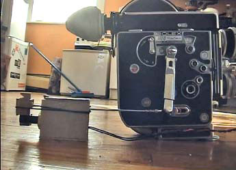
FIGURE 9.20
Still frame of the Bolex camera with single-frame motor.
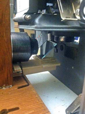
FIGURE 9.22
Light source for the optical printer made from a halogen bulb directed through a 25mm lens from the Bell & Howell projector.
For the sequencing software, the original interface was done in processing. It is a simple grid-based interface that allows the user to visually arrange instructions for the printer to do, in order. This is a metaphor that carries through all versions of the software.
It’s available from: https://github.com/sixteenmillimeter/mcopyFS (see also Figure 9.23 at the end of this chapter).
I wanted more flexibility so I re-wrote it in node.js, a popular web server technology that can be seen in Figure 9.27 (see end of chapter) or accessed at: https://github.com/sixteenmillimeter/mcopy.js.
This renewed approach allowed me to connect the camera and projector electronics into a desktop/server using USB, and to control the optical printer from a web page using any device on the same network. The mcopy.js source code is free, open source and extendable, and I hope it may appeal to others to do that or start a competing, higher-quality project.
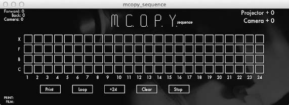
FIGURE 9.24
Grid-based interface that allows the user to visually arrange instructions for the printer to do.
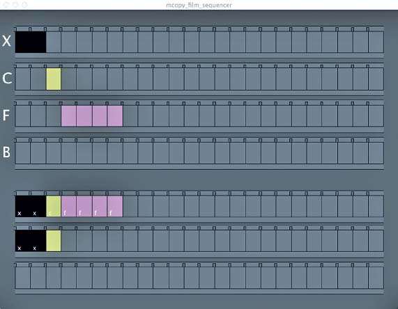
FIGURE 9.25
Grid-based interface that allows the user to visually arrange instructions for the printer to do.
The camera controller has already branched off into its own intervalometer project for Bolex 16mm cameras. The single-frame action originally used by the solenoid mechanism can be taxing on the Bolex spring motor over time, so I designed a side-mounted mechanism that uses the 1:1 shaft to advance and reverse the camera a single frame at a time while bypassing the motor completely.
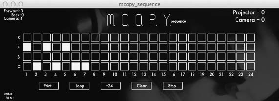
FIGURE 9.26
Grid-based interface for 18 to 24 step-up pattern.
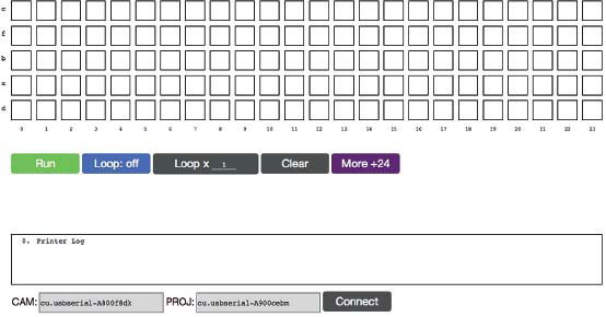
FIGURE 9.28
Desktop interface.
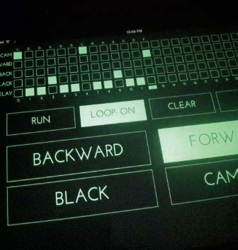
FIGURE 9.29
Tablet interface.
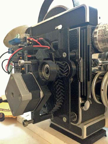
FIGURE 9.30
The time lapse motor connect to the Bolex.
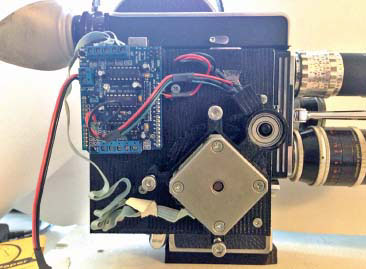
FIGURE 9.31
The time lapse motor connect to the Bolex.
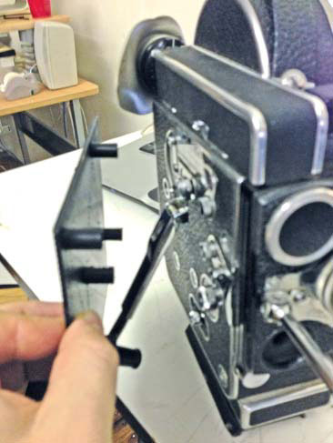
FIGURE 9.32
The cover of the interval motor as machined by the 3D printer.
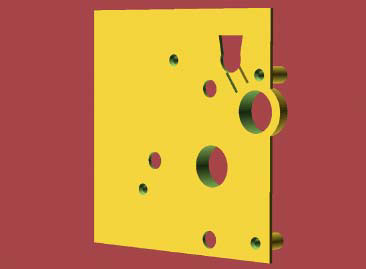
FIGURE 9.33
The render of the 3D piece before printing.
This was styled after the Tobin Time Lapse & Animation Motor. The motor the prototype uses is a 12V stepper motor that was also taken from a retired paper printer. The gears, boxes, supports and other parts of the motor were designed to be printed on a 3D printer. The motor can be seen in use in Figures 9.30 and 9.31 with examples of a 3D printed part in Figure 9.32 and the corresponding render in 9.33.
The entire project to date can be downloaded and 3D-printed from: www.thingiverse.com/thing:151944. The code repository for the entire project is represented in Figure 9.34 and is available online at: https://github.com/sixteenmillimeter/INTVALNext.
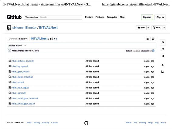
FIGURE 9.34
The code for the project.
KR: Are you a part of a community of filmmakers who you share your work with? How does this influence the kind and amount of work you make?
MM: There are two different communities I work with and for, which shape the way I approach filmmaking. One is a local group of Boston-area artists who show films in and around the city. Much of my work is extremely short form (2–3 minutes) and silent, so I seek out screenings that pair with musicians or experimental sound artists.
The other community I am a part of is the open-source, open-hardware community. I work on and participate with projects that I care about and that I use. I feel that film technology, particularly that relating to once-consumer-facing formats such as 16mm and Super-8, is a perfect candidate for the support of open-hardware creators. Movie film no longer has the corporate behemoths it once had catering to its needs and as a result many processes and technologies have been abandoned or neglected by the major advances in hobbyist electronics in the last few decades.
PETER ROSE—DIY + SUPER-COMPLICATED MATTE WORK
The final DIY optical printer guru is perhaps the most meaningful to me personally in this whole book. Peter Rose made the film The Man Who Could not See Far Enough (1986) and, when I saw it, I knew I wanted to be an experimental filmmaker. Years went by; I moved to New York City and then Philadelphia to pursue graduate school and through a strange twist of fate Jay Ruby, anthropologist and my mentor at Temple University, introduced me to Pete who then ended up hiring me as an adjunct teaching at the University of the Arts. Peter was and is brilliant and funny, and he was exceptionally generous with his knowledge and personal equipment. He let me use a homemade 100ft metal reel and tank he had made for hand-processing, and encouraged me to use the facilities at UArts that were in many ways superior to Temple for an experimental filmmaker. They had two Master Oxberries at that time and I shot a good deal of the animation and special effects for ENDLESS PRESENT: BIOGRAPHY OF AN UNKNOWN FILMMAKER, a film by Cornealius Thistle on those Oxberries. Eventually I also interviewed Peter for my dissertation and got to know much more about how he developed as an artist. There is an interview with him at the end of this chapter, but before that I want to go over his DIY optical printer and some of the work that he made with it, including the film The Man Who Could not See Far Enough.
PETER ROSE’S PRINTER—FROM AN EMAIL EXCHANGE WITH PETER
The printer had three elements. My father and I modified an old Kodak Analyst Projector so it could be triggered a frame at a time. An external motor and belt drove the frame advance and a small micro-switch signaled the motor to stop when the next frame came to rest. We removed the projector bulb and I mounted a slide projector and mirror outside the housing so the heat wouldn’t melt the film. A small fan with cardboard funnel was used to cool the film (see Figure 9.36). A photocell mounted in front of the lens sent a signal to the synchronizing device to tell the camera to shoot a frame.
The camera, a Beaulieu, was mounted on a lathe bed with vertical columns affixed so it could move in two dimensions. I taped a razor blade to the edge of the camera base and shone a flashlight down from above so the shadow of the razor blade fell on a piece of masking tape. Through trial and error I was able to make marks on the tape so that the resulting multiple images abutted each other nicely. Figures 9.35 and 9.39 show the set-up to some extent of Pete’s optical printer.
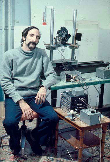
FIGURE 9.35
Peter Rose and his optical printer. Courtesy of the artist.
The camera had a complicated mechanism attached to the sync shaft: a small blade with a mirror attached would rotate once each frame. There was a photocell and a small lightbulb likewise attached and arranged so that when the shutter was closed the light would be reflected from the mirror onto the photocell and a signal would be sent to the synchronizing device to stop the camera motor. Unfortunately I don’t have close-ups of this.
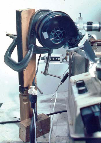
FIGURE 9.36
A small fan keeps the film cool. Courtesy of the artist.
The ensemble was controlled by the Synchronopticon—a hideously complicated affair of flipflops, capacitors, resistors, switches and wires that would count pulses from the projector and use these to trigger the camera. See Figure 9.38 for an image of the interior of this device. I could dial in any ratio:one camera frame per projector frame; every other frame; twice each frame; one extra frame every six projected frames; two skipped frames per three projected frames, etc.
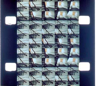
FIGURE 9.37
From the film Analogies by Peter Rose. Courtesy of the artist.
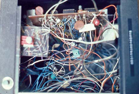
FIGURE 9.38
Interior of the Synchronopticon—the sequencer for Rose’s optical printer. Courtesy of the artist.
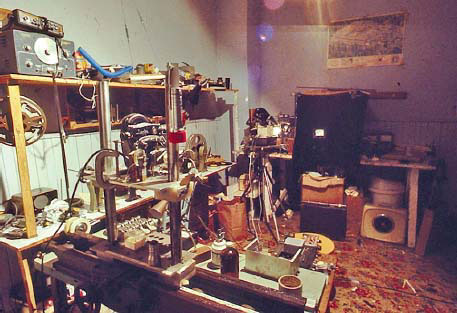
FIGURE 9.39
Rose’s optical printer took up an entire room. The camera sat several feet opposite the projector, which was covered with black cloth but for the projected image. This is partly how he was able to get such crisp and precisely registered results.
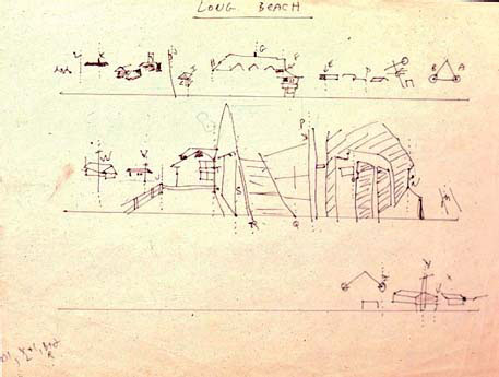
FIGURE 9.40
In order to achieve his elaborate motion effects The Man Who Could not See Far Enough it was necessary first to draw (visualize) the space of the effect (a scene from Long Beach seen here) and the camera movements for the different tracks (A–Z).
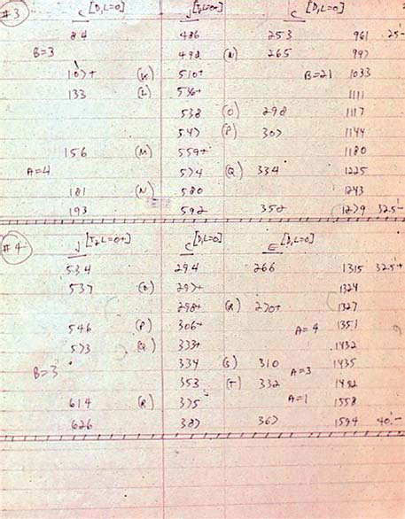
FIGURE 9.41
After shooting had been accomplished, the images needed to be rephotographed. In order to synchronize the images an elaborate camera plan was drawn up with specific frame counts for each strip of images. This is only one of several pages of notes.
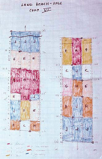
FIGURE 9.42
This information was also put onto a “map” so that Peter could determine where in the sequence shots began and ended.
Kathryn Ramey: So—a general question to get the grease flowing—do you consider yourself an artist, a filmmaker, a new media practitioner, a shaman, a performer? How do you describe who you are/what you do to your aunt or the old guy next door? Or children? Yourself? Your friends? Or do you even try?
Peter Rose: I find it very difficult to categorize what I do and usually try, without success, to avoid answering altogether. “Filmmaker” comes with all sorts of baggage—assumptions about mass audiences, scripting, collaboration, narrativity, economic positioning, etc.—that have no relevance to what I do. And “artist” comes with assumptions about galleries and another kind of positioning that are equally off the mark. “Avant-garde” is meaningless now. Likewise for “Experimental”, “Media Artist”, “Video Artist”, et al. It’s a problem and I have no pat answer here. An anecdote: I was once hitch-hiking through Greece and was picked up by an ancient Greek Orthodox priest and his younger acolyte. When I told them I was a filmmaker they asked what my films were like. I asked them if they had heard the sound of the goats’ bells coming from further down the mountain and if they were aware of the smell of the flowers by the road side. When they said “Yes” I paused … and said, “That’s my film.” I was thinking about some kind of conceptual synaesthesia but they seemed wonderfully satisfied with the answer. On a more personal, more interior level I suppose I see my process as akin to a kind of shamanic enterprise. I’m trying to wrest something transcendental from ordinary life, to “find some reprieve from the mercilessly forward movement of time and history”. (This last is from a whole bank of musings you’ll find at www.peterrosepicture.com/speech.php. I’ve put some of these below.) I explore the world around me—whether it’s the suspension bridges of NYC, solar eclipses off the coast of Africa, the tunnels under the expressway, the levels of a parking garage,1 or the inanities of the suburban landscape—and I try to transmute them into something mysterious and evocative.
KR: How did you come to your particular practice? Did you develop your own processes as a series of experiments? Where did the ideas come from? Does your form and method change as you go and, if so, where have you been and where are you going?
PR: I started out in mathematics, but I quickly concluded that I had no aptitude for truly creative thought in the field. At around the same time, this would be 1965, I attended a series of lectures given by Slavko Vorkapich at the Museum of Modern Art where I learned that film had a structural dimension and that very much intrigued me. My early work, drawing as well on my fascination with ideas of higher dimension found in science fiction, headed off into a direction that would now be called “structural”. I first tried superimposing multiple levels of imagery, in film, in the camera—and this led to Incantation. But there seemed to be limits to the process and so I sought a way to put twenty or so images into the same frame and this obliged me to design some kind of optical printer. My father, a highly esteemed and talented photographer and engineer working in the tradition of Muybridge, helped me to design an optical printer with which I was able to investigate what I called “diachronic motion” and that was where everything began. It was an immensely complicated, Rube Goldberg-like device that took us two years to design and I was very proud of it even if I had to hold my breath while using it for fear that somebody’s vacuum cleaner three apartments away would trigger extra frames. Much of my work is very low-tech. I take pride in inventing the necessary technologies, whether it’s a question of fashioning my own lenses to re-shape projected light or of inventing a new language. It goes back to Muybridge and the Lumière brothers, inventors all.2
KR: What role does media/technology/tools play in your work? What is the relationship between the media/tools and what your work is about? Is your work about something(s)?
PR: My ideas came first from questions about perception, time and cinematic structure, but those exfoliated into questions about language, light and space that were informed by readings in science, the sociology of language, philosophy and literature. Typically, certain unresolved issues in one work would lead to the next—some idea that was half-baked at one time would unfold into a new work within which there’d be the seeds for the next. I’ve always had a concern with the material/technical properties of media: the single-frame nature of film, the luminosity of video, the materiality of sound, the plasticity of digitalia. But I’ve also felt an obligation to embed this concern within a larger, more lyrical enterprise. So the work is, hopefully, about more than media-specificity. It is, by turns, comic, political, poetic, metaphysical. On the subject of agendas from a speech at the William Penn Foundation:
I think it’s always a bit foolish to talk about what I’m doing. You have to realize that I don’t really have an agenda, and that the pseudo-agendas I create for myself usually evaporate before the project is over. That is, the internal dialogues which I conduct with myself while making the work have no credibility for me two years later. They are simply scaffolds that I use to construct the work and which fold away after the project’s been launched.
That being said, I can affirm an interest in simultaneity, in paradox, in complexity; an interest in teaching an audience the rules of certain games and in exploring, with that audience, the implications of those rules. I’m interested in setting up these systems—visual, conceptual, linguistic—whose laws are known but which somehow get out of hand, that have unexpected implications—a life of their own—and that affirm, however metaphorically, the existence of something outside of a reductive materialism, that affirm the spirit.
I’m an escape artist. I aspire to travel in the fifth dimension, to speak unknown languages, to discover the next stage in the evolution of thought. I construct structural parables that allude to the possibility of there being more to the universe than our smug explanations permit. I try to subvert our tendency to deconstruct everything while, at the same time, self-deconstructing my own efforts. I throw a lot of words and ideas and images around and hope that some of them will stick together, and then I try to take credit for the consequences.
I think of myself as a poet—in the Maya Deren sense of the word—trying to find that vertical dimension to experience that serves as a reprieve from the mercilessly forward narrative movement of time and history.
KR: Where do you show your work? How do you want people to experience it? Is there a relationship between the form that your work takes and your desired venue/audience?
PR: My early work, in film, was shown at festivals, in museums, classrooms, etc. because that was the only way the work could be shown. There were a few distributors, but much of the thing was driven by word-of-mouth and the rare review. Canyon and the FMC were great, as were a few others who didn’t last as long. I often traveled with my work and that was quite rewarding. Video promised much easier distribution and exhibition (the quality of video sound was what initially drew me to the medium), but the scene was controlled by a handful of art curators whose tastes did not seem to extend to my work, so once again it was word-of-mouth. There were a few public broadcast stations that were open to experimental work and the festivals were, again, quite helpful, but it was a highly contingent process. The digital revolution changed a good bit of this. Until recently I had pretty much given up the idea of making anything off of my work and so decided to put much of it up on the web. (I’m about to sign with Fandor and will put up the film work there.) I put all my language work up at Ubu (www.ubu.com/film/rose.html) and a good bit of my other work is up at Vimeo and, to a lesser extent, at YouTube. I now find that, while the initial assumption was that one’s work would always be seen on a large screen, my working process, mediated as it is by my small 17″ monitor and given that it will be most accessible through the web, has led me to make work best seen, more intimately, on a similar kind of screen. So current exhibition and production media have definitely informed the nature of the work. Lately, too, I’ve made a number of video installation pieces3 and these oblige a very different sense of time. They tend to be very site-specific, too, so distribution is out of the question. But there is an engaging theatricality to installation that is quite attractive.
KR: And finally, your chapter is called “Optical Printing: DIY”. Please elaborate how you came to such an activity? Were you part of a community of makers (either locally or internationally) who communicate with each other about their work and got together either virtually or physically to discuss/show/celebrate? Where? When? How? What happened?
PR: And now for optical printing: many years ago there was an informal group of optical printerers and animation artists who would get together in NYC every so often to chat and to show each other work. Many of its members went on to make significant work: Sky David, Kathy Rose, Anita Thatcher, Paul Glabicki, and others. George Griffin was one amongst us and he put together a marvelous little book called Frames: A Selection of Drawings and Statements by Independent American Animators. It’s a wonderful embodiment of the kind of energy circulating in the group. Since then, of course, such acute attentiveness to structural possibilities has migrated to the digital realm and there are now countless communities of interest.
KR: How did your work with your home-made optical printer move into other kinds of work? Other kinds of tools?
PR: Since then my interest in home-built technology has led me to play with a tactic I call “transfalumination”. I found a way to project a sheet of light into space, rather than the usual linear beam, and have been exploring a method of drawing, or, more accurately, feeling with light. This is embodied in Studies in Transfalumination and in The Indeserian Tablets, both of which are on the web.4,5 Most recently I’ve been enthralled by the whole world of 3D video. I’ve been slowly researching the technology and aesthetics, which are actually remarkably alien. I’ve built my own rigs and have discovered spectacular ways of compositing the images so as to suggest a kind of six-dimensional vision. This is a natural elaboration of my initial interest in higher dimensions and in other structures of vision and it promises to be quite productive.
References
1. Odysseus in Ithaca, https://vimeo.com/6931757.
2. Analogies: Studies in the Movement of Time (excerpt), https://vimeo.com/48773161; Metalogue, https://vimeo.com/6992030.
3. Pneumenon, https://vimeo.com/4186420.
4. Studies in Transfalumination, https://vimeo.com/6992175.
5. The Indeserian Tablets, https://vimeo.com/user1592855/albums.
Your assignment from Peter Rose
1. Take a long straw—non-transparent.
2. Go outdoors on a sunny day.
3. Stand it upright on a busy piece of ground with a lot of leaf clutter.
4. Notice that when the straw is stationary you can’t easily see the straw’s shadow; but when you move it, the shadow is now clearly visible.
NOTE FROM PETER ROSE: What’s of interest is that usually the shadow gets so broken up by the terrain that you can’t easily spot it, but as soon as you move it your kinetic perception kicks in and it’s immediately visible. Something about complex parallel processing in the visual cortex….
Code for Matt McWilliam’s printer
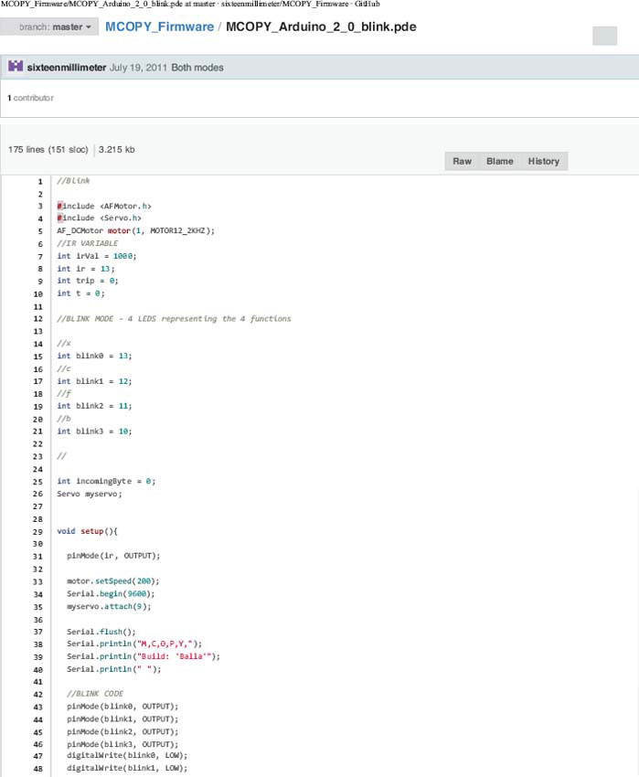
FIGURE 9.19 (1)
Arduino code used to control the projector. Also available at: https://github.com/sixteenmillimeter/MCOPY_Firmware.

FIGURE 9.19 (2)
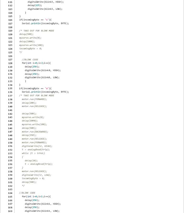
FIGURE 9.19 (3)
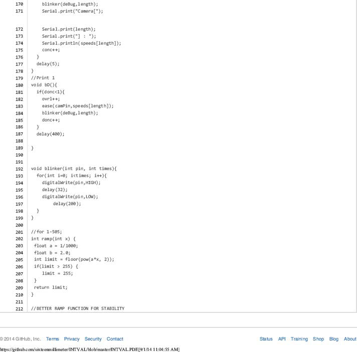
FIGURE 9.19 (4)
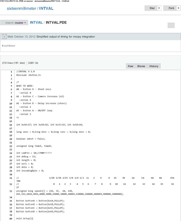
FIGURE 9.21 (1)
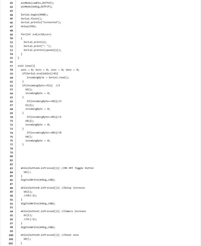
FIGURE 9.21 (2)
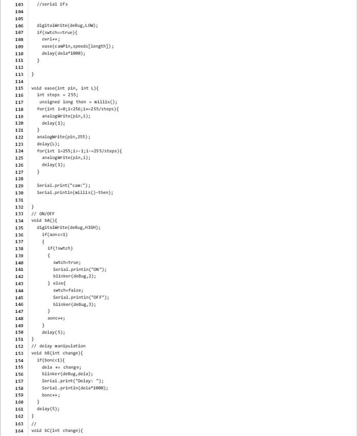
FIGURE 9.21 (3)
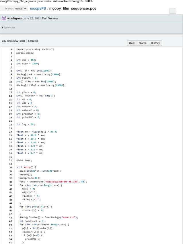
FIGURE 9.23 (1)
This is a simple grid-based interface that allows the user to visually arrange instructions for the printer to do, in order. Available at: https://github.com/sixteenmillimeter/mcopyFS.
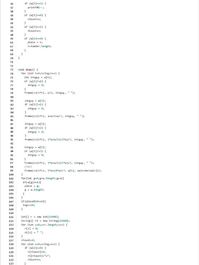
FIGURE 9.23 (2)
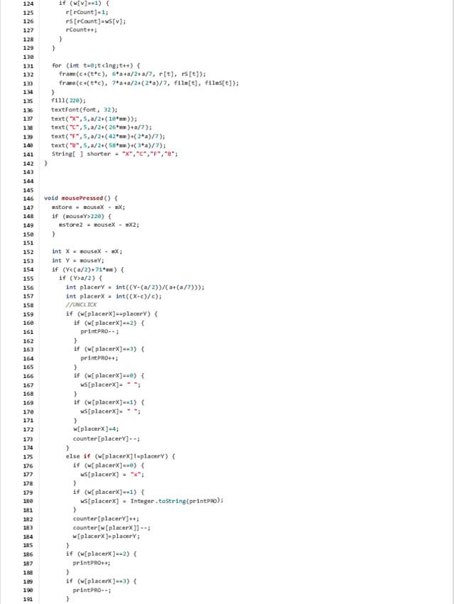
FIGURE 9.23 (3)
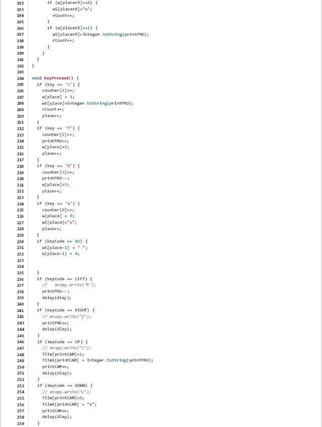
FIGURE 9.23 (4)
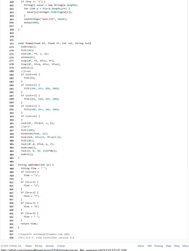
FIGURE 9.23 (5)
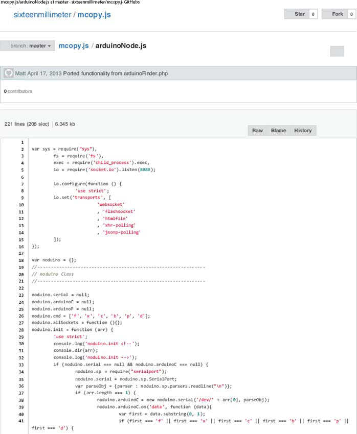
FIGURE 9.27 (1)

FIGURE 9.27 (2)
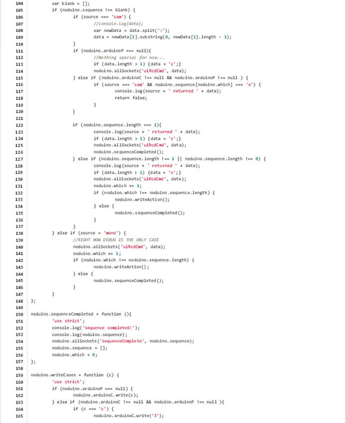
FIGURE 9.27 (3)
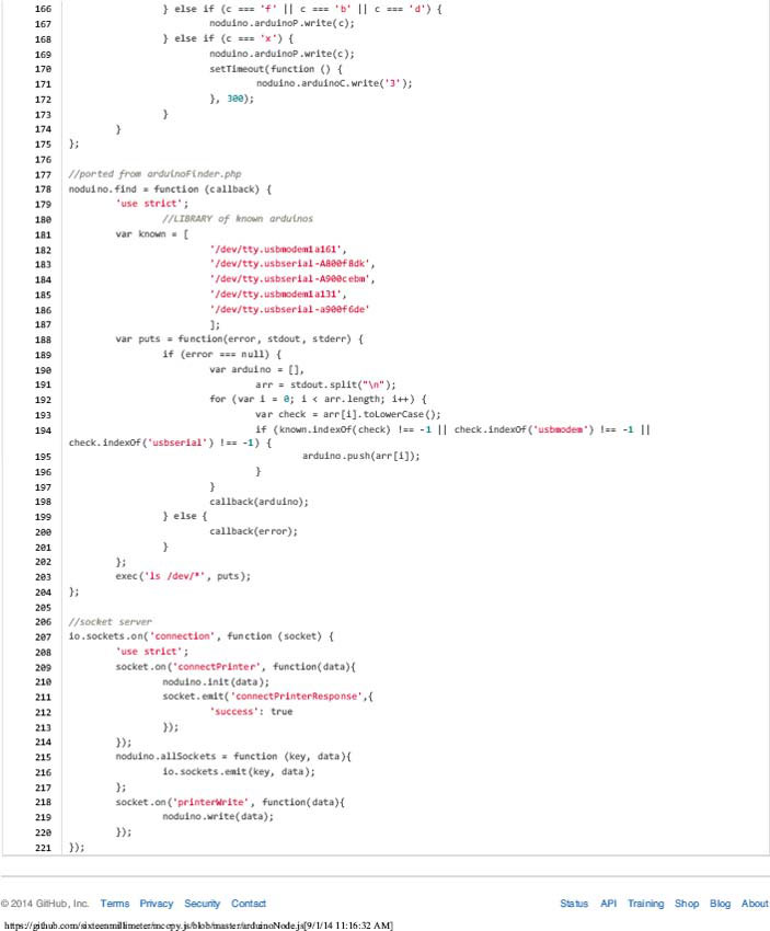
FIGURE 9.27 (4)
References
Fielding, Raymond. The Technique of Special Effects Cinematography. Boston, MA: Focal Press, 1985.
Gardner, Robert. 1973. Screening Room with Robert Gardner: Standish Lawder and Stanley Cavell. Distributed by Documentary Educational Resources, www.der.org.
“New Product & Developments,” SMPTE Journal, Vol. 88, No. 9 (September 1, 1979): 684–98. doi:10.5594/J16653.
Toscano, Mark. A contact printer. Wednesday, November 28, 2007. http://preservationinsanity.blogspot.co.uk/2007/11/contact-printer.html. Accessed January 29, 2015.