6
Laser-Based Bioprinting∗
Abstract
As one of the earliest technologies in patterning living cells, laser-based bioprinting (LBB) has been a powerful technique thanks to its high resolution and precision in bioprinting of high-cell density tissue constructs. Despite its great capabilities in fabrication of high-fidelity tissue constructs, LBB has little use in bioprinting domain compared to other bioprinting modalities due to its complex and costly laser-involved setup and a limited ability to generate heterocellular three-dimensional thick constructs. This chapter presents the evolution of LBB technology and describes its modalities in detail under two major groups including processes involving photopolymerization (stereolithography, dynamic optical projection stereolithography and two-photon polymerization) and processes based on cell transfer (laser-guidance direct writing, matrix-assisted pulsed-laser evaporation-direct write, and laser-induced forward transfer). Recent notable studies are highlighted, and relevant advances are examined. In addition, current limitations are discussed, and future prospects are presented to the reader.
Keywords
Dynamic optical projection stereolithography; Laser-based bioprinting; Laser-guidance direct writing; Laser-induced forward transfer; Matrix-assisted pulsed-laser evaporation direct write; Stereolithography; Two-photon polymerization
Great discoveries are made accidentally less often than the populace likes to think
Wilhelm Conrad Röntgen
6.1. Introduction
Stereolithography (SLA) is the first three-dimensional (3D) printing technology invented by Charles W. Hull and patented in 1985, where ultraviolet (UV) light selectively scans a photocurable material in a vat enabling selective solidification of the material layer by layer to create in 3D structures (Salonitis, 2014). SLA has been utilized in fabrication of tissue scaffolds; however, living cells were generally seeded postfabrication. The process brought various unique qualities to the fabricated scaffolds as SLA enabled construction of high-definition scaffolds with controlled geometry and interconnected porous architecture. Incorporation of living cells had not been attempted until 2004 when Boland and his coworkers at the Clemson University first attempted the use of a commercially available SLA system to bioprint human cells (Dhariwala et al., 2004), which was then further refined by various research groups as it enabled fabrication of highly complex scaffolds that cannot be achieved using droplet-based bioprinting (DBB) or extrusion-based bioprinting (EBB) modalities.
Transferring of living cells using a laser-assisted technology was first introduced by Odde and Renn (1999) to facilitate two-dimensional (2D) patterning of cells, which enabled rapidly formed patterns of viable cells on cover slides within cell media. Several other groups began to print living cells using laser energy from 2000 to 2010 including but not limited to Chickov's group in Germany (Ovsianikov et al., 2007a,b), Guillemot's group in France (Guillemot et al., 2010), and Chrisey's group in the United States (US) (Ringeisen et al., 2004). Although laser-guidance direct writing (LGDW) was first used for 2D patterning of cells, with the invention of laser-assisted bioprinting as an extension of matrix-assisted pulsed-laser evaporation (MAPLE), fabrication of 3D tissue constructs became feasible. All these approaches and techniques utilizing laser energy to pattern cells and fabricate 3D tissue constructs are classified under the technique, referred to as “laser-based bioprinting (LBB).”
Due to its high accuracy and resolution, LBB has been preferred in biofabrication of well-defined tissue constructs; however, its highly intricate setup limited its use in bioprinting domain compared to other commonly available bioprinting modalities, such as EBB or DBB. Although there is only one company in the world utilizing LBB for commercialization of tissues such as skin, there is currently no commercially available laser-assisted bioprinting technology that is applicable to direct cell printing (Roots Analysis Private Ltd, 2014). Researchers, however, can acquire components of the setup and custom build their own platforms. On the other hand, there are various companies commercializing SLA-based 3D printers, which can be modified for fabrication of cell-laden scaffolds. The use of toxic photoinitiators for rapid curing of tissue scaffolds limits the further transition of SLA and its modifications into the bioprinting arena.
With the advent of two-photon polymerization (2PP) and its application in the field of tissue engineering to the fabrication of tissue scaffolds with unprecedented resolution capabilities, and the invention of dynamic projection printing, which increases fabrication speed significantly, utilization of these technologies in the bioprinting has escalated in the last decade.
This chapter presents LBB with a thorough discussion on its modalities including the processes involving photopolymerization and the processes based on cell transfer. A detailed discussion is provided to the reader revealing the advantages and limitations of LBB with respect to other bioprinting modalities including EBB (Chapter 4) and DBB (Chapter 5), recent notable studies are highlighted, and the future prospects are presented to the reader.
6.2. Modalities of Laser-Based Bioprinting
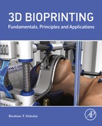
According to their working mechanisms, LBB techniques can be classified into two major submodalities including (1) processes involving photopolymerization and (2) processes based on cell transfer (see Fig. 6.1). Processes involving photopolymerization include SLA, dynamic optical projection stereolithography (DOPsL), and 2PP, and processes based on cell transfer can be further classified into three including LGDW, matrix-assisted pulsed laser evaporation-direct write (MAPLE-DW), and laser-induced forward transfer (LIFT).
6.2.1. Processes Involving Photopolymerization
6.2.1.1. Stereolithography
Photopolymerization-based bioprinting of tissue constructs is performed similar to typical SLA used in 3D printing of objects. In SLA process, as shown in Fig. 6.2A, the bioink solution (cells in a photocurable material) is loaded into a vat, which is equipped with a porous table mounted on an elevator apparatus that controls the position of the table in z-axis. For the first layer, the table is positioned to the surface of the bioink solution, which is then exposed to UV; to immediately polymerize the bioink. In photopolymerization, monomers or weakly crosslinked polymers, in either liquid or solid state, interact to form 3D polymeric network. Absorption of a photon by a photoinitiator leads to generation of radicals, which react with monomers and initiates radical polymerization (Ovsianikov and Chichkov, 2012). The photoreaction is terminated when two radicals react, which takes places in regions that are exposed to irradiation. The entire layer is scanned based on the toolpath obtained from the computer-aided design (CAD) model. When the solidification of a layer is completed, the porous table moves down to a distance equal to the layer thickness to print the next layer. The process continues in the same manner until the entire tissue construct is built.
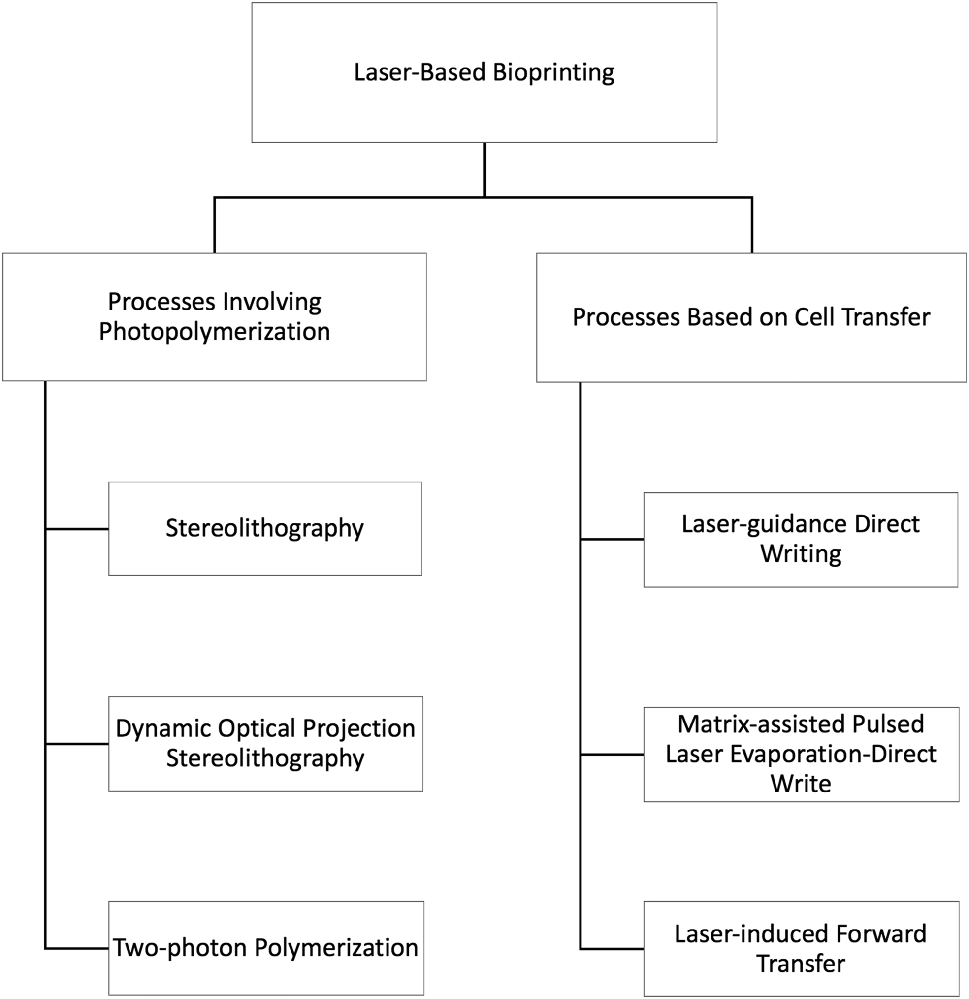

Figure 6.2 (A) A typical setup of stereolithography for bioprinting of tissue constructs. Sample 3D-printed tissue constructs including spatially controlled multimaterial bioactive poly(ethylene glycol)-dimethacrylate scaffolds in the form of (B1 and B2) multilumen conduits loaded with two fluorescent particles (Reproduced/adapted with permission from Arcaute et al. (2006)) and (C) a rook chess piece (Reproduced/adapted with permission from Arcaute et al. (2010)).
SLA allows bioprinting of tissue constructs ranging in size from a few hundred micrometers to a few millimeters (Bajaj et al., 2014). The application of SLA in bioprinting was first demonstrated by Dhariwala et al. (2004). Using a commercial SLA 3D printer (SLA-250, 3D Systems), they encapsulated Chinese hamster ovary (CHO) cells (cell line CHO-B2) within poly(ethylene oxide) (PEO) and poly(ethylene glycol)-dimethacrylate (PEGDMA) hydrogels to construct tubular geometries. In their study, over 90% cell viability was achieved and the authors showed that increasing the photoinitiator within the hydrogel solution decreased the cell viability in the second day. A similar approach was taken place at the University of Texas El Paso, where Arcaute et al. (2006) used the same 3D printer equipped with a He–Cd laser (325 nm, 40 mW) for encapsulation of 3T3 fibroblasts within PEGDMA hydrogels. They bioprinted cylindrical scaffolds with multiple channels, which could potentially be used in nerve conduit fabrication (see Fig. 6.2B1 and B2). Using a self-aligning minisetup, the same group further demonstrated fabrication of multimaterial scaffolds in highly intricate geometries (see Fig. 6.2C). Jeong et al. then used a similar approach in utilizing a commercial SLA printer and encapsulated 3T3 fibroblasts within microvascular stamps made of poly(ethylene glycol)-diacrylate (PEGDA) and PEGDMA hydrogels to mediate neovascularization within chorioallantoic membrane of chick embryos. The authors demonstrated that treating the printed samples with 12-O-tetradecanoylphorbol-13-acetate, which is a protein kinase C (PKC) activator, enabled cells to express multiple angiogenic factors, including vascular endothelial growth factor (VEGF) and endothelin-1, which in turn mediated the formation of neovessels within chorioallantoic membranes.
In SLA, the photocurable material determines the speed of curing and the resolution of the process. It should possess certain mechanical, biological, and chemical properties to serve for different tissue fabrication purposes. In this regard, the right combination of photocurable materials, curing agent, solvent, bioreagent, and light absorber should be selected to design the optimal process. There are a wide variety of photopolymers used in SLA such as acrylates with urethane units and most dialkylacrylamide (particularly trimethylolpropane triacrylate) (Lu and Chen, 2012). Along with photocurable hydrogels, photoinitiators have been used to speed up the solidification process as well as improve the mechanical stability of the tissue constructs as they have low photodissociation energy. However, photoinitiators are not easily applied to bioprinting as they are toxic and can harm the cells. For example, the least cytotoxic of known photoinitiators, Irgacure 2959 (2-hydroxy-1-[4-(2-hydroxyethoxy)pheny]-2-methyl-1-propanone) is cytotoxic at the concentrations greater than 0.5% (Melchels et al., 2010), where only 25% of the cells were viable after a day in an aqueous PEGDMA resin. Other studies recommend a concentration of <0.1% for Irgacure 2959 (Lu and Chen, 2012; Fedorovich et al., 2009); however, using such low concentration can result in low mechanical properties and hence excessive swelling as well as increased depth of curing, which affects the solidification in other layers and deteriorated the quality of bioprinting.
6.2.1.2. Dynamic Optical Projection Stereolithography
Dynamical optical projection SLA is a digital mask, or maskless, projection printing system that utilizes a digital micromirror device (DMD) available in conventional computer projectors (Hribar et al., 2014). In the literature, various research groups experimented with a dynamic mask system in microstereolithography (μSLA) to accelerate the fabrication process. For example, a liquid crystal display (LCD) was proposed as a dynamic mask for fabrication of double-end collector fluidic parts and springs (Bertsch et al., 2000). Later in 2005, Itoga et al. (2004) demonstrated the use of LCD projectors in μSLA, where micropatterning of PEGDA was achieved enabling attachment of endothelial cells (ECs). As LCD has a limited optical efficiency, Chen and his coworkers utilized the DMD approach as it offers better performance in terms of optical fill factors such as 85% with DMD versus 64% with LCD and light transmission with 71% in DMD and 21% in LCD (Lu and Chen, 2012). In their approach (see Fig. 6.3A), the general system operates as in traditional SLA system where a UV (365 nm) source can be used to polymerize photocurable materials. The digital mask, generated by a DMD device, enables controllable and interchangeable reflected light patterns rather than static, impractical, and more expensive physical masks used in photolithography process (Hribar et al., 2014). The DMD chip reflects the collimated UV light based on a digital pattern with a resolution of 1920 × 1080. The digital patterns were drawn in series of Microsoft PowerPoint images to generate a dynamic mask (Lu and Chen, 2012). The chip consists of an array of mirrors, which are coated with reflective aluminum and can tilt in two angles either +12 or −12 degrees with respect to the surface. By tilting the mirrors, “on” and “off” states can be obtained at +12 or −12 degrees, respectively, where the pixel appears dark while the illuminated light is reflected away from the projection lens. A motorized z-axis is used to enable fabrication of scaffolds in 3D using a typical layer-by-layer fabrication approach.
The major advantage of using DOPsL approach over other SLA-based bioprinting techniques is that DOPsL is rapid, as each layer can be made at once in seconds, which is a highly complex process using serial writing in single-photon polymerization (Billiet et al., 2012). It allows precise fabrication of scaffolds with complex internal architecture. However, the major limitation of the system compared to single/two-photon polymerization is the lack of high resolution due to the limitations of the projection lens. The other limitation of the system is the substantial use of photocurable materials (containing expensive biological reagents), which needs to be loaded in the vat resulting in loss during loading and unloading of the system. In addition, the thickness of each layer is difficult to control unless a light absorber is added to the bioink material. In this regard, the authors demonstrated the use of perfluorohexane (C6F14) as a support material, which is an inert liquid with high density (1.685 g/cm3) and a molecular polarity that is smaller than that of the photocurable material (Lu and Chen, 2012). To use the support material, the authors made a modification in the build platform. In this regard, an automated syringe pump system was used to fill the vat with the photocurable material and perfluorohexane independently. The vat was first filled with perfluorohexane leaving some space at the top of the vat for the photocurable material. Upon solidification of the photocurable material on the top of the vat with exposure to laser energy, the motorized z-stage was submerged into perfluorohexane to clean the uncured material. Next, the stage was elevated to print the second layer. The cycle was repeated until the entire scaffold is built. The authors also tested the effect of oxygen deprivation as oxygen is a strong radical inhibitor and could be detrimental to polymerization at low initiator concentration. In this regard, a nitrogen environment was employed, which increased the gelation speed and hence the bioprinting speed; however, leakage in the system caused some fluctuations in curing process.
Using DOPsL approach, Chen and his coworkers have bioprinted various cell-laden scaffolds. Fig. 6.3B1 and B2 illustrates a bioprinted vascular network to demonstrate cancer cell migration into the printed channels (Huang et al., 2014). High-definition vascular channels were created using PEGDA hydrogel-laded HeLa cells and noncancerous 10 T1/2 fibroblasts. It was shown that HeLa cells migrated significantly when the vascular channel diameter was decreased. Recently, they demonstrated the use of human pluripotent stem cell–derived hepatic progenitor cells (iPSC-HPCs) encapsulated with other supporting cells such as human umbilical vein endothelial cells (HUVECs) and adipose-derived stem cells in two layers of gelatin methacrylate (GelMA) (Ma et al., 2016). Such work demonstrated the bioprinting of a human liver model mimicking anatomical complexity of liver microenvironment. In addition, they bioprinted hexagonal structures with encapsulated in green fluorescent protein–labeled HUVECs demonstrating proliferation of HUVECs over time (see Fig. 6.3C1–C3) (Gauvin et al., 2012).

Figure 6.3 (A) The schematic of dynamic optical projection stereolithography (DOPsL) system, where digital masks are generated to control the status of micromirrors (on/off) to direct the UV light selectively onto a photocurable material; bioprinted tissue constructs using DOPsL system including (B1) a vasculature in multiscale on poly(ethylene glycol)-diacrylate (B2) with high-definition capillary structures (scale bar = 100 μm) (Reproduced/adapted with permission from Hribar et al. (2014)) and (C1–C3) hexagonal scaffolds with spreading of green fluorescent protein–labeled human umbilical vein endothelial cellshuman umbilical vein endothelial cells on day 1, 2, and 4 (scale bar = 100 μm) (Reproduced/adapted with permission from Gauvin et al. (2012)).
6.2.1.3. Two-Photon Polymerization
SLA has a high resolution in lateral plane (x–y axes) and is widely used in fabrication of microscale objects; however, its depth profile resolution is inferior. The resolution of SLA depends on the focal spot size and is limited by diffraction resulting in a minimum feature size equal to half of the applied laser wavelength; however, due to technicalities inherent to SLA technology, the best lateral resolution obtained so far is in the range of a few microns (Gittard and Narayan, 2010). Therefore, with the advent of 2PP where two photons are exerted on the same point simultaneously confining the region of polymerization in 3D (Fig. 6.4A), resolution has been increased significantly (Cumpston et al., 1999). In 2PP, the structural resolution beyond the diffraction limit (the limit on collimating a laser beam) has been realized bringing the feature size to less than 50 nm, which is an order of magnitude smaller than the laser wavelength (Emons et al., 2012). In single-photon polymerization, a fluorophore is excited by a single photon of a specific energy level, whereas multiple photos are used to excite the fluorophore with a relatively lower level of energy in multiphoton polymerization (Bajaj et al., 2014). The probability of two-photon absorption is proportional to the square of the laser intensity, which requires simultaneous absorbance of multiple photons (Zipfel et al., 2003). While femtosecond pulsed lasers are capable of very high peak intensities at moderate average laser power, they are suitable for and widely used in 2PP (Ovsianikov and Chichkov, 2012). Use of 2PP is limited in the bioprinting domain as the resolution achieved is far greater than the average size of mammalian cells; however, the technique has been applied in tissue engineering for fabrication of high-resolution scaffolds. Early efforts in use of multiphoton process for biological hydrogels demonstrated spatial patterning of bioactive materials into existing photoactive materials in 3D (Hahn et al., 2006). A precursor solution of low molecular weight PEGDA or acrylate-PEG-peptide containing a photoinitiator was allowed to diffuse into the PEGDA hydrogel, and a multiphoton photopolymerization approach with a digital mask was utilized to solidify the biologically active materials within PEGDA hydrogel. The authors also demonstrated migration of HT-1080 cells within acrylate–PEG–RGDS-patterned sections within the entire construct. In addition to the abovementioned hydrogel, a limited number of materials have been used in 2PP including commercially available ORMOCOMP® and SU8, which support cell growth and proliferation as well as facilitate formation of cell–cell junctions (Ovsianikov and Chichkov, 2012). Using these commercial materials, Serbin et al. (2004) fabricated porous tissue scaffolds, 3D pulmonary alveoli-like structures (see Fig. 6.4B1 and B2), and hollow microneedles for transdermal drug delivery (Ovsianikov et al., 2007a,b). One of the greatest advantages of this system is that it operates at room temperature, preventing the denaturation of proteins or biologically active materials. In addition, the system does not require costly clean room facilities. As this technique couples high-definition technology with the nanoscale resolution, it may be beneficial in a hybrid bioprinting platform, where small nanosize features can be built to control adhesion and orientation in 3D. For example, Fig. 6.4C1 and C2 shows multiscale constructs printed using a two-step 2PP process made of protein-repellant PEGDA as the frame and protein-binding Ormocomp cubes to support cell adhesion. Such environment facilitated control on 3D culture of cells with engineered adhesion points. Ovsianikov et al. (2014) recently demonstrated the use of 2PP in bioprinting of living cells. They used water-soluble photoinitiators (two benzylidene cycloketone-based photoinitiators G2CK and P2CK), loaded human osteosarcoma MG63 cells in 20% methacrylamide-modified gelatin (gelMOD), and printed Yin-Yang symbols successfully. The results demonstrated that a significant cell damage was observed due to reactive species generated during 2PP, and only 25.7% of the cells were viable in the voids of Ying-Yang constructs (see Fig. 6.4D1). Interestingly, 95% of the cells were viable outside the laser-exposed regions and cells trapped within the voids of Ying-Yang constructs proliferated in 3-week in vitro culture (see Fig. 6.4D2).

Figure 6.4 (A) A schematic of two-photon polymerization (2PP) process for cell encapsulation (bottom image), (Reproduced/adapted from Ovsianikov et al. (2014)). Fabrication of 3D pulmonary alveoli-like structures made of SU8: (B1) a computer-aided design model and (B2) a SEM image (Reproduced/adapted with permission from Ovsianikov et al. (2007a,b)). (C1) Two-step 2PP of scaffolds with protein repellant poly(ethylene glycol)-diacrylate (as the frame) and protein binding Ormocomp cubes (red) and (C2) 3D reconstruction of confocal images showing cell adhesion on different Ormocomp cubes at different heights and stretching of f-actin filaments (Reproduced/adapted with permission from Klein et al. (2011)). Bioprinting of MG63 cells in 20% methacrylamide-modified gelatin, (D1) where 2PP was used to generate Yin-Yang symbols (in dark red) demonstrating live (green) and dead (red) cells. (D2) MG63 cells trapped within the voids of the 2PP hydrogel construct proliferated in 3 weeks (Reproduced/adapted from Ovsianikov et al. (2014)).
6.2.2. Processes Based on Cell Transfer
In LBB processes based on cell transfer, cells are bioprinted by utilizing the mechanism of transferring living cells from one location to another in either culture medium or viscoelastic hydrogels such as alginate and Matrigel™.
6.2.2.1. Laser-Guidance Direct Writing
LGDW is the first LBB technique used for bioprinting of living cells. It was first demonstrated by Odde and Renn (1999), where living cells were patterned in 2D using laser-induced optical forces. Based on the principle explained by Ashkin and Dziedzic (1987), who pioneered optical force–based particle manipulation, Odde and Renn (1999) used laser-beam focus and successfully manipulated thousands of particles simultaneously. Before attempting deposition of living cells, the authors demonstrated patterning of a wide range of organic and inorganic particles in both gas and liquid phases (Renn et al., 1999). The key parameter that determines the interaction between light and cells is the refractive index of the cells relative to the surrounding fluid, where larger differences promote further interactions. In their work, the authors called the technique “laser-guided direct writing” as there was no guidance, such as a mask, during the bioprinting process. In that study, as shown in Fig. 6.5, cells were loaded into the medium and the laser beam was weakly focused. When a cell interacted with the light, it generated a gradient force, which immediately pulled the cell to the center of the light (where the light intensity was maximal) and then pushed the cell axially in the direction of beam and deposited it onto the substrate of interest such as a coverslip. The authors demonstrated bioprinting of embryonic chick spinal cord cells at a velocity of 11.4 μm/s, where a force of 1 pN was exerted on cells (Odde and Renn, 2000). After bioprinting, cells exhibited normal proliferation and spreading characteristics confirming that they were unaffected by the applied laser irradiation. In their study, the authors demonstrated 2D patterning by changing the position of the low numerical aperture focusing lens, which was translated using a micromanipulator to move the focal point to a new spot adjacent to the previous location. Either single cells or cell clusters were printable with an average deposition rate of 2.5 cells/min. This number is quite low compared to what is achieved using current LBB technologies such as LIFT. One of the major limitations in this simple setup was the limited distance when the cells were transferred, which was about 300 μm as the beam divergence and connective fluid flow forces overwhelmed the optical forces (Odde and Renn, 2000). To better guide deposition of cells and achieve longer travel distance of cells in the centimeter range, the authors utilized a hollow optical fiber, which transmitted the light as well as passed the cells through the fiber core. The cells were transferred with a mean velocity of 53 μm/s through fibers with 100 μm inner diameter.

Figure 6.5 A schematic of laser-guidance direct write process, where cells are entrapped due to the gradient forces generated by the laser pulse and propelled toward a coverslip. The low numerical aperture lens is attached to a three-axis micromanipulator to print cells sequentially and create patterns. As the distance of cell delivery is limited to 300 μm, a fused silica hollow optical fiber is used to guide the laser beam and cells, which is elevated on a glass coverslip spacer with its long axis aligned coaxially with the laser beam axis and the focal point.
6.2.2.2. Matrix-Assisted Pulsed-Laser Evaporation-Direct Write
MAPLE was developed at the US Naval Research Laboratory in late 1990s to deposit fine layers of functional materials, including but not limited to organic compounds, chemoselective polymers, and biomaterials (Chrisey et al., 2003). Compared to conventional pulsed laser deposition, MAPLE enables deposition of wide range of organic and polymeric compounds from smaller to larger molecular weight with less damage resulting from the conversion from condensed to vapor state (Piqué, 2011). In MAPLE (see Fig. 6.6A), the organic compound is dissolved in a matrix, which is usually a solvent such as alcohol. The solution is then frozen at around −196°C forming a laser target (Fitz-Gerald et al., 2000). When the laser pulse strikes to the target, the photon energy absorbed by the matrix is converted to thermal energy, which is absorbed by the organic molecules within the solvent. These molecules are converted into a gaseous state with increased kinetic energy, resulting in desorption of the compounds from the matrix and selective transfer to the collector based on a user-defined pattern. As a result, a thin film is formed on the collector while the volatile solvent molecules with limited adhesion coefficients are pumped away in the vacuum chamber. MAPLE process enables transfer of compounds in their native chemical structure and biological functionality without denaturation. In the literature, it has been shown that the temperature of the matrix material influenced the morphology and other film characteristics (Sellinger et al., 2008). MAPLE technology, as is, could not be used for bioprinting of living cells as cells cannot be encapsulated within the matrix due to solvent toxicity. In addition, the incompatible nature of the cryogenic setup, heated substrate, and vacuum chamber is not a hospitable environment for living cells. For bioprinting, the setup was further modified to accommodate living cells. Cells are first encapsulated into bioink solution, and a thin coating is formed under a ribbon. Thus, the technology was further adapted and evolved into a viable form for bioprinting of living cells.

Figure 6.6 (A) A schematic of matrix-assisted pulsed-laser evaporation process. Phase-contrast images of bioprinted cells using matrix-assisted pulsed laser evaporation direct write: (B1) human dermal fibroblasts showing normal morphology at 4 h, (B2) bovine pulmonary artery endothelial cells approximately 1 min postbioprinting, (B3) rat neural stem cells approximately 1 min postbioprinting, and (B4) mouse myoblast cells 20 h postbioprinting (Reproduced with permission from Schiele et al. (2009)).
MAPLE-DW process utilizes all benefits of MAPLE, where a thin layer of biomaterial (i.e., hydrogels) is coated at the bottom side of a transparent quartz support (print ribbon). The purpose of the quartz material is to absorb the wavelength of the laser. In general, the majority of the laser energy is absorbed by the ribbon as well as the biomaterial–ribbon interface. This reduces the severity of genetic damage caused by the UV light. In this regard, Corr's group conducted DNA damage analysis to determine whether gelatin-based writing induces double-strand DNA breaks (Schiele et al., 2010). In their study, the bioprinted fibroblasts were positive for Hoechst nuclear staining without any colocalization with phosphor-H2AX, indicating that the process did not induce any double-stranded DNA damage to fibroblasts. In MAPLE-DW, a range of laser fluences below the ablation threshold of the coated material is used (Zhang et al., 2015). When the laser beam passes through the support material, it focuses at the interface of the quartz support and the coated material (the sublime part of the coated material), which results in rapid localized heating followed by high-pressure vapor formation, generating a plasma bubble. The resulting bubble expands and ejects the coating material and transfers it to the collector substrate. The formation of the plasma bubble and hence the subsequent jet formation can be tuned by selecting the proper coating material based on its rheological properties as well as thickness and laser fluence. There are only a few hydrogels used as a coating material in LBB, such as alginate (Xiong et al., 2015a), Matrigel™ (Ringeisen et al., 2004), and gelatin (Schiele et al., 2010). Depending on the bioink properties, the laser pulse forms a thin or thick jet, which then breaks into one or more droplets and recoils back to the coating. A typical MAPLE-DW setup utilizes a low-powered UV pulsed laser, where a laser pulse with a short duration around 8 ns is applied to create bubble, transferring the jet from the coating material to the substrate (Riggs et al., 2011). In general, a short distance around 200–7000 μm is appropriate for successful patterning of living cells (Patz et al., 2006). Fig. 6.6B1–B4 shows bioprinting and patterning of various cells types transferred from a ribbon coated in a triazene dynamic release layer or Matrigel™ (Schiele et al., 2009).
6.2.2.3. Laser-Induced Forward Transfer
LIFT is an advanced version of MAPLE-DW, where cells encapsulated in a coating material on an optically transparent quartz support are transferred to a substrate in close proximity or in contact with the coating material. In LIFT, compared to MAPLE-DW, an energy-absorbing IR-transparent interlayer of thin film (in the order of 10–50 nm) of metal (Ag, Ti, Au), metal oxide (TiO2), or photo-decomposing volatile polymer (triazene) is used (Devillard et al., 2013). With the aid of the intermediate light-absorbing layer, the detrimental effects of intensive UV light could be sufficiently mitigated, which has increased the use of this technique and diminished the use of MAPLE-DW. A laser-induced setup consists of four major components including CAD software, a laser setup, a cartridge, and a substrate (see Fig. 6.7A), where the cartridge design is highly crucial to bioprint cells successfully.
The cartridge consists of three major layers including a supporting transparent quartz that holds the entire cartridge in place. Then, an interlayer thin film, generally gold, is coated on the bottom of the support quartz. Then, a thin layer of bioink solution is coated on the bottom of the gold layer. Techniques such as spin coating or coating with the aid of a blade can be used to generate a uniform layer of bioink material. The quality of the coating is crucial as it can easily influence the layer thickness, which can generate variations in the droplet size. Therefore, the coating needs to be carefully handled, and its viscoelastic properties should be maintained for reproducibility of the LIFT process (Devillard et al., 2013). During the bioprinting process, cells accumulate at the bottom of the bioink solution due to the gravity bringing inconsistencies to cell printing process. When the laser hits the transparent quartz support, the majority of it is absorbed by the intermediate layer, and the laser focuses on the region, where the absorbing layer and the coating intersect, generating thermal increase, which in turn generates a vapor bubble. The vapor bubble expands as the energy accumulates and a jet forms, which then transfers the bioink onto the substrate. In LIFT, there are three possible regimes. In the first regime (subthreshold regime) where the laser intensity is not sufficient, an annular shape is observed, or “coffee-ring” effect, as a result of droplet evaporation on a surface (Guillemot et al., 2010). When the bioink parameters including the laser fluence and the laser pulse energy are altered, the jetting regime can be obtained with proper jet formation. As the laser energy increases significantly, bubble bursting is observed. Concurrently, traces of film detachment become apparent, particularly around the laser spot (Guillemot et al., 2010). Fig. 6.7B represents a detailed schematic of bubble dynamics and jet formation during the LIFT process (Unger et al., 2011). First, the nanosecond laser pulse generates a rapid local vaporization of the region between the intermediate layer and the subliminal region of the bioink solution. As the vapor starts to expand, it can only expand in the direction of the substrate as the quartz support blocks the expansion of the bubble toward it. As the adhesion forces between the bioink and the intermediate layer prevent the bubble from detaching from the intermediate layer, the bubble maintains a temporary contact angle of 90 degrees (Unger et al., 2011). The contact angle further increases and the bubble expands in the direction of the substrate until the pressure of the vapor equalizes to the atmospheric pressure. Further expansion of the bubble results in decrease in the vapor pressure; however, the forward moving tip continues to flow due to the inertia, or the momentum gained. With the conversion of the kinetic energy of the vapor to the flow inside the bioink coating, the moving tip pulls the entire protrusion toward the substrate and the vapor bubble collapses. Jet formation begins with a thin tip continuing to elongate until breaking into droplets. As described by the Rayleigh principle (outlined in Chapter 5), droplet formation starts when the perimeter of the jet is larger than the perturbation wavelength.

Figure 6.7 (A) A schematic of laser-induced forward transfer system, which consists of a laser system (a laser source, an attenuator, a mask, a mirror, and an objective lens), a ribbon (quartz support, intermediate layer, bioink coating), image acquisition system (a charged couple device camera, a strobe light, a computer, and a delay generator), and the substrate, where the process parameters influencing bioprinting of cells are highlighted. (B) A step-by-step schematic of physical interactions during bubble and jet formation.
Unger et al. (2011) performed time-resolved imaging of hydrogel transport without the use of a substrate to understand the dynamics of jet formation. In their study, two different laser fluences were used including 1.6 J/cm2 (Fig. 6.8A) and 2.7 J/cm2 (Fig. 6.8B). After 2 μs of laser exposure, a protrusion started to form, elongating further in 5 μs. After 7 μs, the jet began to form and the protrusion diminished in 10 μs. After 20 μs, a bulge at the top of the jet formed due to collision of the hydrogel flow around the ablation spot and the vapor bubble collapsed (Unger et al., 2011). The jet then thinned significantly in 330 μs and broke into droplets; the sublime part of the jet then sprang back. At a larger fluence level (2.7 J/cm2), the jet formation process demonstrated some differences (see Fig. 6.8B). For example, at the beginning of the protrusion formation, the size of the protrusion was larger and longer at the early phase of jet formation. The diameter of the jet was greater than that formed under lower laser fluence. At 20 μs, a bulge formed at the sublime part of the jet and the bulge gradually diminished into a regular conic shape. The jet profile displayed fluctuations through the lapse time, where the jet thinned from 20 to 50 μs but it then thickened in 330 μs. After 670 μs, the jet broke into a single droplet as the volume of the jet was considerable larger than that under lower laser fluence. In 690 μs, the protrusion disappeared and the process was completed. Compared to the lower fluence at 1.6 J/cm2, higher laser fluence at 2.7 J/cm2 generated a thicker jet with a higher velocity and longer process (Unger et al., 2011).

Figure 6.8 Time-resolved images of jet formation during laser-induced forward transfer process under a laser fluence of (A) 1.6 J/cm2 and (B) 2.7 J/cm2 (Reproduced/adapted with permission from Unger et al. (2011)).
6.2.2.3.1. Droplet Impingement Onto the Substrate
Although LIFT utilizes laser technology, it generates droplets to be deposited onto a substrate similar to DBB techniques presented in Chapter 5. Therefore, impingement of droplets onto the substrate is crucial as it influences the bioprinting accuracy and manufacturability of 3D constructs. For hydrogels used in LBB, there are three main droplet impingement characteristics, such as splashing, spreading, and rebounding. In splashing, the droplet disintegrates into secondary droplets after colliding with a substrate; in spreading, the droplet expands its surface area; and in rebounding, droplets can rebound off the surface. Rebounding is, however, suppressed when viscoelastic hydrogels (i.e., alginate) are used owing to their high elongation viscosity (Bergeron et al., 2000). According to Weber, the critical number (We) of droplet splashing or spreading represented as:
![]() (6.1)
(6.1)
where ρ is the density of the liquid, d is the characteristics length which corresponds to the diameter of the droplet, U is the velocity, and σ is the surface tension. In general, larger Weber numbers result in splashes and lower ones lead to spreading. While these properties are important for the droplet formation, substrate properties on the collector (i.e., wettability of the surface, surface roughness, and viscous forces) are also critical (Roisman et al., 2002). Zhang et al. (2016) recently performed a study on impingement of alginate droplets using LBB. In their study, the authors showed that the critical Weber number obtained for 2%, 4%, 6%, and 8% alginate solutions are 2993, 3331, 5102, and 13,657, respectively. The corresponding laser influences for these critical Weber numbers are 1300, 1700, 1900, and 2500 mJ/cm2, respectively. By further understanding droplet impingement into a CaCl2 pool toward larger-scale tissue fabrication, the group later demonstrated bioprinting of 3T3 fibroblasts (loaded in 2% sodium alginate) into CaCl2 pool, resulting in a Y-shaped vascular constructs with a wall thickness greater than a millimeter (see Fig. 6.9) (Xiong et al., 2015a).
In sum, LBB processes involving photopolymerization and based on cell transfer have different advantages and disadvantages with respect to each other. Table 6.1 summarizes LBB techniques and compares their capabilities and features including their laser spot size, operating conditions, smallest printable feature that can be attained, cell viability, bioink printability along with their strengths and limitations.

Figure 6.9 Bioprinting of 3D thick tissue constructs fabricated using laser-influenced forward transfer. Y-shaped cellular tubes were printed with 2% sodium alginate loaded with 5 × 10⁶ cells/mL, where blue and green shows living cells performed using Hoechst and fluorescein diacetate assays, respectively (Reproduced with permission from Xiong et al. (2015a)).
6.3. Toward Multimaterial Bioprinting
The majority LBB techniques rely on single bioink material as it is difficult to fabricate multimaterial tissue constructs. As there is only a single bioink type utilized, making heterocellular patterns is thus a challenging task. The vast majority of native tissues are heterocellular with multiple cell types organized in a highly complex pattern (Ozbolat, 2015); therefore, it is vital for future LBB technologies to overcome this problem. In this regard, two major approaches have been proposed, one in SLA and the other in LIFT technology.
For SLA, Wicker's group developed a rotating vat carousel system on a commercial 3D Systems 250/50 SLA machine, which enabled circulation of different materials on a rotational stage (Choi et al., 2011). This way, multiple materials were incorporated into a single object. As discussed before, the authors also demonstrated a similar technology in 2010, where hydrogel-based multimaterial tissue scaffolds were fabricated using PEGDMA or PEGDA as the main biomaterial along with fluorescently labeled dextran (Arcaute et al., 2010). In their study, a minivat setup was developed that allowed removal and rinsing of the printed scaffolds, and loading and unloading of a new photocurable material. Similar attempts have also been made in mask-image-projection-based SLA, where a prototype setup was developed with a rotational system consisting of two materials, two brushes, a cleaner, and a dryer (Zhou et al., 2013); however, transition of such a technology into biomedical applications has yet to be investigated.
Table 6.1
Comparison of Laser-Based Bioprinting Processes
| Laser Bioprinting Modality | Laser Spot Size (Diameter) | Operating Conditions | Smallest Printable Feature | Cell Viability | Bioink Printability | Strengths | Limitations | ||
| Processes involving photopolymerization | Stereolithography | 75–250 μm (Arcaute et al., 2006, 2010) | ≤350 mJ/cm2 of laser fluence and (Dhariwala et al., 2004; Arcaute et al., 2006), λ = 325–365 nm (Arcaute et al., 2006; Dhariwala et al., 2004) | 250 μm features (Arcaute et al., 2006) | 87% (Arcaute et al., 2006) | 16.67% (w/v) polyethylene oxide (PEO) (Dhariwala et al., 2004), 20–30% (w/v) poly(ethylene glycol) dimethacrylate (PEGDMA) (Arcaute et al., 2006, 2010), 20% (w/v) (PEGDA) (Arcaute et al., 2010) | Intermediate fabrication times, patterned constructs with high mechanical strength | Low resolution, limited bioink material or material types, photoinitiator cytotoxicity at higher concentrations | |
| Dynamic optical projection stereolithography | N/A | 50 mW/cm2 of laser (UV) intensity (Gauvin et al., 2012) | Around 50 μm (Hribar et al., 2014) | 65–76% (Ma et al., 2016) | 10–15% (w/v) gelatin methacrylate (Gauvin et al., 2012), 20% (w/v) PEGDA (Huang et al., 2014) | Shorter fabrication times | Limited bioink materials or material types, limited control on deposited layer thickness | ||
| Two-photon polymerization | N/A | 330 mW laser pulses (80 fs, f = 75 MHz, λ = 800 nm) (Ovsianikov et al., 2007a,b) | ≤100 nm features (Ovsianikov and Chichkov, 2012) | 25.7% in laser-exposed regions and 95% outside the laser-exposed regions (Ovsianikov et al., 2014) | Hybrid organic–inorganic polymers (Ormocers®) (Hadjizadeh and Doillon, 2010), MG63 cells loaded in 20% gelMOD (Ovsianikov et al., 2014) | Very high resolution | Limited biomaterial types, not suitable for cell encapsulation unless water-soluble photoinitiators used, low cell viability around laser-exposed regions | ||
| Table Continued | |||||||||

| Laser Bioprinting Modality | Laser Spot Size (Diameter) | Operating Conditions | Smallest Printable Feature | Cell Viability | Bioink Printability | Strengths | Limitations | ||
| Processes based on cell transfer | Laser-guidance direct writing | N/A | 200–300 mW of laser power (Renn et al., 1999; Xu et al., 2003; Nahmias et al., 2005), λ = 532–830 nm (Renn et al., 1999; Xu et al., 2003; Nahmias et al., 2005) | 10 μm features (Odde and Renn, 1999; Nahmias et al., 2005) | 90% (Nahmias et al., 2005) | Spinal cord cells in media (Odde and Renn, 2000) | High resolution, high cell viability owing to weakly focused laser beam | Limited cell types and biologics because of refractive index constraints, viscous bioink materials are not printable, 3D bioprinting is difficult owing to bioink viscosity constraints | |
| MAPLE-DW | 10–200 μm (Ringeisen et al., 2002; Doraiswamy et al., 2006, 2007; Xiong et al., 2015a) | 50–2000 mJ/cm2 of laser fluence (12–30 ns, f = 10 Hz, λ = 193 nm) (Lin et al., 2009a; Xiong et al., 2015b; Doraiswamy et al., 2007; Ringeisen et al., 2002) | 25–50 μm diameter droplets (Lin et al., 2009b; Ringeisen et al., 2002) | 50–90% (Gudapati et al., 2014; Lin et al., 2010, 2009a; Xiong et al., 2015a) | 8% (w/v) sodium alginate without cells and 2% (w/v) cell-laden alginate (NIH 3T3 cells of concentration 5 × 10⁶ cells/mL) (Gudapati et al., 2014; Xiong et al., 2015a) | Viscous bioink materials of various material types, diverse cell types and biologics, intermediate resolution, nozzle-free transfer of cells | Thermal-induced cell injury, longer fabrication times owing to manual ribbon preparation procedure, low cell viability at higher laser fluence because of focused laser beam, simultaneous deposition of multiple bioink materails is difficult, patterned constructs of low mechanical strength | ||
| Table Continued | |||||||||

| Laser Bioprinting Modality | Laser Spot Size (Diameter) | Operating Conditions | Smallest Printable Feature | Cell Viability | Bioink Printability | Strengths | Limitations | ||
| LIFT | BioLP | 100 μm (Barron et al., 2005a,b) | 25–400 mJ/cm2 of laser fluence (2.5 ns, f = 0.1–100 Hz, λ = 248 nm) (Barron et al., 2004, 2005a,b) | 25 μm diameter droplets (Barron et al., 2005a,b) | 95–100% (Barron et al., 2005a,b, 2004) | 1–20 × 107 cells/mL in cell culture media (Barron et al., 2005a,b, 2004) | Minimum-side effects of the laser exposure due to the intermediate energy absorbing layer, viscous bioink materials of various material types, diverse cell types and biologics, intermediate resolution, nozzle-free transfer of cells | Longer fabrication times owing to manual ribbon preparation procedure, low cell viability at higher laser fluence because of focused laser beam, simultaneous deposition of multiple bioink materials is difficult, patterned constructs of low mechanical strength | |
| LaBP | 40–45 μm (Gruene et al., 2011a,b; Koch et al., 2012) | 1000–4000 mJ/cm2 of laser fluence (8–10 ns, f = 20 Hz, λ = 1064 nm) (Gruene et al., 2011a,b; Koch et al., 2012) | N/A | ∼100% (Gruene et al., 2011a,b) | 1.33% (w/v) hyaluronic acid-fibrinogen (viscosity 120 mPa s) comprising adipose-derived stem cells of concentration 2 × 10⁶ cells/mL (Gruene et al., 2011a,b), 4% w/v alginate comprising keratinocytes of concentration 1.5 × 10⁶ cells/mL (Koch et al., 2012), 3% (w/v) collagen type I comprising NIH 3T3 fibroblasts of concentration 1.5 × 10⁶ cells/mL (Koch et al., 2012) | ||||
| AFA | 300 μm (Hopp et al., 2005) | 360 mJ/cm2 of laser fluence (30 ns, λ = 248 nm) which ejected droplets at an acceleration reaching 107 × g (Hopp et al., 2005) | N/A | 80–85% (Hopp et al., 2005) | 2–6 × 10⁶ cells/mL in cell culture media (Hopp et al., 2005) | ||||

For the LIFT technology, Guillemot et al. (2010) proposed a high-resolution positioning system, which could be placed below a carousel holder with a loading capacity of five different ribbons. During the process, ribbons can rotate on a carousel holder using a motorized system providing additional freedom of motion. This way, different ribbons with different bioink materials can be switched through the process on demand to generate heterocellular tissue constructs. Although the authors envisioned a practical approach, the proposed automated idea has yet to be implemented.
6.4. Comparison of Laser-Based Bioprinting With Other Bioprinting Modalities
LBB is a nozzle-free approach, which circumvents a number of limitations with other bioprinting modalities, which utilize nozzle-based systems such as EBB (Ozbolat and Hospodiuk, 2016) and most of the DBB techniques except acoustic-based bioprinting (Gudapati et al., 2016). First of all, this feature eliminates the issue of shear stress–induced cell injury and death. This is particularly important in DBB and EBB when the nozzle diameter is very small or the bioink is highly viscous. High viscosity is a major problem in DBB as the majority of existing bioink materials used in EBB cannot be used for DBB but can be used in LBB. In general, the bioink material in DBB can easily clog the nozzle or the line from reservoir to the nozzle in the tubing system. This necessitates cleaning of the nozzle tip, reloading of the bioink, and calibration of the bioprinting setup, which is a time-consuming endeavor and sometimes results in permanent failure of expensive nozzles or the cartridge head. Due to high shear stress and the mechanism of droplet formation, a very limited number of cells can be encapsulated in each droplet. LBB, on the other hand, allows for bioprinting of cells in higher numbers, as it does not suffer from the above limitations. This is particularly valuable in generating higher resolution patterns with high cell density, which cannot be achieved using EBB.
The other major advantage of LBB is its high resolution, which is higher than that of DBB and substantially greater than that of EBB (Ozbolat and Yu, 2013). The resolution of DBB depends on the droplet size, which is around 50 μm encapsulating one or two cells; however, with the LBB, one can go down to 10 μm in resolution with this nozzle-free approach. Even with the use of a 20 μm nozzle tip to bioprint living cells, DBB cannot control the precise positioning of cells due to the large nozzle outlet diameter, which dramatically limits control over the distance between deposited cells. Moreover, in DBB, the number of cells encapsulated in each droplet cannot be controlled, where in general one, zero to two cells are encapsulated based on a statistical probability and cannot be repeated a priori (Dababneh and Ozbolat, 2014). These small resolution ranges cannot even be achieved using EBB. The high resolution advantage of LBB enables better control on cell–cell interactions and high-definition patterning of cells.
The other major advantage of LBB, particularly LIFT and MAPLE-DW, is its noncontact nature similar to DBB. This brings great potential for clinical applications of in situ bioprinting of tissues in surgery rooms (i.e., skin reconstruction or cranio- or maxillofacial surgeries). Injuries or defects can be easily filled layer by layer simultaneously patterning cells within the defect without physical contact. This feature has been used by Guillemot and his coworkers (Keriquel et al., 2010) in bioprinting of nanohydroxyapatite (HA) particles into calvarial defects in mouse models. The noncontact nature of LBB processes alleviates other major issues observed in EBB such as collision between the printhead and the bioprinted constructs, or unexpected increase in clearance between the orifice and the receiving substrate.
In addition to these advantages, some modalities of LBB, such as LIFT and MAPLE-DW, can be also performed horizontally as opposed to DBB and EBB, which are performed vertically. For example, in a few studies, LIFT has been studied with donor substrate oriented vertically and the jet produced horizontally (Barron et al., 2005a,b). This allowed for more convenient imaging with the integration of stroboscopic system for side imaging capabilities and enabled practical analysis of jet formation and the underlying physics. A different orientation has been achieved with direct light processing (DLP)–based bioprinting, which performs bioprinting in a top-down approach. Although the top-down approach is more precise, eliminating shaking of the top surface of the photocurable material, no clear advantage of using top-down approach in DBB or EBB has been identified yet. Perhaps, it may enable fabrication of more intricate geometries which normally needs support material due to gravity but does not need it when bioprinted top-down.
6.5. Recent Achievements in Laser-Based Bioprinting
Although LBB has been around more than a decade, very limited work has been done compared to that of other bioprinting modalities including EBB and DBB. A few seminal works in the domain of LBB have emerged in recent years.
Catros et al. (2011) demonstrated layer-by-layer fabrication of electrospun polycaprolactone along with LIFT-based bioprinting of MG-63 osteosarcoma cells. In their procedure, MG-63 cells were deposited onto electrospun layer (100 μm in thickness) in sodium alginate; the process was repeated three times to get approximately 300-μm-thick tissue constructs implanted into calvarial defects. The cells were proliferated significantly within the bioprinted tissue constructs. Although, the implanted tissue constructs generated fibrous tissue with limited bone regeneration, the work represented the scale-up fabrication of laser-inkjet bioprinted constructs, overcoming one of the most important roadblocks in LIFT.
Gaebel et al. (2011) utilized the LIFT technique to pattern HUVECs and human mesenchymal stem cells in a geometrically defined pattern on polyester urethane urea (PEUU); the fabricated samples were transplanted to the infarcted zone of rat hearts after LAD ligation. Eight weeks posttransplantation, samples with LIFT-derived patterns showed increased vessel formation compared to randomly bioprinted cells and the resulted myocardium patch provided significant functional improvement. Beside primary cells, human cardiac–derived cardiomyocyte progenitor cells (hCMPCs) were also bioprinted in mesh pattern (Gaetani et al., 2012). Bioprinted hCMPCs demonstrated phenotypic properties of cardiac lineage with enhanced expression of early cardiac transcription factors Nkx2.5, Gata-4, and Mef-2c.
A recent work by Phamduy et al. (2015) demonstrated bioprinting of cancer cells, including metastatic breast cancer cells (MDA-MB-231) and nonmetastatic MCF-7 cells, onto ex vivo rat mesenteric tissues. The ex vivo tissue was rich in vascular networks as well as lymphatic vessels. In addition to cancer cells, fibroblasts were also printed as fibroblasts support the metastasis of cancer cells. In their study, it was shown that cancers cells were transferred onto ex vivo tissues successfully in viable form and the metastatic MDA-MB-231 cells proliferated significantly (Burks et al., 2016). Interestingly, bioprinted cancer cells promoted angiogenic sprouting of the vascular network as new capillaries formed compared to unprinted control tissue. The abovementioned work demonstrated bioprinting of cells onto ex vivo tissues, which has great potential for revealing the mechanisms of cancer progression and metastasis; however, it is difficult to bioprint on ex vivo tissues in 3D; very few cells types, such as cancer cells, have the ability to penetrate though the stromal tissue as well as invade into the circulation system. In situ bioprinting, on the other hand, can enhance rebuilding of damaged tissue by bioprinting of cells directly into the defect site. In this regard, Guillemot's group demonstrated a framework study (Keriquel et al., 2010), where nano-HA particles were bioprinted into critical size defects in mouse skulls. Although limited bone regeneration was achieved, this study demonstrated bioprinting using LBB on live animal models for the first time.
6.6. Limitations
LBB systems have high resolution and enable precise patterning of living cells, where cells can maintain registry within 5.6 ± 2.5 μm to the initial pattern in LIFT process (Schiele et al., 2010). This resolution, certainly, cannot be achieved by other bioprinting modalities making LIFT the technology of choice for bioprinting of microcellular features in organs and tissues, i.e., microvasculature. Despite the high resolution, LBB has a number of limitations. Processes involving photopolymerization suffer from prolonged fabrication times, interactions of cell components with laser light, costly setup, and the need for photo-crosslinkable bioink materials. Processes based on cell transfer face with several weaknesses such as laser shock-related thermal- and mechanical-induced cell deformation, gravitational and random settling of cells in the precursor solution, costly laser setup, and limitations in bioprinting in 3D.
SLA has a limitation with the density and uniformity of loaded cells. Due to limited hydrogels used and the cytotoxic nature of photoinitiators, in general, structurally simple and weak constructs (except PEGDA, which can yield rigid constructs) can be built. The elastic modulus of such constructs is typically lower than 1 kPa (Narayan, 2014), which is only applicable to soft tissue engineering. As it takes longer time to build scale-up constructs, which can harm the cells over long print times, the studies are limited to generation of simple geometries. Another limitation with SLA is the nonuniformity of cell distribution as cells are prone to settling within the vat solution due to the gravity. This results in accumulation of large cell numbers at the bottom of the vat and a low cell concentration at the top of the vat. This is particularly problematic when using low concentration hydrogels are necessary to sustain cell viability. In addition, SLA has other limitations; the minimum feature size that can be attained is limited to the laser beam width, which is about 250 μm (Bajaj et al., 2014). As discussed previously, the resolution of SLA depends on the size of the focal spot and the diffraction, and the minimum size cannot be smaller than the half of the laser wavelength. Although these parameters determine the feature size, the resolution also varies among various photocurable polymers as well. Due to the limitations inherent to this technology, the highest resolution that can be attained is on the order of a few micrometers. The resolution in z-axis is even more limited, a problem that has been alleviated by the use of 2PP technique; however, this technique has limited use in bioprinting as only demonstrated in a recent work (Ovsianikov et al., 2014). In this regard, Chichkov's group combined 2PP with LIFT process, where PEGDA was used to 3D print high-definition porous scaffolds made of overlapping rings. Upon fabrication of the scaffold, vascular smooth muscle-like cells (vSMCs) and ovine ECs were bioprinted by changing the donor slide during the process, where vSMCs and ECs were seeded inside and outside the hexagonal borderline in Fig. 6.10, respectively.
Figure 6.10 Scaffolds fabricated via two-photon polymerization were then seeded with vascular smooth muscle-like cells (vSMCs) and endothelial cells (ECs) using laser-induced forward transfer, (A) where vSMC and ECs were deposited inside and outside the hexagonal borderline within scaffolds. (B) A fluorescence image demonstrating the localization of two different cell types with (C) detailed high-resolution images around the borderline.
The effect of UV exposure to cells and photosensitive materials as well as toxic photoinitiators used in the bioink solutions are some of the other major limitations in processes involving photopolymerization. The free radicals generated by the photoinitiators can adversely react with the cell membrane, proteins, and DNA, curtailing use in abovementioned processes. For example, Bryant et al. (2000) investigated the in vitro toxicity of various photoinitiators on dermal fibroblasts and reported that Irgacure 2959 was the least toxic UV-sensitive photoinitiator and triethanolamine was the least toxic visible light-sensitive photoinitiator. A similar work later demonstrated the minimal effect of Irgacure 2959 photoinitiator over a broad range of mammalian cell types and species (Williams et al., 2005). In their work, the authors also reported that different cell types had different responses to the same concentration of the same photoinitiators and the cell lines with shorter cell cycle were prone to photoinitiator-induced cell death.
One of the major limitations of LIFT and MAPLE-DW in bioprinting of tissues is the need for a highly sophisticated setup as well as the obstacles associated with the bioprinting in the third dimension. The majority of LIFT and MAPLE-DW approaches performed in such a way that only 2D patterns have been created. There are only a limited number of studies showing scalable fabrication of tissue constructs using these techniques. For example, Huang and his coworkers developed a vat system within calcium chloride (CaCl2) pool (Xiong et al., 2015b), where deposited alginate droplets were immediately crosslinked upon contact with the pool followed by lowering the table with a distance equal to the layer thickness. Using this approach, vascular constructs were fabricated; however, such capability primarily depends on the crosslinking speed of hydrogels as alginate quickly gels to fabricate such constructs. Other major challenges are the limited speed of printing, reproducibility of similar droplet formation, scaling up from small droplets to a larger tissue construct. In addition, the crosslinking mechanism needs to be integrated within the bioprinting process efficiently. Without successful crosslinking of the ejected droplets, droplets spread easily resulting in insufficient structural integrity necessary for the formation of scale-up tissue constructs.
One of the major limitations of LBB is the incorporation of multiple materials into the bioprinted construct (Choi et al., 2011). The existing technologies both in processes involving photopolymerization and processes based on cell transfer (MAPLE-DW, LIFT-DW, and LGDW) are not amenable to the incorporation of multimaterial bioprinting capabilities. The proposed carousel system by Wicker's group enables rotation of vats of different bioink solutions for the fabrication of multimaterial objects (Choi et al., 2011); however, switching from one material to another is time-consuming and brings about other issues during the fabrication process such as lower resolution of the system. It is highly challenging to remove the scaffold from the built vat and completely replace the photocurable material in it. During the switch from one material to another, it is critical to remove the bioink residue as it contributes to errors in built resolution. Particularly, material contamination needs to be minimized when switching to a different vat as the material accumulating on the bottom and side of the scaffold needs to be removed before building a new layer. The two-step approach proposed by Zhou et al. (2013), where rough cleaning followed by final cleaning slows down the fabrication process. The carousel system in LIFT, on the other hand, does not require any clean-up process as the scaffold is not built within the original bioink solution.
The last, but most important, LBB lacks a wide range of compatible bioink materials. LIFT and MAPLE-DW approaches are limited to a few hydrogels only, and processes involving photopolymerization have a limited choice of compatible bioink materials that are photocurable. Hence, no study so far has demonstrated compatibility of bioink materials other than hydrogels. Particularly, cell aggregate–based bioink materials have not been validated using LBB technologies. This is due to the relatively large size of spheroids and their immobility within hydrogels compared to single cells, which are easily encapsulated during bioprinting.
6.7. Future Directions
For future directions, several advancements should be made to make LBB modalities robust and effective in achieving the ultimate goal of bioprinting functional tissue and organ constructs. In this regard, adaption of DLP into the bioprinting domain will be highly beneficial as it will enable bioprinting of scale-up tissue constructs in a short period of time; use of a single UV light beam that traces the entire region of interest for solidification for each layer is time-consuming. This is, in particular, detrimental to cell viability as cells are encapsulated in monomer solution for an extended period of time without exposure to oxygen. In addition, the use of photoinitiators can also contribute to low cell viability during prolonged fabrication times. Thus, shorter fabrication times (in the order of minutes) will be very beneficial to the bioprinting and tissue engineering process. As photo-crosslinking of each layer takes the same time due to rapid exposure of a thousand of micromirrors, the number of layers required can contribute to extended build time. The number of layers can be easily minimized when the right orientation direction is determined (Ahsan et al., 2015). This, however, may affect the other properties such as surface quality and mechanical properties.
Most of the laser-assisted bioprinting modalities such as MAPLE-DW and LIFT have been used in patterning of living cells in 2D with limited fabrication of 3D constructs. This is highly dependent upon the crosslinking and solidification properties of the bioink materials used in the process. Up to now, a very few bioink types have been used in these processes (Riggs et al., 2011). These hydrogels are mainly thermally crosslinking hydrogels, such as gelatin and Matrigel™, and ionically crosslinking hydrogels such as alginate. In particular, constructs are limited to extremely thin structures when thermally crosslinking hydrogels are used as it is difficult to control the thermal environment confining the scaffold built volume. When thermally controlled substrates are used, the first few layers are easily crosslinked; however, control of the temperature around upper layers is difficult to maintain. Therefore, further advances should be made to assure efficient solidification in 3D.
Since larger-scale tissue construct necessitates the incorporation of macroporosity to support nutrient and oxygen transport, LBB modalities, except processes involving photopolymerization, become a less favorable option as these modalities do not support the generation of porous architecture. In this regard, fugitive or temporary hydrogels can be incorporated into the bioprinting process. For example, when thermally crosslinkable hydrogels are printed, sodium alginate can be printed using a secondary ribbon as previously discussed before. The crosslinker of sodium alginate can be printed within the thermally crosslinkable hydrogel and can crosslink alginate when they contact. Then, a “decrosslinker” of alginate can be used to remove the temporarily printed alginate creating porosity within the 3D construct. Similar architecture can also be constructed using thermally crosslinking hydrogel as a sacrificial support material in a similar manner. For building in z-direction, a movable stage with linear motor can be utilized to control the position of the substrate. As jet and droplet formation dynamics change when the distance between the substrate and ribbon changes, the bioprinting space should be maintained throughout the process.
One of the major advancements needed in LBB is the expansion of the library of photocurable bioink materials as well as the currently available bioink materials used in LIFT. As it is clear that LGDW and MAPLE-DW processes are not currently used in bioprinting field as they were superseded by the LIFT technique, novel materials need to be designed that can achieve uniform spreading of the bioink solution on the ribbon surface and uniform distribution of cells within the bioink coating, possess high viscoelasticity that will prevent bouncing and splashing of the formed droplet and secondary droplet formation, exhibit rapid gelation capabilities enabling bioprinting of thick tissue constructs in the third dimension, and exhibit a high level of biocompatibility that will enable cells to grow and proliferate rapidly without inducing an immunogenic response.
Integrating multiple bioink printing capabilities will be highly beneficial in fabrication of high-definition tissue constructs with multiple cells patterned into a tissuelike unique anatomy. Although some efforts have been made in advancing multimaterial printing capabilities in photopolymerization processes, there is currently no work demonstrating the alternative bioprinting of multiple cell types using cell transfer technologies such as MAPLE-DW or LIFT. The proposed carousal system in LIFT (Guillemot et al., 2010) has not been implemented as manipulations in the position of ribbons during switching influences the bioprinting dynamics of the jet significantly and generates significant variations during the bioprinting process. Therefore, instead of changing the position of the ribbon in the carousal system, multiple ribbons supported by multiple mirror systems that break the main laser beam into a few beams in series will enable bioprinting of the multiple bioink materials in tandem. As this configuration will enable bioprinting of multiple bioink materials, a translational stage is needed to switch the position of the substrate in the lateral plane back and forth. Using this approach, multiple bioink materials can be incorporated into a single platform.
6.8. Summary
LBB has been a powerful method in patterning living cells due to its great resolution and precision, as well as accommodating high cellular density, none of which are possible using low-resolution EBB or DBB with lower cellular density per the deposited droplet size. In addition to LGDW-, LIFT-, and MAPLE-DW-based approaches, processes involving photopolymerization have been of interest to the bioprinting community due to the commercial availability and easy of modification of SLA-based 3D printers. Despite these advantages, LBB has been challenged with its highly complex and costly setup, operational impracticability, low speed, and limited ability in fabrication of scalable heterogeneous tissue constructs; however, with the recent advances and progress in the field, the technology will be more practical for fabrication of 3D tissue constructs for tissue engineering and regenerative medicine practices in the near future.
..................Content has been hidden....................
You can't read the all page of ebook, please click here login for view all page.