35
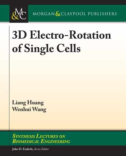
counterclockwise, as shown in Figure 2.15(a). When the phase shift is switched to 240°-120°-0°,
the electric eld rotation can be changed to clockwise, as shown in Figure 2.15(b).
(a)
(b)
Figure 2.15: Simulation of vertical rotational electric eld (about X-axis).
Overcome the cell sinking problem
Since the cell density is generally slightly greater than that of the solution, cells will sink to the
bottom. Once cells sink down to the bottom, they will adhere to the electrode surface, causing a
friction between cells and the bottom, aecting the rotation state. When the DEP torque acting
on the cells does not overcome the friction between the cells and the bottom, cell rotation can’t
be achieved. erefore, solving the problem of cell sinking is a prerequisite for ensuring a stable
rotation of cells in the vertical and horizontal directions. e electrodes could produce a vertically
upward DEP force by applying a signal with a phase shift of 180° (Vp-p = 10 V, f = 100 kHz) to
two thick electrodes and bottom electrode. Figure 2.16 shows the simulation result of the electric
eld distribution. ere is an electric eld gradient in the vertical direction, and the direction of
generated nDEP force is upward. When the sum of the DEP force and the buoyancy of the cell is
equal to gravity of the cell, it can prevent the cell from sinking:
F
DEP
+ F
bouyancy
= G. (2-1)
As the DEP force decreases with increasing distance in the vertical direction, there would
exist an equilibrium position for the cell in the vertical direction. e strength of DEP force can
be adjusted by changing the amplitude of the signal, which can regulate the equilibrium position
of the cells in the vertical direction.
2.3 THICKELECTRODE MULTIELECTRODE CHIP DESIGN
..................Content has been hidden....................
You can't read the all page of ebook, please click here login for view all page.