
36
2. THICK-ELECTRODE DEP FOR SINGLE-CELL 3D ROTATION
(µm)
7.21×10
5
×10
5
(µm)
140
120
100
80
60
40
20
0
3
2.5
2
1.5
1
0.5
-100 100-50 500
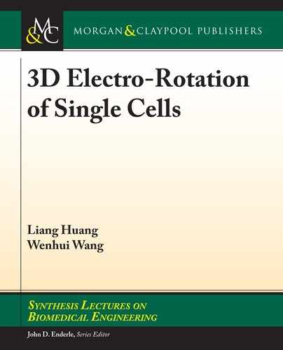
Surface: Electric Field (V/m) Arrow: Electric Field (V/m)
Figure 2.16: Simulation of cell suspension electric eld strength.
2.4 CHIP FABRICATION
e chip is composed of upper and lower layers. e upper layer has a microchannel and four thick
electrodes, and the lower layer has a V-shape trap structure and a bottom ITO electrode. Figure
2.17 is the mask of the upper layer (a) and the lower layer (b). In order to avoid electric short
between electrodes, the thick electrodes can’t make the microchannel closed at both ends, so four
peripheral outlets need to be designed on the periphery of the microchannel, and the microchannel
is sealed at both ends by injection glue or PDMS at the peripheral outlets.
(a) (b)
Figure 2.17: Mask design: (a) thick electrode design; and (b) bottom electrode design.
e fabrication procedure of the microdevice is shown in Figure 2.18.

37
(a) e side-wall electrode
and microchannel
(c) Assembly
(b) e bottom electrode
and trap pillar
Drilling Holes
Plasma
Wiring
V-Shape Pillar
SU-8
Glass
C-PDMS
PDMS
ITO Glass
BN303-30
Figure 2.18: Chip fabrication: (a) thick electrode and microchannel fabrication: (i) A 160-µm thick
SU-8 photoresist (SU-8 2075) is spin coated on a glass substrate. e photoresist is patterned using
a photolithography process to form a SU-8 mold; (ii) press the C-PDMS onto the SU-8 mold and
then slowly scrape o the excess C-PDMS with a blade. en, it is baked at 80° C for 30 min for
curing; (iii) pour the PDMS onto the cured C-PDMS mold and remove bubbles. en, it is cured at
80° C for 30 min; (iv) the PDMS and C-PDMS are removed from the SU-8 mold; and (v) punching
holes on PDMS/C-PDMS; (b) fabricate bottom electrode and V-shape structure: (i) spin coating and
pattern 1–2-µm thick negative photoresist (BN303-30) on the ITO glass substrate; (ii) etching the
ITO substrate to form bottom electrode; (iii) spin coating SU-8 photoresist of about 25-µm thickness
on the ITO glass and fabricating a V-shape structure; and (c) chip assembly: (i) the upper layer and
the bottom layer are treated by plasma-oxygen (power 30 W, time 60 s), and are aligned and bonded
together; (ii) blocking of the microchannel. Since C-PDMS electrodes are independent of each other,
the formed microchannel can’t be completely closed, thus port sealing is required. To do so, a small
amount of PDMS is injected into the four inlets, and baked at 80° C for 30 min for curing; and (iii)
external wiring of the chip, the ITO electrode leads the C-PDMS electrode through the wire, and the
inlet and outlet of the microchannel are led out through pipe.
Figure 2.19 shows a photo of the microchip.
100 µm
Figure 2.19: e photo of the 3D rotation microchip.
2.4 CHIP FABRICATION
..................Content has been hidden....................
You can't read the all page of ebook, please click here login for view all page.