
This chapter focuses on normal mapping—specifically on creating normal maps in Photoshop, with a look at creating them using a 3D program, and creating the supporting maps for a typical environment. I will explain how 3D applications are used to do this, but we won’t be doing this in this book.
In order to understand what a normal map is, first we will look at what a normal is and how lighting in games generally works. In short, a normal map creates an illusion of depth by recalculating the highlights and shadows on a low-polygon surface using the information from a high-polygon model—and does it all in real time. Earlier in the book, we looked at bump and normal map shaders briefly; these add 3D depth to an otherwise flat surface. Although bump maps are grayscale and display the most limited 3D effect, the normal map adds more depth using a color map with lighting information stored in it. A painting can be created that looks like a real scene, but it will look good only from one fixed angle. When you change your viewing angle, you suddenly see that it is a flat 2D image. Imagine if you could create a painting that repainted itself every time you moved it so fast that it seemed as if you were seeing a real 3D scene. That is essentially what a normal map is doing as it calculates light and shadow in real time on an otherwise flat surface. We still need to maintain the silhouette of the model as best we can, meaning that the overall shape of the model will still look the same, even if the flat surface is highly detailed. The good news is that using a normal map allows us to focus more polygons on the silhouette of the model. Currently, a normal map cannot change the silhouette of the model, but there is an even better type of mapping called parallax mapping that can actually take into account the fact that items protruding from the surface of an object should occlude objects behind it.
The science of light is complex, to say the least. Due to the limitations of hardware, programmers have had to grossly oversimplify light calculations in order to calculate light in real time. They are just now able to program some decent lighting in the games, due to recent hardware advances. There are several ways in which lighting can be handled in games, but if it is calculated in real time, it is probably either vertex lighting or per-pixel lighting. Vertex lighting (generally called Gouraud shading) uses a broad brush to determine the lighting of a surface, whereas per-pixel lighting uses a very fine brush to do so. Vertex lighting takes the brightness value of each vertex of a polygon and creates a gradient across the polygon face (Figure 10.1). This is not nearly as accurate a lighting model as per-pixel lighting, where the lighting is calculated for every pixel.
So what is a normal and how does it relate to the normal map? The normal is simply which way the face of a polygon is facing. Unlike the real world, in which a sheet of paper or the sides of a cardboard box have a back and front (and technically, sides) in a 3D world, a polygon is generally visible only when you are facing it. So in a 3D world, if you get inside a cube, from the inside you will be able to see out of Gradient it, because you are on the backside Black of all the polygons and the normals are all facing away from you. In some 3D games you can get your character in a position where you can see inside and through objects. In fact, in some games players can get themselves inside objects where they can see and Polygon White shoot other players, but those players can’t see them or shoot back. Most 3D modeling programs will show you an outline when you are behind a polygon to help you keep track of your objects or give you other tools to White work in 3D, but games generally look at the normal “as is” unless specifically told not to. Normals are usually represented as an arrow pointing away from the visible face in a straight perpendicular line. This simple concept is important to understand, because how a normal map functions is based on this bit of information (Figure 10.2).

FIG 10.1 Vertex lighting.

FIG 10.2 The normal map.
In vertex lighting, for every normal on the mesh, the angle of the normal and the angle of the lights in the scene are calculated (often with their distances included as well) to determine the brightness of the vertex and the gradient between these points (Figure 10.3):
Brightness = N (the normal) × L (the light vector, or the line from the light to the surface)
Now that you know what a normal is, the direction the polygon is facing, understanding what a normal map is will be easier. A normal map is an RGB texture that stores the normal information from a very high-resolution model in the various color channels of the texture (red, green, and blue representing the X, Y, and Z values of the normal vectors). This allows a single polygon to display the light and shadow information from a high-resolution model that has thousands or even millions of polygons. Figure 10.4 shows what a normal map generally looks like.
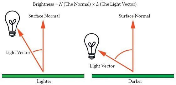
FIG 10.3 The normal and the N × L calculation.
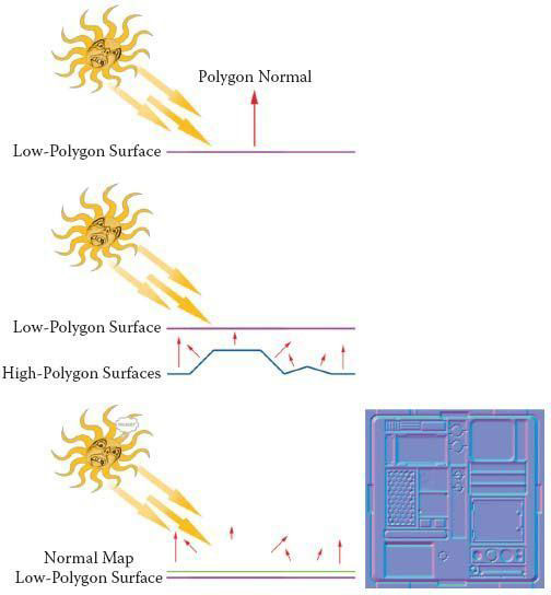
FIG 10.4 A normal map.
Creating Normal Maps in Photoshop
An easy way to create normal maps is to create a grayscale map in Photoshop and use the NVIDIA plug-in to convert it to a normal map. There are several techniques for building these maps: painting them, creating them from photos (source-based), and using parts of existing normal maps.
Painting Normal Maps
An easy way to create a normal map is to create grayscale height maps and use a filter (freely available from NVIDIA) to convert them into normal maps. In Figure 10.5, you can see the height map, the NVIDIA interface with 3D preview, and the resulting normal map. You can see that using various shades of gray and creating soft or hard edges you can create almost any object you need in a normal map.

FIG 10.5 Normal map creation using varying grayscale values and softer or harder edges.
Source-Based Normal Maps
A source-based normal map is one that is created from an image—usually a photo. Although this is not always desirable, you can get some good results from a photo. In most cases, when creating environments for a game, the textures that you will be creating won’t all be for rounded, injection-molded plastic spaceship interiors. Most textures are for stones, concrete, tree bark, wood, and hard-edged objects—and a lot of other surfaces that are almost impossible to model and shoot normals for. You will often be in a situation where you have to use a photograph, or finished texture, to create a normal map. The steps to do this are as follows:
1. Start with a copy of your image and desaturate it. I often convert the image to 16 bit, as any banding in the image will show in the normal map. It will look like a topographical map (Figure 10.6).
2. Run the Photocopy filter. You will have to adjust the settings based on the source image, but the goal is to get the lower parts of the image to be black and the higher to be white with little distortion. Figure 10.7 shows this and the following steps.
3. Darken the areas that are supposed to be deeper than the overall surface. In this example, I darkened the area where the bricks are exposed, as the plaster is on top of the layer of bricks and should be set back in relation to it.

FIG 10.6 Banding in the normal map.

FIG 10.7 Creating a normal map from a photo.
4. I cleaned out a lot of the noise from the overall image, as normal maps are very sensitive and usually an excess of detail on a normal map translates into a noisy and/or puffy result.
5. I took a very small brush and darkened the major cracks in the wall and put a 2-pixel Gaussian blur on the entire image. This entire process takes only a few minutes and adds a great sense of depth to the image.

FIG 10.8 Various strengths of the normal map created from the photo.
6. You can build up more depth in your normal map by taking the normal map into Photoshop and creating a layer via copy and setting the Blending Mode to Overlay. This step alone will enhance the detail of the normal map.
7. If you blur this layer a few pixels, that adds more depth. You can repeat this process several times—duplicate the layer and blur it (making sure that the Blending Mode is still set to Overlay) and check the results every so often until you like what you see. This extra step is great for more organic textures, as it builds depth in a way that makes the details more rounded. Hard details are still best painted in if you are working in Photoshop.
8. The last thing to do is to renormalize the map by running it through the NVIDIA filter and checking the Normalize only option. This step corrects any vector information encoded into the normal map that we might have corrupted during these steps (Figure 10.8).
Use Parts of Existing Normal Maps
This method can be used in 2D as well as 3D. In 2D, you are simply cutting and pasting parts of existing normal maps and putting them together; in 3D, you are putting various parts or geometry together to create the normal map. The 2D parts can be moved about to be effective only as parts of a normal map, but the 3D parts can be moved, scaled, rotated and reused in many more ways.
Creating Normal Maps Using a 3D Program
The process for creating normal maps using a 3D application starts with the two models: a high-polygon model (the sky’s the limit on detail) and a low-polygon model (needs to run in the game engine you are creating it for). It doesn’t matter which one you create first, but there are some pros and cons to both approaches. After the two models are created, the process generally involves arranging the two models so that they are on top of each other and generate the normal map correctly. This step can be the most time-consuming and frustrating. When the application that generates the normal map is run, it is doing the following:
• Mapping an empty texture to the low-polygon model
• Calculating, for each pixel of the empty texture on the low-polygon model, the corresponding normal from the high-polygon model
• Recording that information in the texture map as an RGB value
This method is required for very highly detailed characters and some organic props, but the time and effort spent on this for environmental art (walls, floors, control panels, and so on) is overkill—and often produces inferior results. If you can’t achieve your result quickly in 2D and you have access to a 3D application, here is a method for the quick creation of normal maps in 3D. Essentially, you model all of your high-polygon details as separate parts so you can arrange them and shoot the normal map once (Figure 10.9). In fact, a simple prop with a few sides can more easily be modeled and normal maps shot by building all the separate faces of the model flat (similar to laying out UVs, only in 3D) and shooting the normal maps and assembling them in Photoshop. I have seen inordinate amounts of time go into normal map creation for things as simple as vents on a wall (I am talking about days), when it should have taken under an hour the first time and only moments in the future, as the asset can be reused.

FIG 10.9 Creating normal maps in a 3D application: the quick way.
Assets for a Futuristic Interior
The assets for this futuristic interior mostly involve the creation of the textures for the shaders. The models themselves are purposely very simple for this exercise so that you can see clearly the power of the normal maps and other shaders when applied to even the simplest of geometry.
Texture list:
• Wall panel
• Floor panel
• Light/ceiling panel
• Column
• Door
• Monitor
• Pipes and hoses
Wall Panels
Let’s start with a wall panel. As we know we are creating a shader that will involve multiple maps—diffuse (color), specularity, illumination, opacity, and a normal map—we need to set the Photoshop file up so that each map corresponds exactly to each of the other maps. Say you are creating a light panel where the frame protrudes from the surface, the light panel is bright even in darkness as if the light were on, the paint is scratched away, and the exposed metal shines brighter than the remaining paint around it. All the images created for use in the shaders that will produce all those visual effects need to line up exactly. If these images are not created in an organized fashion so they line up perfectly, you will get many undesired effects that will shatter the illusion you are trying to create. Misaligned maps will create lit parts of a texture that should be dark, as well as normal bumping where things should be flat (picture the image of a nail head in a wall and a few pixels over a bump that looks like a nail head). No map is immune! The specular map needs to line up perfectly with the materials in your texture. Scratches and chipped patches of exposed metal need to shine and the shine needs to stop right where the exposed metal stops and the paint starts. Of course, Photoshop layers make this easy. This approach also allows for the rapid iteration of changes in each of the maps. Setting the file up right will greatly speed up your work, as all the maps created can be produced based on the first few layers you create. I usually start with a simple layout of the texture. For the wall panel, this is a black-and-white layout of the shapes of the panels and parts of the wall panel. You can see in Figure 10.10 the layers that compose the group for the shapes in the panel. From this I usually create the normal map right off to see whether the concept can be achieved in 2D (Figure 10.11).

FIG 10.10 Black-and-white layout of the shapes of the panels.

FIG 10.11 Normal map to see whether the concept can be achieved.
Color
Start with the group that we just created for the layout of the panel, and copy it. Name it diffuse or color. For the diffuse map, the stark black and white of the layout is all taken way down (use Fill and not Opacity to do this so that the layer styles are not affected). Having the shapes all on separate layers will make texture creation easier on each map, for various reasons. On the color map, you can use the various layers to apply subtle layer styles—a slight dark outer glow, for instance, to create the look of dirt in the cracks. You can use a color overlay to try out various colors quickly and when you like what you have, you can sample the color to create a paint layer.
To create a great layer of peeling paint, use this common trick that will net you impressive results. Create a new layer on the top of the stack and select the paint bucket. Check the All layers box, select a nice desaturated color, fill an area, and watch what happens. To get different results, try playing with the tolerance of the tool. You can also try masking off specific areas so that the paint only fills that area; this can be good for trim or panels. You can also use a pattern fill; that is how the caution stripes were done in Figure 10.25 on the door.
Create the paint layer last and on top of the stack, but you need to move this layer under all the overlays for it to look right, with the weathering and stains on top of the paint. Try a one-pixel, very slight bevel on the paint to give it some perceived thickness. Use an equally subtle dark outer glow to help enhance this effect.
Having any parts that need illumination on their own dedicated layers makes it very easy to create the illumination map later on, too. This applies to all the maps—even the specular map is easier when you can quickly isolate a panel using a Ctrl-click on a layer. By creating your overlays for dirt and scratches—and other elements of color, such as stenciled writing or stickers—on separate layers, you can use these layers as a basis for each new texture you create, so that all the surfaces of the space you are creating will have a consistency in the wear and tear and overall look (Figure 10.12).
Illumination
The illumination map is created by creating a new layer filled with black and Ctrl-clicking on the layers with the parts that will be illuminated—the color of the lights for this panel—and inverting the black to white on the new illumination layer (Ctrl+I). In this case, the only lights present are the two fluorescent-type tubes on the bottom of the panel. In Figure 10.13, you can see the difference between the texture with and without the illumination map present.
Specularity
The specularity map is a copy of the entire texture that is darkened; because the various parts of the texture are on layers, we can Ctrl-click the layers to get precise control over the specularity of various elements of the surface such as the paint. The paint is all chipped and peeling; by selecting this layer’s transparency, we can take the brightness up or down to make the paint uniformly shiny or dull. We can also dodge in scratches and scrapes. Remember that the white will be shiny and the black dull, so the edges of panels and around handles will be scratched and shiny. You can also paint with a white brush on a separate layer if you want to have more control over the effect and the ability to redo and fix things more easily later. In Figure 10.14, you can see the texture with the normal map, the specularity map, and then all three together in the foreground. Another thing to keep in mind is that deep cracks and spaces shouldn’t have any specular reflection; this is one of the many reasons that many normal maps often look like molded plastic.

FIG 10.12 Overlays for dirt and scratches and other elements such as stenciled writing or stickers. These overlays can be used on each texture you create, so that all the surfaces of the space you are creating will have a consistency in the wear and tear and overall look.
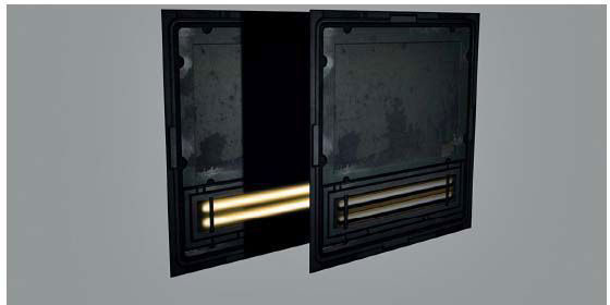
FIG 10.13 The texture with and without the illumination map present.

FIG 10.14 Rear, the diffuse texture with the normal map applied; middle, the specularity map by itself; and then all three applied to the mesh in the foreground (diffuse, specularity, and normal maps).
Normal Map
The normal map starts out as a grayscale image, and I do many iterations with the NVIDIA normal mapping filter in Photoshop several times until I get the desired result. There are a few things to keep in mind when creating normal maps in this fashion:
• Watch for banding in the normal map. If this is a problem, work at a higher resolution, take the image mode up to 16 bit, and make sure that the brush you are using is not only soft, but that the “spacing” is set as low as possible under the brush tip shape of the Brushes palette.
• If you want to create multiple layers of depth, do this by working at multiple levels of grayscale. Two objects crossing each other will look as if they are on the same level and mashing together, rather than on separate levels, if they are using the same values. Make one darker so it seems farther back; Figures 10.15 and 10.16 illustrates the effect of changing the grayscale values.

FIG 10.15 Multiple layers of depth.

FIG 10.16 Grayscale value changes.

FIG 10.17 Dirt caution.
• Remember that normal maps are very sensitive to value changes. If you want to include dirt on your normal map, the difference in value for the surface it is sitting on should be very subtle. Brighten the surface slightly and the dirt will protrude; darken it and the dirt will look like pits and dents. You may want to consider adding dirt last, after you have tweaked the major height appearances of the normal map. If you need to increase the values of the overall normal map at any stage, that also means that the effect of the dirt protruding from the surface will increase and it will end up looking like huge lumps (Figure 10.17).
• Save interesting objects that you build normal maps for and create a library of vents, panels, controls, and so on.
Wall Panel Variations
By saving a copy of the file that you just created, you can make variations on the wall panel—without lights or half-sized or with different panel designs. By using the existing file, you can keep the texture visually consistent (Figure 10.18). In Figure 10.19, you can see more details for the open wall panel. This was constructed in the same manner as the other panels, only there is added detail—more panels and lights. Because there is so much detail in the normal map, I found that as I worked, some parts looked good and others needed more work. I wanted to continue to make some parts more prominent, so I simply saved a copy of the normal map at that stage and kept working. Later, I combined the versions of each normal map and kept the parts I liked best to create the final normal map. In this case, I wanted to make the panels more prominent, but that made the hose connectors too puffy, so I put the final normal map on top of the version with the good hose connectors and erased the connectors from the top layer. Remember to merge and renormalize. This is as complex as the geometry for the walls and floors gets at present (Figure 10.20).

FIG 10.18 Wall panel variations.

FIG 10.19 Wall panel open.

FIG 10.20 The geometry of the scene—it’s very simple.
Floor Panels
Creation of the floor panels starts from the wall panels, but being on the floor, these textures can be simpler (Figure 10.21). They feature some diamond plate and caution stripes. I created a half-sized version with the caution stripe on it to be used around the edges of the hall (Figure 10.22).

FIG 10.21 Large floor panel.

FIG 10.22 Half-sized floor panel.

FIG 10.23 Column.
Column
With the column, we introduce a slightly more complex mesh than the flat polygons of the floor and walls (Figure 10.23).
Light/Ceiling Panel
The light panel (Figure 10.24) has only one unique texture for the grate. The others are wall panels and the lights themselves are from the wall panel with a light. There is also the introduction of the opacity map. Although the illumination map can be a little fuzzy (so it appears that the area around the light is being lit), the opacity map needs to be precise if you want the grill to look clean. If it’s fuzzy, there will be a fading of the texture.
Door
On the door texture, I included the frame parts as well (Figure 10.25). The surface behind the door is a wall, so I textured it accordingly.

FIG 10.24 Light panel.

FIG 10.25 Door.

FIG 10.26 Monitor.
Monitor
The monitor (Figure 10.26) has a few overlays for the screen, and in addition to the illumination map, there is an actual light source in the scene that helps make it glow. The mesh is simply a line extruded, and the front face beveled.
Pipes and Hoses
With the ability to add more polygons to our scenes, we are now able to include traditionally high-polygon (relatively speaking) objects such as hoses (Figure 10.27). Hoses are round and can be curvy—round and curvy means polygon-intensive. Start with a horizontally tiling texture for a few hoses and a pipe or two. The fact that we can use a specular and normal map on the hoses allows us to create a really cool texture on the hoses (Figure 10.28). Figure 10.29 shows a render of the final scene with and without the shaders in place.

FIG 10.27 Pipes and hoses.

FIG 10.28 Hose detail.
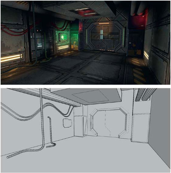
FIG 10.29 Final scene.