Shaders allow for a stunning level of realism in games, and the rate at which the hardware is improving is staggering. I purposely wrote this book to address core principles of game art creation that don’t change or that change very slowly. Hardware and technology change rapidly, but that doesn’t alter the basics of texture, shader, and material creation—at least not yet. Figure 3.1 shows some recent screenshots provided by Unigine Corporation of shaders in action. The top scene is from Tropics, a benchmark demo that depicts tropical paradise using many shaders: ocean waves stretch off into infinity and undulate, sparkle, refract, and so on. The lagoon islands have sandy beaches with crisp shadows and crawling crabs. There is a ton of detail in this one shot alone as the sun sets on the scene, bathing the huts in color and shadow. The vegetation sways as a gentle ocean breeze passes through. In the animated version of this image (running in real time as a game), you can see the waves crashing on the shore and the clouds moving; there is a lot going on! The two following images show the DirectX 9 version and the DirectX 11 version of the same scene. You can see that the roof and stonework in the building are the places of the most distinction between the two scenes. In the image on the left, the stonework is flat; in the right, it stands out prominently, even casting shadows. This is because DirectX 11 now uses tessellation, which is one of the more important DirectX 11 features. Tessellation uses a height map to determine the extent to which a feature should protrude from a surface and actually divides up the mesh and pushes the geometry out from the surface.

FIG 3.1 Upper image: The Tropics benchmark demo from Unigine Corp. Notice the water. It is actually moving in the demo and crashing on the shore and refracting so that the sunken boat is distorted by the waves. Lower image: The two images look almost the same, but the upper one uses DirectX 9 and the lower DirectX 11. With DirectX 11 we can use tessellation, which adds all that detail (protruding stones) in real time.
DirectX 11, the current version, is beyond amazing to me. I can’t go into technical comparisons and discussions without filling a book, but in the last two years alone the graphics card that was top-notch when I bought it runs a game I have at about 10 fPS and the newest cards will run the same game at over 100 fPS. And that is not even a fair comparison because the newer cards are doing so much more in real time. I am purposely vague here because there are so many variables and the technology improves so fast it would be a waste of time to discuss it more at this point.
What this means to you is that although you may create a texture, a shader, and a material in the same manner for one card or the next, the size of the textures, the number of effects and polygons, and so on that you can have in a scene will all go up. This number needs to be assessed when the game you are developing is in the process of being developed.
Simply put, a shader is a mini-program that processes graphic effects in real time. For example, the reflections on a surface can move in real time instead of being “baked,” or permanently painted, onto a surface. Shader effects are very powerful visually, even if viewers are unaware of what they are seeing; the average player would have a hard time defining why the game that he or she is playing looks so good. This level of quality may be due to the real-time reflections, normal mapping, or the specular mapping being processed in real time.
Ever since these technologies started rapidly advancing, there has been talk that procedural textures and advanced technologies would one day replace the artist. This will never happen. As amazing as the technology is, it still takes an artist to make these technologies produce the best visual results. In fact, the artist has become more important than ever as technology has become more complex. Although programmers give us incredible new technologies, the artist is still needed to create and control the input and output of those systems.
There are two main types of shader on modern graphics processors (GPUs):
• Vertex shaders manipulate geometry (vertices and their attributes) in real time.
• Pixel shaders manipulate rendered pixels in real time.
The ability to manipulate an individual pixel or vertex in real time is what makes shaders so powerful; it is also what makes them so processor-intensive. On one hand, we can simulate virtually any condition using shaders; on the other hand, they devour resources. For each frame displayed, all the shader effects for that frame must be processed (or rendered), which takes time. Although each amount of time required is miniscule, it adds up as millions of individual pixels and vertices are processed. Shaders can be used for many complex material appearances and image effects: hair, fire, shadows, water, reflections, and so forth. Shaders are so flexible that the list of possible effects is almost endless—a shader programmer can write almost any imaginable effect. Interestingly, although only very recently has consumer-level hardware been able to handle the intense demand that real-time shaders put on a system, the knowledge of these processes has been around for decades. In fact, many of the techniques that you will read about here are based on algorithms named for well-known mathematical geniuses. For instance, Phong and Blinn are recognizable names if you are a 3D artist.
Remember that the ability to manipulate an individual pixel or vertex in real time is what makes shaders so powerful. Very recently, real-time lighting began being calculated per vertex, not per pixel—that is, lighting is now often calculated for an entire face of a polygon, not for every pixel. This ability is significant because it not only adds a great degree of detail and smoothness but also allows for shaders such as normal maps to function.
But how does all this work? That brings me to the large fuzzy overlap between programming and art. Granted, these are two very different activities, and there is a line between how much art a programmer needs to understand and how much technology an artist needs to understand. Exactly where that line is, no one can say precisely, but when it comes to shaders, you should understand the basics of how the technology works.
Wait! Don’t fling the book across the room just yet. You don’t need to know the math behind it all, just a simple explanation of how it works.
A shader, from the artist’s point of view, is often a bit of a black box. Our involvement usually requires that we generate input for a preexisting shader—set parameters and/or assign textures and then look at the end result. Because the artist’s role is mostly confined to creating input and judging the output of the shader, we often have nothing to do with the code. In some cases, shader code is written or edited by an artist, but most newer shader creation tools are more like the material systems in Max and Maya, requiring no programming knowledge. Figure 3.2 shows a couple of examples of how a material shader works from the artist’s point of view.
Shaders often require the use of 2D assets as input, and the artist is usually the one tasked with not only creating those assets but also understanding, creating, and implementing the shader to some degree. So, although shaders can perform much of the work that an artist would do on an asset, they may also increase our workload. Already there are effects in games where the artist is no longer painting a texture as an isolated entity but is creating a series of textures that must all work together for a desired effect. Using shaders requires more planning, a different way of thinking about creating the art, and more organization. The artist needs to learn the shader tool, organize more assets (assets that may be linked to one another and are therefore more rigid in their mobility after a shader is in place), and learn the mental discipline of creating assets that are not the end result but component parts of a final result.
We have to get accustomed to painting textures devoid of certain properties that will later be processed in real time. One reason we need to understand the fundamentals of light and shadow or to develop the skill to see the base material of a scene behind all the dirt, reflections, and other surface properties is that we may soon be building textures starting with a very plain surface (even a pattern) and building a complex organizational tree of maps and effects to create a final surface—much as we already do in 3D programs and like the way some texture generators work. For example, the highlights on the armor in Figure 3.3 are controlled by a shader. With no specular highlight, a surface can look flat and dull. With a generic specular highlight applied evenly to the surface, things will often look plastic and fake. Using a map to control the specular highlight, we can make a surface look much more realistic. Although shaders can make our lives easier in some respects and they can definitely make our games look better, they can also be a bit complex to understand at first and require a greater degree of organization.
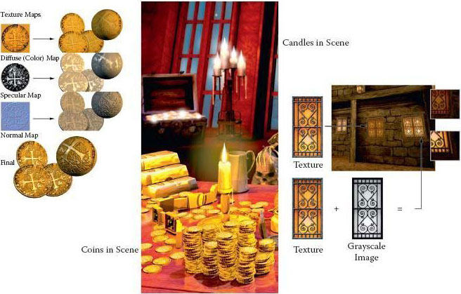
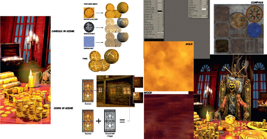
FIG 3.2 Here is a simple flow showing how two shaders work for the artist. The illumination map is applied to the texture of the window to make the proper parts of the window glow with light while leaving the frame dark. The coin, a simple cylinder, is mapped with a diffuse or color map, a specular map, and a normal bump map. You can see the final result at the bottom where the effects of all three maps are combined. In the middle the scene on the front cover uses these techniques on the coins and candles.

FIG 3.3 Instead of painting a highlight onto a surface in Photoshop, you can now leave it out and assign a shader. The cover scene uses specularity maps in many places; in the pirate king’s throne the carvings are enhanced using a specularity map.

FIG 3.4 From right to left: The UV template, the diffuse map created from the template, and the model wrapped with the texture. The left side of the face was left unmapped so that you can see the original mesh.
Some of the most common shaders today require images that are easily created and manipulated in Photoshop. The most common of these are the color map (or diffuse channel), the bump and normal maps, specularity maps, illumination maps, and opacity maps. In general, a game artist creates textures meant to be tiled over an area or mapped to an object. When the texture is to be mapped to an object, the artist starts the creation of the texture with a template. Whether a complex character skin or a simple prop, this template is generated from the UV coordinates that have been mapped out onto the 3D model. After the basic color information has been put into place, the other shader maps are often created from the initial color map, the 3D model itself, and even some hand painting. The UV map represents the exact way in which the 2D art will be mapped, or wrapped around, the 3D model. In Figure 3.4 you can see how the template was created from the actual face model and the simple prop and then used as a guide to paint the textures. We will be working with templates later in the book.
Like most issues related to computer game technology, shaders are a vast and complex topic riddled with new vocabulary, concepts, and technological requirements. In addition, each game engine and each game project will have its own vocabulary, process, and subtle nuances in dealing with shaders. But you will always deal with some basic shader effects, and here are some samples of them. You may notice that these shader effects are very similar to filter effects in Photoshop, materials in Max or Maya, and many post-video effects. Post-video effects are effects inserted into a film or video during the editing process, after the footage is shot.
In this chapter we look at not only what these shaders can do in a cursory sense but also some of the ways you can get various effects with these shaders. The following is a list of basic shaders and material types that you will most likely work with in game development:
• Diffuse (color maps or textures)
• Blend
• Detail mapping
• Depth of field
• Heat haze
• Specularity
• Bloom (glow or halo)
• Masking and opacity
• Illumination (emissive)
• Reflection/cube mapping
• Pan/rotate/scale
• Normal, bump, and parallax mapping
• Tessellation
Diffuse (Color Maps or Textures)
The term diffuse map has many meanings, depending on the software you use and your educational background. I will spare you the technical and scientific definition and simply tell you that a diffuse map in the game industry generally means the color map or texture, an image containing only the color information of a surface. This is not to say it is devoid of all detail. Because game engines still don’t reproduce the visual world 100% accurately, we still need to fill in the gaps. We can do this with subtle detail in the color map that is supported by the other maps. Areas in the texture where light would be noticeably brighter or darker can be defined to some degree. The spaces between metal panels and wood planks are examples of where some darkness could be painted in with good effect.
In Figure 3.5 you can see the diffuse map for an old pirate. There is probably a bit too much light and shadow information in the texture. The prominent highlights and shadows on the veins and wrinkles are especially noticeable, so I would take them down and replace them with a normal map if this were to be used in real time. There is a normal map on this mesh, but I relied on the color map a bit more because I created this mesh for a specific use at a fixed angle and the normal map didn’t need to behave perfectly.

FIG 3.5 The diffuse color map can contain a good deal of information, but currently the use of per-pixel lighting makes this unnecessary and often undesirable.
Cracks and seams are places where dirt is most likely to collect, which would further add to the darkness of such parts of the texture. Technically, you can handle these cracks with the normal map and other effects, but I find that relying too heavily on one map type often results in plastic-looking materials.
Originally, game artists had only the diffuse channel to work with, and essentially what you created in Photoshop was what you saw in the game—all shadows, highlights, and details were contained on the color map and were static (or “baked in”). This image was typically of low resolution and color depth and was wrapped around a low-polygon model—presto, you had a game model. This process has changed quite a bit in the last few years. With the advent of new technologies that require a slightly complex separation of visual components into a series of separate assets that are processed together to create the final effect, the color map has become much more simple and subtle. That is, it’s simple and subtle in terms of other information aside from the color itself, but it’s richer in color detail because we can now use images that have much larger resolutions. In some ways, this method of asset creation is harder to grasp and execute, but in other ways it is actually easier—especially for a trained artist who already understands how the visual world works.
The color map in Figure 3.6 contains the base color of a character’s skin. In addition to the skin tone, however, the color map also must convey subtle details that either can’t be depicted by the technology or are simply so subtle it may be quicker to paint them into the color map than try to reproduce them technically. Human skin is so subtle yet complex that often the qualities of skin (such as age and condition) and the details of skin (such as small veins, creases, spots, freckles, and pores) are best portrayed on the color map. Human skin is not one smooth color but rather is composed of many colors and interacts with light in a unique way. Such a map can take a long time to produce, since it requires a balance between subtlety and clear detail. Too much contrast, saturation, or other attribute and the character starts to look diseased; not enough and the character looks like a mannequin.

FIG 3.6 The diffuse color map of human facial skin. Even with complex shaders, the skin on a human face is so full of subtlety and detail that we still need to have some detail in the color map.
Blend
The blend shader blends two textures together; depending on what software or game engine you use, it may blend in a default fashion or offer various modes that are very similar to the blending modes in Photoshop. The blending usually occurs between a base texture and one or more textures on top of it. Each layer has its own set of UV coordinates, so you can have one small tileable texture that repeats as your base and blend other textures, such as stains, cracks, and other details, on top. This method not only takes up less texture memory but also allows for a great deal of variety because there are so many options for blending numerous textures together. The basic blending modes follow and are displayed in Figure 3.7:
• Average
• Additive
• Subtractive
Average Mode
Average blends the colors of the base map and the new map evenly. If you don’t want either texture overpowering the other in any way, use the average mode. This mode is appropriate for creating an entirely new texture from two separate textures or, in conjunction with grayscale base maps, for coloring the base map.
Additive Mode
The additive color model brightens the base map. Black becomes completely transparent.
Subtractive Mode
The subtractive color model darkens the base map with the new image. White becomes completely transparent.
Detail Mapping
A detail texture is a layer laid on top of a low-detail color texture. Players can see the detail texture from their point of view, but the detail texture fades in as they move. This allows the texture (the ground, for instance) to look very detailed. Detail textures are usually grayscale images that add detail to the color map below it, using one of the blending modes discussed previously. Detail textures can be used to add detail to stone, metal, wood—any surface in the world (Figure 3.8).

FIG 3.7 Various blending effects using the blend shader.

FIG 3.8 Players can see the detail texture from their point of view, but the detail texture fades in as they move.
Depth of Field
Depth of field in photography is the distance in front of and beyond the subject being focused on and photographed. A shader can create the illusion that objects in the background are far off by blurring them, thus causing a depth-of-field effect. You can adjust the depth of field, just as you can in photography, so that the area in focus can range from infinite to very narrow or shallow. A shallow depth of field means that objects are in focus only in a very small area. Depth of field can be so shallow that a very close-up picture of a coin can have one side of the coin in focus and the other totally blurry. Figure 3.9 shows an example of depth of field.

FIG 3.9 This shader creates the illusion that objects in the background are far off by blurring them, thus causing a depth-of-field effect.
Heat Haze
Heat haze creates the shimmering effect you can see emanating from very hot objects or the ground on hot days. Figure 3.10 shows the effect applied to the exhaust pipe of a vehicle.
Specular Highlights and Glossiness
A specular highlight is that bright spot that appears on most surfaces when light hits. That spot can be small and bright or large and barely noticeable, depending on the quality of the material the light is hitting. A specularity map allows you to control this effect, and you can even use a mask to control how various parts of the same surface display the specular light differently. A good example is beaten-up metal armor. You may have a layer of old paint and dirt that will not be highly reflective and areas where this coating has been worn away to reveal reflective metal, which is metal that has been polished by constant wear and tear (Figure 3.11). Sometimes glossiness is separated from the specular highlight; the distinction is that glossiness determines the size of the specular highlight, and specularity controls the intensity of the highlight.

FIG 3.10 The bottom muzzle blast has the heat effect present.

FIG 3.11 A specularity map and examples of specular basics.
A specularity map controls what parts of the surface are shiny or dull based on the grayscale value of the specularity map. You can see that the armor has no specular control on the left, and the middle and right have two different specularity maps. Specularity maps are generally created from the color map. In Photoshop you simply desaturate a copy of the color map and adjust from there. You can see the exact spot where the grayscale image is affecting the specularity on the model (Figure 3.12).

FIG 3.12 Specularity map.
Bloom (Glow or Halo)
Blooming makes a light source appear brighter than it really is by spreading the light source out over the edges of the object it is on. A bright light will appear to bleed over onto objects around it, both in front of and behind the object. Usually this effect is achieved by creating a glow around the light source that is blended with its surroundings, but sometimes the engine actually processes the entire screen. Using several render passes, it will multiply the frame (like the Photoshop blending mode, this lightens the lighter areas and darkens the darker areas), blurs the image, and then draws it on top of the original screen. Blooming helps create the illusion that a light source is brighter than it can actually be displayed by the monitor. See Figure 3.13.
Masking and Opacity
Masking typically uses a specific color that is designated as the “clear” color and is more efficient than transparency. Transparency uses a separate channel or grayscale image to determine the opacity of a pixel. The trade-off is that transparency looks better, but it requires more file space and more processing power. Masking can significantly speed up a huge scene that has tons of overlapping elements with transparency on them, such as a forest or jungle. In Figure 3.14 you can see examples of masking and transparency. Figure 3.15 shows the interface of the NVIDIA tool that allows for the rapid adjusting and viewing of textures before outputting them.

FIG 3.13 Bloom shots. Light glow, with full-frame processing.
Opacity maps determine whether an image is solid, transparent, or somewhere in between. Opacity is generally best used when there is a need for transparency, as on windows, and/or subtle ranges in opacity, such as seen in smoke and fire. Although masking can do the job for tree leaves, fences, and grates, opacity is better for in-game effects such as explosions, fire, bullet holes, smoke, and particles such as rain and magic sparks. In Figure 3.16 you can see various examples of such effects.
Illumination and Unlit Textures
An unlit texture and a texture with an illumination map applied to it are two different things. An unlit texture is simply a texture that is unaffected by lighting and displays at 100% brightness under all conditions. An unlit texture can be known by other names, such as a full bright or a self-illuminated texture (Figure 3.17). In Figure 3.18 you can see an example of an unlit texture on a particle that looks better unlit and also runs faster. An illumination mapped texture, sometimes known as an emissive texture, uses an additional image (typically a grayscale image) to control the portions of the texture that are lit and to what degree. When you use an illumination map, additional calculations must be done and additional resources used for controlling the lighting on a texture this way. So, whereas the fully bright texture can make things run faster, the addition of the illumination map to a texture creates more processing demands and requires more memory to hold the additional map and can therefore slow things down.

FIG 3.14 The upper portion of this figure shows an image of some grass with an alpha channel; the lower shows a color mask. Notice that the images look virtually identical from afar. It isn’t until we are very close that we can see the jagged edge.

FIG 3.15 The interface of the NVIDIA tool. The three most common masking and alpha formats have been highlighted.

FIG 3.16 Particle examples.
Reflection
The reflective nature of a surface can be like a mirror (100% reflective) or completely matte; a rough wood may have no reflection at all. Real-time reflections can be very draining on the computer, so there are ways to fake reflections using environment or cube mapping.
There are many ways to generate reflections in a game, but the most common and easiest to implement is the cube map. A cube map is a series of images that the environment map uses to fake the reflection on the surface of an object. Cube maps are so named because the reflections you see are actually six images arranged in a cube and projected back onto the reflective object. These images are rendered from the location of the reflective object so that the cube map reflects the objects’ surroundings accurately. These six images cover all directions: up, down, front, back, left, and right. Ideally they all line up, meaning that the images meet at the edges so that the reflection is seamless. The images of the cube map are most commonly static, meaning that they are always the same. If you are looking into a reflection created by a static cube map, you won’t see yourself (or your in-game character). This is the most efficient way to handle cube mapping, but there are also other techniques for generating real-time reflections. One of those techniques is called dynamic cube mapping. This method redraws the six images in the cube map every frame. If the object mapped with the environment map moves or something in the environment around it moves, the cube maps are updated to render an accurate reflection in real time.

FIG 3.17 Image 1 is the control panel texture, and to the right is its illumination map; image 2 is a version of the control panel where the lit parts are slightly blurred, as are the corresponding bright parts on the illumination map. In image 3 you can see the control panel in a darkened setting and the control panel unlit (or full bright), and in image 4 you see the illumination-mapped versions. By blurring the portion to be lit in the color map and the illumination map, a glow effect is simulated.
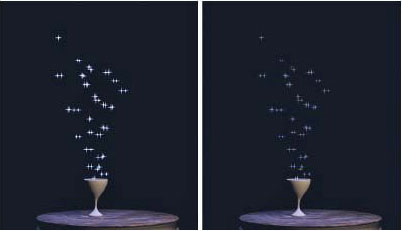
FIG 3.18 Magic particle unlit and lit.
Figure 3.19 shows how the (static) cube map was created for the pitcher. Notice the maps arranged as though the cube were folded open like a box. The six images that form the cube map were rendered from the location of the pitcher, so the metal looks as though it is reflecting its surroundings from the proper position. You can even use a simple cloud image as a cube map and get some great results (Figure 3.20). I did nothing more than use cloud images for each face of the cube map, and the armor looks like it is made of silver. The neat thing is that in a game, those reflections would move with the armor and look so much more convincing than a static image of a reflection.

FIG 3.19 This cube map was created for the pitcher. The metal looks as though it is reflecting its surroundings from the proper position.

FIG 3.20 With a simple cloud image as a cube map, this armor looks as though it were made of silver.
Pan/Rotate/Scale
Often shader systems give the artist the ability to pan, rotate, scale, and otherwise move a texture in real time, which can be useful to convey the movement of elements on a computer screen or fluid through pipes or to create a moving walkway. This capability has been used to animate waterfalls and rotating fans. In Figure 3.21 you can see the simple concepts of panning (moving vertically or horizontally), rotating (turning), and scaling (making larger or smaller). You can also see that to make a wheel look like it is turning, we must pan and rotate the texture. You should be aware that although this figure illustrates the concept, chances are that in a 3D game the mesh the texture is on, not the texture itself, would turn and move. I have used a scrolling and panning smoke texture over a simple laser light texture with a great “dust in the laser beams” effect (Figure 3.22).

FIG 3.21 Panning (moving vertically or horizontally), rotating (turning), and scaling (larger or smaller).

FIG 3.22 Scrolling and panning smoke texture over a simple laser light texture for a “dust in the laser beams” effect.
Bump, Normal, and Parallax Occlusion Mapping
The bump, normal, and parallax occlusion mapping shaders add 3D depth to an otherwise flat surface. Bump maps are grayscale and display the most limited 3D effect; the others add depth using a color map with lighting information encoded in it. These shaders are all similar in what they accomplish, but depending on the exact code of the shader and the supporting hardware, the effect can range from really cool to absolutely awesome. A basic normal map adds a level of depth deeper than the bump map, but more advanced forms of these shaders add details and behaviors such as self-occlusion, silhouetting, and self-shadowing. Figure 3.23 is a simple visual demonstration of how the shader operates. Because we can calculate the light of the surface for every pixel, we don’t need to include geometry to create shadows and highlights as we did when we lit per polygon. We can now tell the 3D application to treat each and every pixel as if it were reacting to light, as it did when it was on the high-polygon model.
Have you ever seen a mural or painting that looked real, but when you changed your viewing angle, you could suddenly see that it was fake—a flat, 2D image? The light and shadow didn’t move. The artist painted it to be viewed from that one angle, so it only looks good from that one angle. Imagine if you could create a painting that quickly repainted itself every time you moved, so it looked as though you were seeing a real three-dimensional scene. That is essentially what a normal map is doing as it calculates light and shadow in real time. We still need to maintain the silhouette of the model as best we can. Using a present-day “vanilla” normal map allows us to focus more polygons on the silhouette of the model, which is a benefit. But there is also a drawback: It means that the normal map cannot change the silhouette. Back to the painting analogy: Even if a painting can be repainted so quickly it looks real, there is a limit to the effect. When you move too far off on an angle, you will see that it is just a flat 2D painting that is updating in real time. That is how a basic normal map works. But more complex versions of normal maps can actually move the pixels in real time and change the silhouette when viewed from the side; this would be like the canvas of the painting actually pushing out to form the detail painted on it.

FIG 3.23 A simple visual demonstration of how the shader operates.
In short, a normal map is an RGB image that records all the light and shadow detail from a high-polygon model. When this map is applied to a low-resolution model, the light and shadow are calculated as though the light were hitting the high-resolution version of the model. The idea is actually simple to understand. (Of course, my standard disclaimer of how tricky this is for a programmer goes here, but seriously, we artists have the fun part of the development process).

FIG 3.24 A surface built up using images created in Photoshop.
Although the best normal maps are typically generated from very highly detailed 3D models, you can get a free Photoshop plug-in from NVIDIA (http://developer.nvidia.com) that will generate a normal map for you from a 2D image. There are many other tricks for creating normal maps entirely in Photoshop, and we will use them later in the book. This method is especially easy when we’re creating environmental art, since the surfaces we work with tend to be much simpler than the surface of a character. In Figure 3.24 the surface was built up using images created in Photoshop; even the normal map was created as a black-and-white map and exported as a normal map. You can see the grayscale image used to create the normal map and the surface with nothing applied to it. Then you see the color map only, and the normal map only, and finally the surface with all the maps applied. We look at normal mapping in much greater depth later in the book and actually create normal maps using a few different methods.
Tessellation
One of the coolest new features of DirectX 11 is tessellation. The process of tessellation is straightforward: You take a polygon and chop it into many smaller parts. DirectX 11 and the newest hardware can do this in real time. This is cool when you combine the newly tessellated surface with a black-and-white displacement map. When these tools are used together, a surface can take on very impressive detail; see Figure 3.25.
With DirectX 11 we can finally use displacement mapping to its fullest potential because we can also perform tessellation in real time. Tessellation doesn’t suffer from the limits of bump and even normal mapping; those are illusions of detail whereas tessellation is actual geometric detail. The need to no longer create normal maps is a huge boon. Now you can paint a highly detailed model in 3D and export a displacement map to use on a low-polygon version of the model.

FIG 3.25 A tessellated surface with a displacement map can make a surface take on very impressive detail. The top two images are the wireframe and the scene before tessellation was applied. Notice the detail in the bottom images after tessellation was applied, specifically the stairs and the cobblestones.
Tessellation also allows for a much easier and much, much smoother transition in level of detail. Tessellation can alter the level of detail continuously on the fly so the artist doesn’t need to create and juggle multiple versions of the model and the model won’t pop as it is swapped when a player moves closer to it. For example, a distant building may be rendered with only 10 triangles, but as you move closer its prominent features will emerge as extra triangles are added to the mesh. As you continue closer still, you will see finer details. When you are right up on the building you might be staring at only the door, so thousands of triangles will be devoted to rendering that door. It can be as detailed as you like.
I mentioned this a few times already, but one of the greatest benefits of tessellation is behind the scenes of the workflow and workload of the game artist. We can now build one asset that allows us to scale from film quality to a very low-polygon model for use in-game.
Node-based shader systems are fairly common and well worth the effort to understand. They are powerful and, I find, easy to work with. They are very visual by nature and are literally movable nodes that you can connect to each other. You can create new nodes, delete, cut, copy, and paste them. They contain all the functions that we’ve discussed and more. You can connect nodes to each other in many combinations and see the results in real time. The most basic feature of a node is the input and output of data. By linking nodes, you can exercise almost infinite control over the final behavior of the material. Each node will have different options based on what the node does. The node-based material system from Poser 7 is shown in Figure 3.26.

FIG 3.26 The node-based material system from Poser 7.
![]() Note
Note
Although there is no theoretical limit to the number of nodes, or connections, in a material, there is a practical limit; this is an area where you can optimize your work. Make sure that you are not creating a material that’s too complex for where it will be used and don’t create a material with 10 nodes when 3 will do.
Basic node operations consist of the process of moving and connecting the nodes. Figure 3.27 shows a basic node tree. You can see that nodes can be created, selected, connected, and moved as well as cut, copied, and pasted. You usually can expand and collapse both the node itself and the node tree branches. Most nodes will have many fields for the input of data variables from numbers, files, colors, and more. These values are dictated by what the node does and should be looked at on a case-by-case basis. An example is that a 2D image node will simply contain a place to input the image and other variables pertaining to 2D images such as UV information, and so on. This node can then be plugged into a node requiring the input of an image map such as a specular map. It all starts with the root node.

FIG 3.27 A basic root node.
Root Node
The root node is a complete shader that contains the most common inputs for a material. You can plug into this a complex combination of nodes that will allow you to achieve almost any effect imaginable.
Poser has a very robust node-based material system. The root node usually contains the following fields, at the very least:
• Diffuse Color
• Specular
• Highlight Size
• Illumination
• Pan Rotate Scale
• Ambient Color
• Transparency
• Translucence
• Reflection
• Refraction
• Bump/Normal
• Displacement
Common Node Setups
Many of the diffuse materials in the scene on the cover of this book are very simple tiling images. The shader effects make the surfaces look so good. The simple gold and wood tilings are made to look polished and reflective using shaders.
Figures 3.28–3.32 show examples of implementng shaders and materials.

FIG 3.28 Many of the diffuse materials in the scene on the cover of this book are very simple tiling images. It’s the shader effects that make the surfaces look so good. The simple gold and wood tilings are made to look polished and reflective using shaders.

FIG 3.29 All the gold in the scene (except for the coins) is covered in the same tiling image. Using various shaders and their settings, I am able to get a wide range of effects. Here you can see a simple specularity mask used on the gold.

FIG 3.30 The candles’ flames are fully lit, but the image is also masked off so the flame has a faded edge to it and the rest of the square image is removed. The mask also makes the wick look solid when the viewer is close to it. The candle wax also was illuminated and masked so that the wax glows at the top, where the flame is, and fades to the bottom like a real lit candle.

FIG 3.31 A complex node system used to create an animated fire.

FIG 3.32 Even a simple one-node material system can create this beautiful hammered metal.
This chapter gave you a quick look at what shaders can do. We will implement all of them in the coming exercises to create various effects. Our implementation will be generic, meaning that we will create the assets for a shader based on the most basic parameters. If you are using Max, Maya, Blender, or any other shader system, these basics will translate easily into those systems.
All the gold in the scene (except for the coins) is covered in the same tiling image. Using various shaders and their settings I am able to get a wide range of effects. Here you can see a simple specularity mask used on the gold.
1. Give a simple explanation of what a shader is.
2. Give an example of a common shader.
3. Diagram and explain the workflow of a simple shader.
4. Explain how shaders can both increase and decrease the workload of the texture artist.
5. List and explain the common shaders discussed in this book.
6. What is a node-based shader system? Sketch a simple material using the material from this chapter in node form.
7. Using the image in Figure 3.33, match the shader name with the image.
Answers:
1. Diffuse map only
2. Reflection only
3. No material
4. Bump map only
5. The diffuse map
6. The bump map
7. The specularity map
8. All shaders applied

FIG 3.33 Match the shader name with the correct image.