
The only thing better than one perfect object is two perfect objects. Cloning objects is the process of creating copies of objects. These copies can maintain an internal connection (called an instance or a reference) to the original object that allows them to be modified along with the original object. For example, if you create a school desk and clone it multiple times as an instance to fill a room, then changing the parameter of one of the desks automatically changes it for all the other desks also.
An array is a discrete set of regularly ordered objects. So creating an array of objects involves cloning several copies of an object in a pattern, such as in rows and columns or in a circle.
I'm sure you have the concept for that perfect object in your little bag of tricks, and this chapter lets you copy it over and over after you get it out.
You can clone objects in Max in a couple of ways (and cloning luckily has nothing to do with DNA or gene splices). One method is to use the Edit
You can create a duplicate object by choosing the Edit
Warning
The Edit menu doesn't include the common Windows cut, copy, and paste commands because many objects and subobjects cannot be easily pasted into a different place. However, you will find a Clone (Ctrl+V) command, which can duplicate a selected object.
Note
The difference between Copy, Instance, and Reference is discussed in the "Understanding Cloning Options" section in this chapter.
When a clone is created with the Clone menu, it is positioned directly on top of the original, which makes distinguishing it from the original difficult. To verify that a clone has been created, open the Select by Name dialog box by pressing H and look for the cloned object (it has the same name, but an incremented number has been added). To see both objects, click the Select and Move button on the main toolbar and move one of the objects away from the other.
An easier way to create clones is with the Shift key. You can use the Shift key when objects are transformed using the Select and Move, Select and Rotate, and Select and Scale commands. Holding down the Shift key while you use any of these commands on an object clones the object and opens the Clone Options dialog box. This Clone Options dialog box is identical to the dialog box previously shown, except it includes a spinner to specify the number of copies.
Performing a transformation with the Shift key held down defines an offset that is applied repeatedly to each copy. For example, holding down the Shift key while moving an object five units to the left (with the Number of Copies set to 5) places the first cloned object five units away from the original, the second cloned object ten units away from the original object, and so on.
The story behind Jurassic Park is pretty exciting, but in Max you can clone dinosaurs without their DNA.
To investigate cloning objects, follow these steps:
Open the Cloning dinosaurs.max file found in the Chap 08 directory of the DVD.
Select the dinosaur object by clicking it in one of the viewports.
With the dinosaur model selected, choose Edit

The Clone Options dialog box appears.
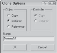
Name the clone First clone, select the Copy option, and click OK.
Click the Select and Move button (or press the W key) on the main toolbar. Then in the Top viewport, click and drag the dinosaur model to the right.
As you move the model, the original model beneath it is revealed.
Select each model in turn, and notice the name change in the Create panel's Name field. Notice that the clone is even the same object color as the original.
With the Select and Move button still active, hold down the Shift key, click the cloned dinosaur in the Top viewport, and move it to the right again. In the Clone Options dialog box that appears, select the Copy option, set the Number of Copies to 3, and click OK.
Click the Zoom Extents All button (or press Shift+Ctrl+Z) in the lower-right corner to view all the new dinosaurs.
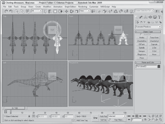
Three additional dinosaurs have appeared, equally spaced from each other. The spacing was determined by the distance that you moved the second clone before releasing the mouse. Figure 8.2 shows the results of our dinosaur cloning experiment. (Now you'll need to build a really strong fence.)
When cloning in Max, you're offered the option to create the clone as a copy, an instance, or a reference. This is true not only for objects, but for materials, modifiers, and controllers as well.
When an object is cloned, the Clone Options dialog box appears. This dialog box enables you to select to make a copy, an instance, or a reference of the original object. Each of these clone types is unique and offers different capabilities.
A copy is just what it sounds like—an exact replica of the original object. The new copy maintains no ties to the original object and is a unique object in its own right. Any changes to the copy do not affect the original object, and vice versa.
Instances are different from copies in that they maintain strong ties to the original object. All instances of an object are interconnected, so that any geometry modifications (done with modifiers or object parameters) to any single instance changes all instances. For example, if you create several instances of a mailbox and then use a modifier on one of them, all instances are also modified.
Note
Instances and references can have different object colors, materials, transformations (moving, rotating, or scaling), and object properties.
References are objects that inherit modifier changes from their parent objects, but do not affect the parent when modified. Referenced objects get all the modifiers applied to the parent and can have their own modifiers as well. For example, suppose that you have an apple object and a whole bunch of references to that apple. Applying a modifier to the base apple changes all the remaining apples, but you can also apply a modifier to any of the references without affecting the rest of the bunch.
Note
Instances and references are tied to the applied object modifiers, which are covered in more detail in Chapter 11, "Introducing Modifiers and Using the Modifier Stack."
Learning how the different clone options work will save you lots of future modifications. To investigate these options, you'll take a quick trip to the local doughnut shop.
To clone some doughnuts, follow these steps:
Create a doughnut using the Torus primitive by selecting Create
Click the torus object in the Top viewport to select it.
With the doughnut model selected, click the Select and Move button (or press the W key). Hold down the Shift key, and in the Top viewport, move the doughnut upward. In the Clone Options dialog box, select the Instance option, set the Number of Copies to 5, and click OK. Click the Zoom Extents All (or press the Shift+Ctrl+Z key) button to widen your view.
Select all objects with the Edit
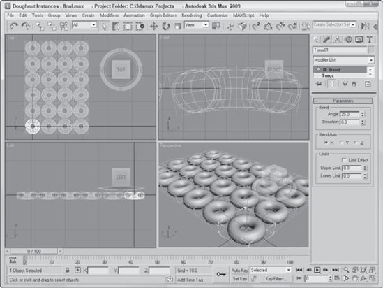
Select a single doughnut, and in the Parameters rollout of the Modify panel, set Radius1 to 20 and Radius2 to 10.
This makes a nice doughnut and changes all doughnuts at once.
Select the Modifiers
This adds a slight bend to the doughnuts.
Note
You can use modifiers to alter geometry. You can learn about using modifiers in Chapter 11, "Introducing Modifiers and Using the Modifier Stack."
Figure 8.3 shows the doughnuts all changed exactly the same. You can imagine the amount of time it would take to change each doughnut individually. Using instances made these changes easy.
Now that you have filled our bellies with doughnuts, you need some healthful food for balance. What better way to add balance than to have an apple or two to keep the doctor away?
To create some apples using referenced clones, follow these steps:
Open the Referenced Apples.max file from the Chap 08 directory on the DVD.
Select the apple, and Shift+drag with the Select and Move (W) tool in the Top viewport to create a cloned reference. Select the Reference option in the Clone Options dialog box. Then close the Clone Options dialog box.
Select the original apple again, and repeat Step 2 until several referenced apples surround the original apple.
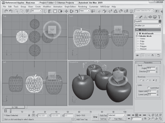
Select the original apple in the middle again, and choose the Modifiers
This smoothes all the apples.
Select one of the surrounding apples, and apply the Modifiers
Select another of the surrounding apples, and apply the Modifiers
Select another of the surrounding apples, and apply the Modifiers
Select another of the surrounding apples, and apply the Modifiers
Note
As you apply modifiers to a referenced object, notice the thick gray bar in the Modifier Stack. This bar, called the Derived Object Line, separates which modifiers get applied to all referenced objects (below the line) and which modifiers get applied to only the selected object (above the line). If you drag a modifier from above the gray bar to below the gray bar, then that modifier is applied to all references.
Using referenced objects, you can apply the major changes to similar objects, but still make minor changes to objects to make them a little different. Figure 8.4 shows the apples. Notice that they are not all exactly the same.
Have you ever held the edge of a mirror up to your face to see half of your head in the mirror? Many objects have a natural symmetry that you can exploit to require that only half an object be modeled. The human face is a good example. You can clone symmetrical parts using the Mirror command.
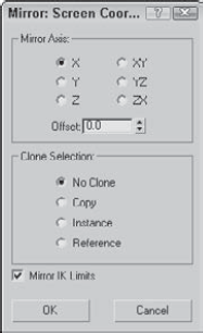
Within the Mirror dialog box, you can specify an axis or plane about which to mirror the selected object. You can also define an Offset value. As with the other clone commands, you can specify whether the clone is to be a Copy, an Instance, or a Reference, or you can choose No Clone, which flips the object around the axis you specify. The dialog box also lets you mirror IK (inverse kinematics) Limits, which reduces the number of IK parameters that need to be set.
Note
Learn more about inverse kinematics in Chapter 41, "Working with Inverse Kinematics."
Many characters have symmetry that you can use to your advantage, but to use symmetry, you can't just clone one half. Consider the position of a character's right ear relative to its right eye. If you clone the ear, then the position of each ear will be identical, with the ear to the right of the eye, which would make for a strange looking creature. What you need to use is the Mirror command, which clones the object and rotates it about a selected axis.
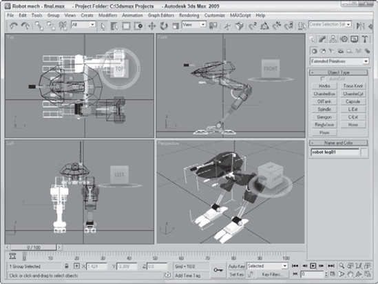
In this example, you have a complex mechanical robot with one of its legs created. Using Mirror, you can quickly clone and position its second leg.
To mirror a robot's leg, follow these steps:
Open the Robot mech.max file from the Chap 08 directory on the DVD.
This file includes a robot with one of its legs deleted.
Select all objects that make up the robot's leg in the Left viewport, and open the Mirror dialog box with the Tools
In the Mirror dialog box, select X as the Mirror Axis and Instance as the Clone Selection. Change the Offset value until the cloned leg is in position, which should be at around −2.55.
Note
The mirror axis depends on the viewport, so make sure that the Left viewport is selected.
Any changes made to the dialog box are immediately shown in the viewports.
Click OK to close the dialog box.
Note
By making the clone selection an instance, you can ensure that any future modifications to the right half of the figure are automatically applied to the left half.
Figure 8.6 shows the resulting robot—which won't be falling over now.
Another useful way to create multiple copies of an object is to have an object be created based on its position during a specific frame of an animation. This cloning at specific times is accomplished with the Snapshot feature.
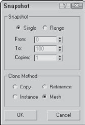
The Snapshot command creates static copies, instances, references, or even meshes of a selected object as it moves along an animation path. For example, you could create a series of footprints by animating a set of footprints moving across the screen from frame 1 to frame 100, and then choose Tools
Note
When you enter the number of Copies in the Snapshot dialog box, a copy is placed at both the beginning and end of the specified range, so if your animation path is a closed path, two objects are stacked on top of each other. For example, if you have a square animation path and you want to place a copy at each corner, you need to enter a value of 5.
Tip
The Snapshot tool can also be used with particle systems.
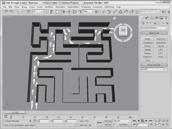
The Snapshot tool can be used to create objects as a model is moved along an animated path. In this example, you create a series of footsteps through a maze.
To create a set of footprints through a maze with the Snapshot tool, follow these steps:
Open the Path through a maze.max file from the Chap 08 directory on the DVD. This file includes a set of animated footprints that travel to the exit of a maze.
Select both footprint objects at the entrance to the maze.
Choose the Tools
Figure 8.8 shows the path of footsteps leading the way through the maze, which are easier to follow than breadcrumbs.
The Snapshot tool offers a convenient way to clone objects along an animation path, but what if you want to clone objects along a path that isn't animated? The answer is the Spacing tool. The Spacing tool can position clones at regular intervals along a path by either selecting a path and the number of cloned objects or by picking two points in the viewport.
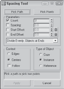
You can also specify Count, Spacing, Start Offset, and End Offset values. The drop-down list offers several preset options, including Divide Evenly, Free Center, End Offset, and more. These values and preset options are used to define the number and spacing of the objects. The spacing and position of the objects depend on the values that are included. For example, if you include only a Count value, then the objects are evenly spaced along the path including an object at each end. If an offset value is included, then the first or last item is moved away from the end by the offset value. If a Spacing value is included, then the number of objects required to meet this value is included automatically.
The Lock icons next to the Start and End Offset values force the Start or End Offset values to be the same as the Spacing value. This has the effect of pushing the objects away from their end points.
Before you can use either the Pick Path or Pick Points buttons, you must select the object to be cloned. Using the Pick Path button, you can select a spline path in the scene, and cloned objects are regularly spaced according to the values you selected. The Pick Points method lets you click to select the Start point and click again to select an end point. The cloned objects are spaced in a straight line between the two points.
The two options for determining the spacing width are Edges and Centers. The Edges option spaces objects from the edge of its bounding box to the edge of the adjacent bounding box, and the Centers option spaces objects based on their centers. The Follow option aligns the object with the path if the path is selected. Each object can be a copy, instance, or reference of the original. The text field at the bottom of the dialog box displays for your information the number of objects and the spacing value between each.
Tip
Lining up objects to correctly follow the path can be tricky. If the objects are misaligned, you can change the object's pivot point so it matches the viewport coordinates. This makes the object follow the path with correct position.
You can continue to modify the Spacing Tool dialog box's values while the dialog box is open, but the objects are not added to the scene until you click the Apply button. The Cancel button closes the dialog box.
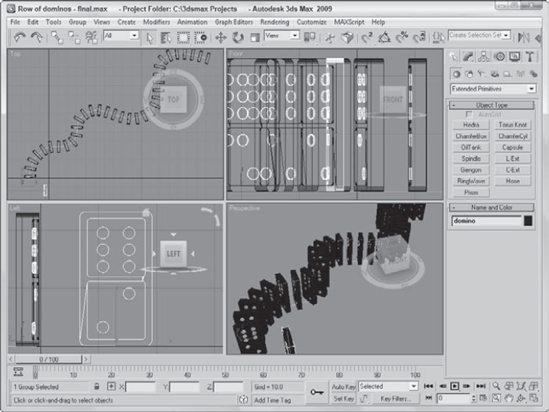
A good example of using the Spacing tool to accomplish something that is difficult in real life is to stack a row of dominoes. It is really a snap in Max, regardless of the path.
To stack a row of dominoes using the Spacing tool, follow these steps:
Open the Row of dominoes.max file from the Chap 08 directory on the DVD.
This file includes a single domino and a wavy spline path.
Select the domino object, and open the Spacing tool by selecting the flyout button under the Array button on the Extras toolbar (or by pressing Shift+I).
In the Spacing Tool dialog box, click the Pick Path button and select the wavy path.
The path name appears on the Pick Path button.
From the drop-down list in the Parameters section of the Spacing Tool dialog box, select the Count option with a value of 35.
This is the same as the Divide Evenly, Objects at Ends option in the drop-down list.
Select the Edges context option, check the Follow check box, and make all clones Instances. Click Apply when the result looks right, and close the Spacing Tool dialog box.
Figure 8.10 shows the simple results. The Spacing Tool dialog box remains open until you click the Cancel button.
Imagine you're working on a production team and the modeler assigned to the project says he needs some more time to make the building columns "something special." Just as you prepare to give him the "deadlines don't die" speech, you remember the Clone and Align tool. Using this tool, you can place proxy objects where the detailed ones are supposed to go. Then, when the detailed object is ready, the Clone and Align tool lets you clone the detailed object and place it where all the proxies are positioned. This, of course, makes the modeler happy and doesn't disrupt your workflow. Another production team victory.
Before selecting the Tools
Note
The Align tool is covered in Chapter 7, "Transforming Objects, Pivoting, Aligning, and Snapping."
The Clone and Align dialog box also lets you select whether source objects are cloned as copies, instances, or references. In the Align Parameters rollout, you can specify the object's position and orientation using the same controls that are used to align objects, including any Offset values.
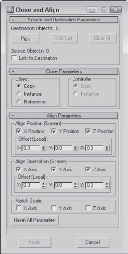
Figure 8.11. The Clone and Align dialog box lets you choose which objects mark the place where the source object should go.
As you make changes in the Clone and Align dialog box, the objects are updated in the viewports, but these changes don't become permanent until you click the Apply button. The Clone and Align dialog box is persistent, meaning that, after being applied, the settings remain until they are changed.
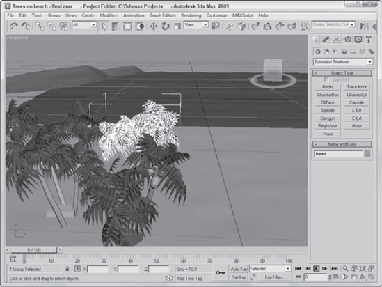
To practice using the Clone and Align tool, you'll open a beach scene with a single set of grouped trees. Several other box objects have been positioned and rotated about the scene. The trees will be the source object and the box objects will be the destinations.
To position and orient several high-res trees using the Clone and Align tool, follow these steps:
Open the Trees on beach.max file from the Chap 08 directory on the DVD.
This file includes a beach scene created by Viewpoint Datalabs.
Select the tree objects that have been grouped together, and open the Clone and Align dialog box by selecting the Tools
In the Clone and Align dialog box, click the Pick button and select each of the box objects in the scene.
In the Align Parameters rollout, enable the X and Y axes for the Positions and the X, Y, and Z axes for the Orientation. Then click the Apply button.
Figure 8.12 shows the simple results. Notice that the destination objects have not been replaced and are still there.
Now that you've probably figured out how to create arrays of objects by hand with the Shift-clone method, the Array command multiplies the fun by making it easy to create many copies instantaneously. The Array dialog box lets you specify the array dimensions, offsets, and transformation values. These parameters enable you to create an array of objects easily.
The Array dialog box is also persistent. You can reset all the values at once by clicking the Reset All Parameters button. You can also preview the current array settings without actually creating an array of objects using the Preview button. The Display as Box option lets you see the array as a bounding box to give you an idea of how large the array will be.
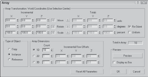
Figure 8.13. The Array dialog box defines the number of elements and transformation offsets in an array.
Linear arrays are arrays in which the objects form straight lines, such as rows and columns. Using the Array dialog box, you can specify an offset along the X-, Y-, and Z-axes at the top of the dialog box and define this offset as an incremental amount or as a total amount. To change between incremental values and total values, click the arrows to the left and right of the Move, Rotate, and Scale labels. For example, an array with 10 elements and an incremental value of 5 will position each successive object a distance of 5 units from the previous one. An array with 10 elements and a total value of 100 will position each element a distance of 10 units apart by dividing the total value by the number of clones.
The Move row values represent units as specified in the Units Setup dialog box. The Rotate row values represent degrees, and the Scale row values are a percentage of the selected object. All values can be either positive or negative values.
Clicking the Re-Orient check box causes the coordinate system to be reoriented after each rotation is made. If this check box isn't enabled, then the objects in the array do not successively rotate. Clicking the Uniform check box to the right of the Scale row values disables the Y and Z Scale value columns and forces the scaling transformations to be uniform. To perform non-uniform scaling, simply deselect the Uniform check box.
The Type of Object section lets you define whether the new objects are copies, instances, or references, but unlike the other cloning tools, the Array tool defaults to Instance. If you plan on modeling all the objects in a similar manner, then you will want to select the Instance or Reference options.
In the Array Dimensions section, you can specify the number of objects to copy along three different dimensions. You can also define incremental offsets for each individual row.
Warning
You can use the Array dialog box to create a large number of objects. If your array of objects is too large, your system may crash.
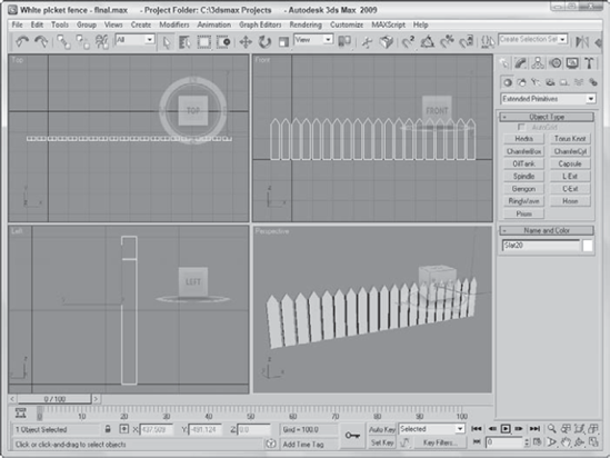
To start with a simple example, you'll create a white picket fence. Because a fence repeats, you need only to create a single slat; then you'll use the Array command to duplicate it consistently.
To create a picket fence, follow these steps:
Open the White picket fence.max file from the Chap 08 directory on the DVD.
With the single fence board selected, choose Tools
In the Array dialog box, click the Reset All Parameters button to start with a clean slate. Then enter a value of 50 in the X column's Move row under the Incremental section. (This is the incremental value for spacing each successive picket.) Next, enter 20 in the Array Dimensions section next to the 1D radio button. (This is the number of objects to include in the array.) Click OK to create the objects.
Tip
The Preview button lets you see the resulting array before it is created. Don't worry if you don't get the values right the first time. The most recent values you entered into the Array dialog box stay around until you exit Max.
Click the Zoom Extents All button (or press Shift+Ctrl+Z) in the lower-right corner of the Max window to see the entire fence in the viewports.
Figure 8.14 shows the completed fence.
Note
For more about how these settings affect transformations, see Chapter 7, "Transforming Objects, Pivoting, Aligning, and Snapping."
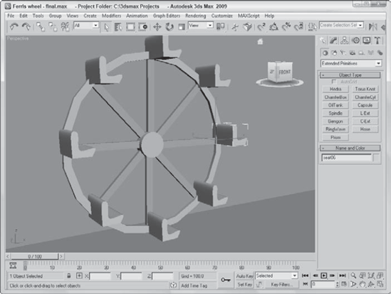
Ferris wheels, like most of the rides at the fair, entertain by going around and around, with the riders seated in chairs spaced around the Ferris wheel's central point. The Array dialog box can also create objects around a central point.
To create a circular array, follow these steps:
Open the Ferris wheel.max file from the Chap 08 directory on the DVD.
This file has the Front viewport maximized to show the profile of the Ferris wheel.
Click the Use Pivot Point Center button on the main toolbar, and drag down to the last icon, which is the Use Transform Coordinate Center button.
The Use Transform Coordinate Center button becomes active. This button causes all transformations to take place about the axis in the center of the screen.
Select the light blue chair object, and open the Array dialog box by choosing Tools
Between the Incremental and Totals sections are the labels Move, Rotate, and Scale. Click the arrow button to the right of the Rotate label. Set the Z column value of the Rotate row to 360 degrees, and make sure that the Re-Orient option is disabled.
A value of 360 degrees defines one complete revolution. Disabling the Re-Orient option keeps each chair object from gradually turning upside down.
In the Array Dimensions section, set the 1D spinner Count value to 8 and click OK to create the array.
Next select the green strut, and open the Array dialog box again with the Tools
Figure 8.15 shows the resulting Ferris wheel. You can click the Min/Max toggle in the lower-right corner to view all four viewports again.
You can find the Ring Array system by opening the Create panel and selecting the Systems category. Clicking the Ring Array button opens a Parameters rollout. In this rollout are parameters for the ring's Radius, Amplitude, Cycles, Phase, and the Number of elements to include.
You create the actual array by clicking and dragging in one of the viewports. Initially, all elements are simple box objects surrounding a green dummy object.
The Amplitude, Cycles, and Phase values define the sinusoidal nature of the circle. The Amplitude is the maximum distance that you can position the objects from the horizontal plane. If the Amplitude is set to 0, then all objects lie in the same horizontal plane. The Cycles value is the number of waves that occur around the entire circle. The Phase determines which position along the circle starts in the up position.
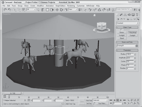
Continuing with the theme park attractions motif, this example creates a carousel. The horse model comes from Poser but was simplified using the MultiRes modifier.
To use a Ring Array system to create a carousel, follow these steps:
Open the Carousel.max file from the Chap 08 directory on the DVD.
This file includes a carousel structure made from primitives along with a carousel horse.
Open the Create panel, select the Systems category, and click the Ring Array button. Drag in the Top viewport from the center of the carousel to create a ring array. Then enter a Radius value of 250, an Amplitude of 20, a Cycles value of 3, and a Number value of 6. Then right-click in the active viewport to deselect the Ring Array tool.
Note
If the Ring Array object gets deselected, you can access its parameters in the Motion panel, not in the Modify panel.
Select the Ring Array's Dummy object in the Left viewport, select the Tools
Select the horse object, and choose the Tools
Figure 8.16 shows the finished carousel. Notice that each horse is at a different height. Once the horses are placed, you can delete or hide the ring array object.
Many ways to clone an object are available. You can use the Clone command under the Edit menu or the Shift-clone feature for quickly creating numerous clones. Clones can be copies, instances, or references. Each differs in how it retains links to the original object. You can also clone using the Mirror, Snapshot, and Spacing tools.
Arrays are another means of cloning. You can use the Array dialog box to produce clones in three different dimensions, and you can specify the offset transformations.
This chapter covered the following cloning topics:
Cloning objects and Shift-cloning
Understanding copies, instances, and references
Using the Mirror, Snapshot, Spacing, and Clone and Align tools
Building linear, circular, and spiral arrays of objects
Using the Ring Array system
In the next chapter, you learn to group objects and link them into hierarchies. Then you'll be able to organize into structures all the objects that you've learned to create.