
Now that you've learned how to select and clone objects, you'll want to learn how to group objects in an easily accessible form, especially as a scene becomes more complex. Max's grouping features enable you to organize all the objects that you're dealing with, thereby making your workflow more efficient.
Another way of organizing objects is to build a linked hierarchy. A linked hierarchy attaches, or links, one object to another and makes it possible to transform the attached object by moving the object to which it is linked. The arm is a classic example of a linked hierarchy: When the shoulder rotates, so do the elbow, wrist, and fingers. Establishing linked hierarchies can make moving, positioning, and animating many objects easy.
Grouping objects organizes them and makes them easier to select and transform. Groups are different from selection sets in that groups exist like one object. Selecting any object in the group selects the entire group, whereas selecting an object in a selection set selects only that object and not the selection set. You can open groups to add, delete, or reposition objects within the group. Groups can also contain other groups. This is called nesting groups.
The Group command enables you to create a group. To do so, simply select the desired objects and choose Group
The Ungroup command enables you to break up a group (kind of like a poor music album). To do so, simply select the desired group and choose Group
Warning
If you animate a group and then later use the ungroup command, then all the keys created for the whole group are lost when you ungroup.
The easiest way to dissolve an entire group, including any nested groups, is with the Explode command. This command eliminates the group and the groups within the group and makes each object separate.
The Open command enables you to access the objects within a group. Grouped objects move, scale, and rotate as a unit when transformed, but individual objects within a group can be transformed independently after you open a group with the Open command.
To move an individual object in a group, select the group and choose Group
The Attach and Detach commands enable you to insert or remove objects from an opened group without dissolving the group. To attach objects to an existing group, you select an object, select the Attach menu command, and then click on the group to which you want to add the object. To detach an object from a group, you need to open the group and select the Detach menu command. Remember to close the group when finished.
Note
Editable objects, like the Editable Poly, also can make use of an Attach feature, but attaching objects to an editable object permanently combines the objects together. You can learn more about the Editable Poly objects in Chapter 13, "Modeling with Polygons."
Positioning objects relative to one another takes careful and precise work. After spending the time to place the wings, tail, and prop on a plane exactly where they need to be, transforming each object by itself can misalign all the parts. By grouping all the objects together, you can move all the objects at once.
For this tutorial, you can get some practice grouping all the parts of an airplane together. Follow these steps:
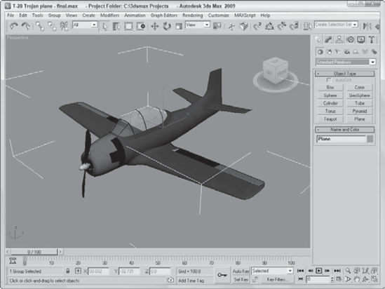
Open the T-28 Trojan plane.max file from the Chap 09 directory on the DVD. This file includes a model created by Viewpoint Datalabs.
Click the Select by Name button on the main toolbar (or press the H key) to open the Select from Scene dialog box. In this dialog box, notice all the different plane parts. Click the Select All button to select all the separate objects, and click OK to close the dialog box.
With all the objects selected, choose Group

Click the Select and Move button (or press W), and click and drag the plane.
The entire group now moves together.
Figure 9.1 shows the plane grouped as one unit. Notice how only one set of brackets surrounds the plane in the Perspective viewport. The group name is displayed in the Name field of the Command Panel instead of listing the number of objects selected.
At the bottom of the Group menu is a menu item called Assembly with a submenu that looks frightfully similar to the Group menu. The difference between a group and an assembly is that an assembly can include a light object with a Luminaire helper object as its head. This enables you to build light fixtures where the light is actually grouped (or assembled) with the light stand objects. Once built, you can control the light by selecting and moving the light assembly.
After you've created the geometry for a light assembly, you can create an assembly with the Group
Luminaire objects can be confusing because they don't actually add light to an assembly. If you're curious about the Luminaire objects, you can find them in the Assembly Heads subcategory of the Helper category.
The benefit of the Luminaire helper object is that it can add to an assembly some simple parameters that are accessible whenever the assembly is selected. These parameters work only if you wire them to the parameters of the light object included in the assembly.
Note
You can learn more about wiring parameters in Chapter 20, "Understanding Animation and Keyframe Basics."
To wire Luminaire parameters to the light object's parameters, select the assembly and open the Parameter Wiring dialog box with the Animation
After the assembly light is wired to the Luminaire parameters, you can use the Dimmer and Filter Color parameters in the Modify panel whenever the assembly is selected.
Max uses several terms to describe the relationships between objects. A parent object is an object that controls any secondary, or child, objects linked to it. A child object is an object that is linked to and controlled by a parent. A parent object can have many children, but a child can have only one parent. Additionally, an object can be both a parent and a child at the same time. Another way to say this is:
Child objects are linked to parent objects.
Moving a parent object moves its children with it.
Child objects can move independently of their parents.
A hierarchy is the complete set of linked objects that includes these types of relationships. Ancestors are all the parents above a child object. Descendants are all the children below a parent object. The root object is the top parent object that has no parent and controls the entire hierarchy.
Each hierarchy can have several branches or subtrees. Any parent with two or more children represents the start of a new branch.
Note
The default hierarchies established using the Link tool are referred to as forward-kinematics systems, in which control moves forward down the hierarchy from parent to child. In forward-kinematics systems, the child has no control over the parent. An inverse kinematics system (covered in Chapter 41, "Working with Inverse Kinematics") enables child objects to control their parents.
All objects in a scene, whether linked or not, belong to a hierarchy. Objects that aren't linked to any other objects are, by default, children of the world object, which is an imaginary object that holds all objects.
Note
You can view the world object, labeled Objects, in the Track View. Individual objects are listed under the Objects track by their object name.
You have several ways to establish hierarchies using Max. The simplest method is to use the Link and Unlink buttons found on the main toolbar. You can also find these buttons in the Schematic View window. The Hierarchy panel in the Command Panel provides access to valuable controls and information about established hierarchies. When creating complex hierarchies, a bones system can help.
Note
The Schematic View window is covered in Chapter 24, "Working with the Schematic View," and bone systems are covered in Chapter 40, "Understanding Rigging and Working with Bones."
The main toolbar includes two buttons that you can use to build a hierarchy: Link and Unlink. The order of selection defines which object becomes the parent and which becomes the child.
To link two objects, click the Link button. This places you in Link mode, which continues until you turn it off by selecting another button, such as the Select button or one of the Transform buttons. When you're in Link mode, the Link button is highlighted dark yellow.
With the Link button highlighted, click an object, which will be the child, and drag a line to the target parent object. The cursor arrow changes to the link icon when it is over a potential parent. When you release the mouse button, the parent object flashes once and the link is established. If you drag the same child object to a different parent, the link to the previous parent is replaced by the link to the new parent.
Once linked, all transformations applied to the parent are applied equally to its children about the parent's pivot point. A pivot point is the center about which the object rotates.
To eliminate all links for an entire hierarchy, double-click an object to select its entire hierarchy and click the Unlink button.
What better way to show off parent-child relationships than with a family? I could have modeled my own family, but for some reason, my little ducks don't always like to follow me around.
To create a linked family of ducks, follow these steps:
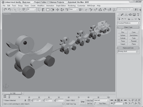
Open the Linked duck family.max file from the Chap 09 directory on the DVD. This file includes several simple ducks lined up in a row.
Click the Select and Link button in the main toolbar, and drag a line from the last duck to the one just in front of it.
Continue to connect each duck to the one in front of it.
Click the Select and Move button (or press the W key), and move the Mommy duck. Notice how all the children move with her.
Figure 9.2 shows the duck family as they move forward in a line. The Link button made it possible to move all the ducks simply by moving the parent duck.
The Display panel includes a rollout that lets you display all the links in the viewports.
After links have been established, you can see linked objects listed as a hierarchy in several places. The Select Objects dialog box, opened with the Select by Name button (or with the H key), can display objects in this manner, as well as the Schematic and Track Views.
You can choose to see the links between the selected objects in the viewports by selecting the Display Links option in the Link Display rollout of the Display panel. The Display Links option shows links as lines that run between the pivot points of the objects with a diamond-shaped marker at the end of each line; these lines and markers are the same color as the object.
Note
The Display Links option can be enabled or disabled for each object in the scene. To display the links for all objects, use the Edit
The Link Display rollout also offers the Link Replaces Object option, which removes the objects and displays only the link structure. This feature removes the complexity of the objects from the viewports and lets you work with the links directly. Although the objects disappear, you can still transform the objects using the link markers.
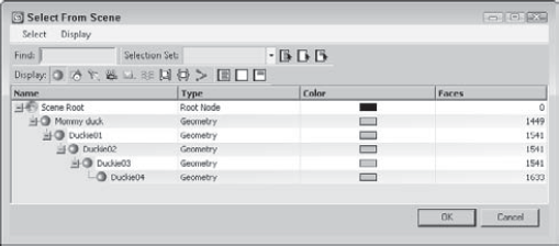
The Select From Scene dialog box (also called the Scene Explorer) and the Schematic and Track Views can display the hierarchy of objects in a scene as an ordered list, with child objects indented under parent objects.
Clicking the Select by Name button (H) on the main toolbar opens the Scene Explorer dialog box; select the Display
Note
You can learn more about the Scene Explorer in Chapter 6, "Selecting Objects, Setting Object Properties, and Using Layers and the Scene Explorer."
The Schematic View (opened with the Graph Editors
Note
For more information on using the Schematic View, see Chapter 24, "Working with the Schematic View."
The Track View (opened with the Graph Editors
Note
For more information on using the Track View, see Chapter 34, "Working with Function Curves in the Track View."
If you link some objects together and set some animation keys, and the magical Play button starts sending objects hurtling off into space, chances are good that you have a linked object that you didn't know about. Understanding object hierarchies and being able to transform those hierarchies are the keys to efficient animation sequences.
All transformations are done about an object's pivot point. You can move and reorient these pivot points as needed by clicking the Pivot button under the Hierarchy panel.
Several additional settings for controlling links are available under the Hierarchy panel of the Command Panel (the Hierarchy panel tab looks like a mini-organizational chart). Just click the Link Info button. This button opens two rollouts if a linked object is selected. You can use the Locks and Inherit rollouts to limit an object's transformations and specify the transformations that it inherits.
Note
I present more information on object transformations in Chapter 7, "Transforming Objects, Pivoting, Aligning, and Snapping."
The Inherit rollout, like the Locks rollout, includes check boxes for each axis and each transformation, except that here, all the transformations are selected by default. By deselecting a check box, you specify which transformations an object does not inherit from its parent. The Inherit rollout appears only if the selected object is part of a hierarchy.
For example, suppose that a child object is created and linked to a parent and the X Move Inherit check box is deselected. As the parent is moved in the Y or Z directions, the child follows, but if the parent is moved in the X direction, the child does not follow. If a parent doesn't inherit a transformation, then its children don't either.
The Link Inheritance utility works in the same way as the Inherit rollout of the Hierarchy panel, except that you can apply it to multiple objects at the same time. To use this utility, open the Utility panel and click the More button. In the Utilities dialog box, select the Link Inheritance utility and click OK. The rollout for this utility is identical to the Inherit rollout discussed in the previous section.
You need to select a hierarchy before you can transform it, and you have several ways to do so. The easiest method is to simply double-click an object. Double-clicking the root object selects the entire hierarchy, and double-clicking an object within the hierarchy selects it and all of its children.
After you select an object in a hierarchy, pressing the Page Up or Page Down keyboard shortcut selects its parent or child objects. For example, if you select the Mommy duck object and press Page Down, the first baby duck object is selected and the Mommy duck object is deselected. Selecting any of the baby duck objects and pressing Page Up selects the duck object in front of it.
Dummy objects are useful as root objects for controlling the motion of hierarchies. By linking the parent object of a hierarchy to a dummy object, you can control all the objects by moving the dummy.
To create a dummy object, select Create
When you work with complex models with lots of parts, you can control the object more easily if you link it to a Dummy object and then animate the dummy object instead of the entire model. To practice doing this, you'll create a simple animation of an airplane flying around the globe. To perform this feat, you create a dummy object in the center of a sphere, link the airplane model to it, and rotate the dummy object. This tutorial involves transforming and animating objects, which are covered in other chapters.
Note
Rotating objects is covered in Chapter 7, "Transforming Objects, Pivoting, Aligning, and Snapping," and the basics of animation are covered in Chapter 20, "Understanding Animation and Keyframe Basics."
To link and rotate objects using a dummy object, follow these steps:
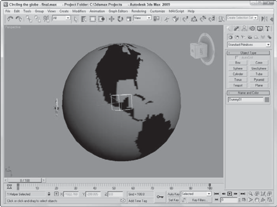
Open the Circling the globe.max file found in the Chap 09 directory on the DVD.
This file includes a texture mapped sphere with an airplane model positioned above it. The airplane model was created by Viewpoint Datalabs.
Select Create
Because the dummy object is inside the sphere, creating the link between the airplane and the dummy object can be difficult. To simplify this process, select and right-click the sphere object, and then select Hide Selection from the pop-up menu.
This hides the sphere so that you can create a link between the airplane and the dummy object.
Click the Select and Link button on the main toolbar, and drag a line from the airplane to the dummy object.
Click the Auto Key button (or press N) to enable animation key mode, and drag the Time Slider to frame 100. Then click the Select and Rotate button on the main toolbar (or press E), and select the dummy object. Then rotate the dummy object about its X-axis, and notice how the linked airplane also rotates over the surface of the sphere.
Select the dummy object and right-click to access the pop-up quadmenu. Then select the Unhide All menu command to make the sphere visible again.
By linking the airplane to a dummy object, you don't have to worry about moving the airplane's pivot point to get the correct motion. Figure 9.4 shows a frame from the final scene.
As scenes become more complex, the name of the game is organization. You can organize objects within the scene in several ways, including grouping, linking, and building hierarchies.
In this chapter, you've done the following:
Grouped objects using the Group menu and learned to work with groups
Learned about parent, child, and root relationships
Created a hierarchy of objects using the Link and Unlink features
Viewed links in the viewport
Learned how to create and use dummy objects
In the next chapter, you jump headfirst into modeling by covering the basics of modeling and working with subobjects and helper objects.