
Meshes (or, more specifically, polygon meshes) are perhaps the most popular and the default model type for most 3D programs. You create them by placing polygonal faces next to one another so the edges are joined. The polygons can then be smoothed from face to face during the rendering process. Using meshes, you can create almost any 3D object, including simple primitives such as a cube or a realistic dinosaur.
Meshes have lots of advantages. They are common, intuitive to work with, and supported by a large number of 3D software packages. In this chapter, you learn how to create and edit mesh and poly objects.
Before continuing, you need to understand exactly what a Poly object is, how it differs from a regular mesh object, and why it is the featured modeling type in Max. To understand these issues, you'll need a quick history lesson. Initially, Max supported only mesh objects and all mesh objects had to be broken down into triangular faces. Subdividing the mesh into triangular faces ensured that all faces in the mesh object were coplanar, which prevented any hiccups with the rendering engine.
Over time, the rendering engines have been modified and upgraded to handle polygons that weren't subdivided (or whose subdivision was invisible to the user), and doing such actually makes the model more efficient by eliminating all the extra edges required to triangulate the mesh. Also, users can work with polygon objects more easily than individual faces. To take advantage of these new features, the Editable Poly object was added to Max.
As development has continued, many new features have been added to the Editable Poly object while the Editable Mesh remained mainly for backwards compatibility. The one advantage that the Editable Mesh object had over the Editable Poly was that the Edit Mesh modifier could be applied, but as of version 7, Max has an Edit Poly modifier, which lets you make changes to an object as a modifier that can easily be removed.
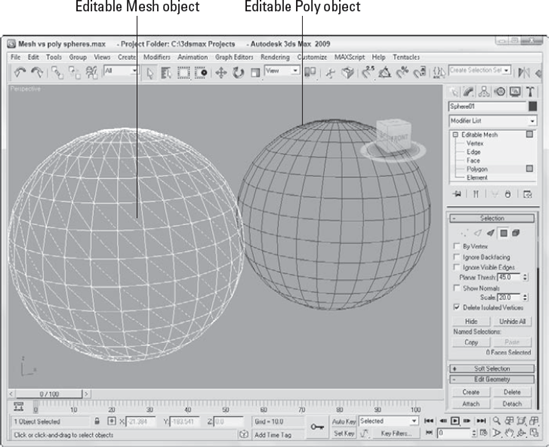
Even with the addition of the Edit Poly modifier, the Editable Mesh object type still exists, and there are times when you'll want to use each type, shown in Figure 13.1. Editable Mesh objects split all polygons into triangular faces, but the Editable Poly object maintains four-sided (or more) polygon faces. Another key difference is found in the subobjects. Editable Meshes can work with Vertex, Edge, Face, Polygon, and Element subobjects; and Editable Poly objects can work with Vertex, Edge, Border, Polygon, and Element subobjects.
Some game engines still require that all faces be coplanar, and for such conditions you'll want to continue to use the Editable Mesh object. Another case where the Editable Mesh object is helpful is in performing certain face-oriented operations. In addition, normal meshes have a smaller memory footprint, which enables them to render more quickly, especially if you have many of them. Regardless, Max lets you convert seamlessly between these two modeling types.
Although many of the same features are available for both object types, the advance features available for the Editable Poly object make it the preferred object type to use for mesh modeling. This chapter focuses on working with Editable Poly objects. Although the specific features of the Editable Mesh object aren't covered, most of these same commands apply equally to the Editable Mesh object.
The Create panel has no method for making mesh objects—mesh objects must be converted from another object type or produced as the result of a modifier. Object types that you can convert include shapes, primitives, Booleans, patches, and NURBS. Many models that are imported appear as mesh objects. Most 3D formats, including 3DS and DXF, import as mesh objects.
Note
You can even convert spline shapes to editable poly objects, whether they are open or closed. Closed splines are filled with a polygon, whereas open splines are only a single edge and can be hard to see.
Before you can use many of the mesh editing functions discussed in this chapter, you need to convert the object to an Editable Poly object, collapse an object with modifiers applied, or apply the Edit Poly modifier.
To convert an object into an Editable Poly object, right-click the object and choose Convert To
When an object is collapsed, it loses its parametric nature and the parameters associated with any applied modifiers. Only objects that have had modifiers applied to them can be collapsed. Objects are made into an Editable Poly object when you use the Collapse To option available from the right-click pop-up menu in the Modifier Stack or when you use the Collapse utility.
Tip
You can also collapse objects using the Collapse utility found in the Utilities panel.
Most objects collapse to Editable Poly objects, but some objects, such as the compound objects, give you an option of which structure to collapse to.
Another way to enable the mesh editing features is to apply the Edit Poly modifier to an object. You apply this modifier by selecting the object and choosing Modifiers
The Edit Poly modifier is different from the Editable Poly object in that, as an applied modifier, it maintains the parametric nature of the original object. For example, you cannot change the Radius value of a sphere object that has been converted to an Editable Poly, but you could if the Edit Poly modifier were applied.
After an object has been converted to an Editable Poly, you can alter its shape by applying modifiers, or you can work with the mesh subobjects. You can find the editing features for these objects in the Modify panel.
Note
Each of the mesh related modifiers is covered in Chapter 25, "Deforming Surfaces and Using the Mesh Modifiers."
Before you can edit poly subobjects, you must select them. To select a subobject mode, select Editable Poly in the Modifier Stack, click the small plus sign to its left to display a hierarchy of subobjects, and then click the subobject type with which you want to work. Another way to select a subobject type is to click on the appropriate subobject button in the Selection rollout. The subobject button in the Selection rollout and the subobject listed in the Modifier Stack both turn bright yellow when selected. You can also type a number from 1 to 5 to enter subobject mode with 1 for Vertex, 2 for Edge, 3 for Border, 4 for Polygon, and 5 for Element.
The Vertex subobject mode lets you select and work with all vertices in the object. Edge subobject mode makes all edges that run between two vertices available for selection. The Border subobject mode lets you select all edges that run around an opening in the object such as a hole. The Polygon subobject mode lets you work with individual polygon faces and the Element subobject mode picks individual objects if the object includes several different elements.
To exit subobject edit mode, click the subobject button (displayed in yellow) again. Remember, you must exit this mode before you can select another object.
Note
Selected subobject edges appear in the viewports in red to distinguish them from edges of the selected object, which appear white when displayed as wireframes.
After you're in a subobject mode, you can click on a subobject (or drag over an area to select multiple subobjects) to select it and edit the subobject using the transformation buttons on the main toolbar. You can transform subobjects just like other objects.
Note
For more information on transforming objects, see Chapter 7, "Transforming Objects, Pivoting, Aligning, and Snapping."
When working with Editable Poly objects in subobject mode, you can use Press and Release keyboard shortcuts. These shortcuts are identified in bold in the Editable Poly group of the Keyboard panel of the Customize User Interface dialog box. When using these keyboard shortcuts, you can access a different editing mode without having to exit subobject mode. For example, if you press and hold Alt+C while in Polygon subobject mode, you can make a cut with the Cut tool and when you release the keyboard keys, you'll return to Polygon subobject mode.
Note
You can learn more about the Customize User Interface dialog box in Chapter 4, "Customizing the Max Interface and Setting Preferences."
You can select multiple subobjects at the same time by dragging an outline over them. You can also select multiple subobjects by holding down the Ctrl key while clicking them. The Ctrl key can also deselect selected subobjects while maintaining the rest of the selection. Holding down the Alt key removes any selected vertices from the current selection set.
With one of the transform buttons selected, hold down the Shift key while clicking and dragging on a subobject to clone it. During cloning, the Clone Part of Mesh dialog box appears, enabling you to Clone to Object or Clone to Element. Using the Clone to Object option makes the selection an entirely new object, and you are able to give the new object a name. If the Clone to Element option is selected, the clone remains part of the existing object but is a new element within that object.
If you hold down the Ctrl key while choosing a different subobject mode, the current selection is maintained for the new subobject type. For example, if you select all the polygons in the top half of a model using the Polygon subobject mode and click the Vertex subobject mode while holding down the Ctrl key, all vertices in the top half of the model are selected. This works only for the applicable subobjects. If the selection of polygons doesn't have any borders, then holding down the Ctrl key while clicking the Border subobject mode selects nothing.
You also can hold down the Shift key to select only those subobjects that lie on the borders of the current selection. For example, selecting all the polygons in the top half of a model using the Polygon subobject mode and clicking the Vertex subobject mode with the Shift key held down selects only those vertices that surround the selection and not the interior vertices.
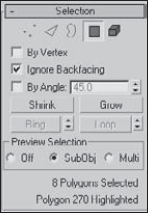
The Selection rollout, shown in Figure 13.2, includes options for selecting subobjects. The By Vertex option is available in all but the Vertex subobject mode. It requires that you click a vertex in order to select an edge, border, polygon, or element. It selects all edges and borders that are connected to a vertex when the vertex is selected. The Ignore Backfacing option selects only those subobjects with normals pointing toward the current viewport. For example, if you are trying to select some faces on a sphere, only the faces on the side closest to you are selected. If this option is off, then faces on both sides of the sphere are selected. This option is helpful if many subobjects are on top of one another in the viewport.
Tip
The select commands in the Edit menu also work with subobjects. For example, in Vertex subobject mode, you can select Edit
The By Angle option selects adjacent polygons that are within the specified threshold. The threshold value is defined as the angle between the normals of adjacent polygons. For example, if you have a terrain mesh with a smooth, flat lake area in its middle, you can select the entire lake area if you set the Planar Threshold to 0 and click the lake.
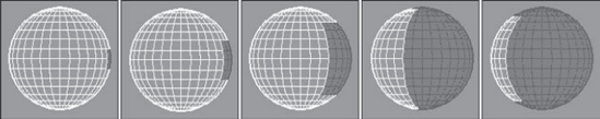
The Selection rollout also includes four buttons. These buttons include Shrink, Grow, Ring, and Loop. Use the Grow button to increase the current selection around the perimeter of the current selection, as shown in Figure 13.3. Click the Shrink button to do the opposite.
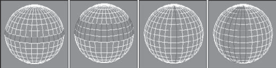
The Ring and Loop buttons are available only in Edge and Border subobject modes. Use Ring and Loop to select all adjacent subobjects horizontally and vertically around the entire object. Ring selection looks for parallel edges, and Loop selection looks for all edges around an object that are aligned the same as the initial selection. For example, if you select a single edge of a sphere, the Ring button selects all edges going around the sphere and the Loop button selects all edges in a line from the top to the bottom of the sphere.
Next to the Ring and Loop buttons is a set of up/down arrows. These arrows are used to shift the current ring and/or loop selection left and right for the Ring selection, or up and down for the Loop selection. Holding down the Ctrl key adds the adjacent ring or loop to the current selection, and holding down the Alt key removes the adjacent selection. Figure 13.4 shows how the Ring and Loop buttons work. The first sphere shows a selection made using the Ring button; the second sphere has increased this selection by holding down the Ctrl key while clicking the up arrow next to the Loop button. The third sphere shows a selection made using the Loop button; the fourth sphere has increased this selection by holding down the Ctrl key while clicking the up arrow next to the Ring button.
Note
For Editable Poly objects, the Hide Selected, Unhide All, Copy, and Paste buttons are located at the bottom of the Edit Geometry rollout.
Note
The Soft Selection rollout allows you to alter adjacent non-selected subobjects when selected subobjects are moved, creating a smooth transition. For the details on this rollout, see Chapter 10, "Learning Modeling Basics and Working with Subobjects and Helpers."
The Preview Selection options let you quickly move among the different subobject modes by selecting the highlighted subobject in the viewports. When the SubObj preview option is enabled, the subobjects for the current mode are highlighted as you move the cursor over the object. For example, if you have Polygon subobject mode selected and the SubObj preview option enabled, moving the mouse cursor over the top of each polygon automatically highlights the polygon that the cursor is over. This provides vital feedback for ensuring that you are selecting the correct subobject.
Also while this preview mode is on, you can highlight multiple subobjects by holding down the Ctrl key while you move the mouse over the top of the object. This gives you an easy way to paint a selection. If you click when multiple subobjects are highlighted, then all the highlighted subobjects are selected.
Even if you like the SubObj previewing option, the Multi previewing option is even better, allowing Vertex, Edge, and Polygon subobjects to be highlighted as you move the cursor about. If you're in Polygon subobject mode and you select the highlighted edge subobject, Max automatically switches to Edge subobject mode. This previewing option lets you select any kind of subobject without having to switch to the different subobject modes using the Command Panel or a keyboard shortcut.
Holding down the Ctrl key locks you into the current subobject and lets you paint to highlight multiple subobjects.
Note
The space at the very bottom of the Selection rollout shows the number of subobjects currently selected or the number of the single selected subobject. It also lists the specific subobject that is highlighted.
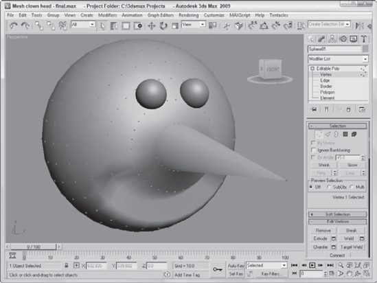
Now that you know how to select subobjects, you can use the transform tools to move them. In this example, you'll quickly deform a sphere to create a clown face by selecting, moving, and working with some vertices.
To create a clown head by moving vertices, follow these steps:
Select Create

Open the Modify panel. Now make a long, pointy nose by pulling a vertex outward from the sphere object. Click the small plus sign to the left of the Editable Poly object in the Modifier Stack, and select Vertex in the hierarchy (or press the 1 key). This activates the Vertex subobject mode. Enable the Ignore Backfacing option in the Selection rollout, and select the single vertex in the center of the Front viewport. Make sure that the Select and Move button (W) is selected, and in the Left viewport, drag the vertex along the Z-axis until it projects from the sphere.
Next, create the mouth by selecting and indenting a row of vertices in the Front viewport below the protruding nose. Holding down the Ctrl key makes selecting multiple vertices easy. Below the nose, select several vertices in a circular arc that make a smile. Then move the selected vertices along the negative Z-axis in the Left viewport.
For the eyes, select Create
This clown head is just a simple example of what is possible by editing subobjects. Figure 13.5 shows the clown head in a shaded view.
Much of the power of editing meshes is contained within the Edit Geometry rollout, shown in Figure 13.6. Features contained here include, among many others, the ability to create new subobjects, attach subobjects to the mesh, weld vertices, chamfer vertices, slice, explode, and align. Some Edit Geometry buttons are disabled depending on the subobject mode that you select. The features detailed in this section are enabled for the Editable Poly object before you enter a subobject mode.
Many of the buttons for the Editable Poly include a small icon to the right of the button that opens a settings dialog box. These settings dialog boxes allow you to change the settings and immediately see the results in the viewports. The OK button applies the settings and closes the dialog box, and the Apply button applies the settings and leaves the dialog box open. These settings dialog boxes are included next to the Preserve UVs, Attach, MSmooth, Tessellate, and Relax buttons for all subobject modes and next to many of the subobject-specific buttons such as Extrude, Bevel, Outline, and Inset.
Editable Poly objects include all their common buttons in the Edit Geometry rollout and all subobject-specific buttons is a separate rollout named after the subobject mode, such as Edit Vertices or Edit Edges.
The first button in the Edit Geometry rollout is the Repeat Last button. This button repeats the last subobject command. This button does not work on all features, but it's very convenient for certain actions.
Tip
The tooltip for this button displays the last repeatable command.
The Constraints options limit the movement of subobjects to a specified subobject. The available constraints are None, Edge, Face, and Normal. For example, if you select and move a vertex with the Edge constraint enabled, then the movement is constrained to the adjacent edges.
When creating houses, modeling the roof can be tricky, but using an edge constraint makes it much easier.
To create a triangular roof truss, follow these steps:
Select Create
Right-click the box object and select Convert To
Open the Modify panel, and choose the Vertex subobject mode. In the Constraints drop-down list of the Edit Geometry panel, select the Edge option.
With the Select and Move tool, drag over the top-left corners and drag them to the Y-axis; then repeat for the top-right corners.
Notice that the points are constrained to the top edge as they are dragged. Moving both sets of points results in a simple perfect triangle.
Tip
An even easier way to create such a triangle would be to use the Gengon primitive found among the Extended Primitives.
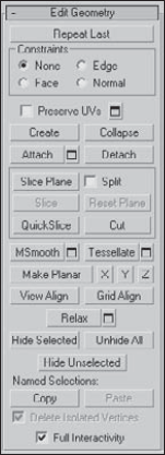
UV coordinates define how a texture map is applied to an object's surface. These UV coordinates are tied closely to the surface subobject positions, so moving a subobject after a texture is applied moves the texture also. This could cause discontinuities to the texture map. The Preserve UVs option lets you make subobject changes without altering the UV coordinates for an existing texture.
The Settings dialog box for the Preserve UVs option lets you select a Vertex Color and Texture Channel to preserve. Figure 13.7 shows two block objects with a brick texture map applied. The inner vertices on the left block were scaled outward without the Preserve UVs option selected; the right block had this option enabled.
The Create button lets you create new subobjects, specifically polygons, by connecting isolated vertices and border vertices. When the cursor is over a valid vertex, it changes to a crosshair, and you can click to create a polygon edge from the last clicked point. If no vertices are available, you can Shift-click to create one. This creates a vertex where you click. Be aware that creating a vertex doesn't add it to any of the edges, but the Create button in Edge subobject mode can connect edges to these isolated vertices.
Tip
As you create new polygons, the normal is determined by the direction in which you create the polygon using the right-hand rule. If you bend the fingers of your right hand in the direction (clockwise or counterclockwise) that the vertices are clicked, then your thumb will point in the direction of the normal. If the normal is pointing away from you, then the backside of the polygon will be visible and the lighting could be off.
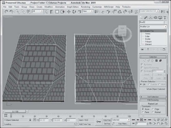
Figure 13.7. The Preserve UVs option lets you make subobject changes after texture maps have been applied.
You can use the Create button to create new polygons based on new or existing vertices. To create a new face, click the Create button, which highlights all vertices in the selected mesh. Next, click a vertex to start the polygon; after you click two more vertices, a new face is created. You can also create a new vertex not based on any existing vertices by holding down the Shift key while clicking.
Polygons aren't limited to three vertices. You can click as many times as you want to add additional vertices to the polygon. Click the first vertex, or double-click to complete the polygon.
The Collapse button is used to collapse all the selected subobjects to a single subobject located at the averaged center of the selection. This button is similar to the Weld button, except that the selected vertices don't need to be within a Threshold value to be combined. This button works in all subobject modes.
The Attach button is available with all subobject modes, even when you are not in subobject mode. Use the Attach button to add objects to the current Editable Poly object. You can add primitives, splines, patch objects, and other mesh objects. Any object attached to a mesh object is automatically converted into an editable poly and inherits the object color of the object to which it is attached. Any objects added to a poly object can be selected individually using the Element subobject mode.
Warning
If you attach an object that is smoothed using NURMS, the NURMS are lost when the object is attached.
To use this feature, select the main object and click the Attach button. Move the mouse over the object to be attached; the cursor changes over acceptable objects. Click the object to select it. Click the Attach button again or right-click in the viewport to exit Attach mode.
Note
If the object that you click to attach already has a material applied that is different from the current Editable Poly object, then a dialog box appears giving you options to Match Material IDs to Material, Match Material to Material IDs, or Do Not Modify Material IDs or Material. Materials and Material IDs are discussed in more detail in Chapter 14, "Exploring the Material Editor."
Clicking the Attach List button opens the Attach List dialog box (which looks just like the Select Objects (H) dialog box) where you can select from a list of all the objects to attach. The list contains only objects that you can attach.
Note
When you enter a subobject mode, the Attach List button changes to a Detach button for poly objects.
Attaching objects is different from grouping objects because all attached objects act as a single object with the same object color, name, and transforms. You can access individual attached objects using the Element subobject mode.
Use the Detach button to separate the selected subobjects from the rest of the object. To use this button, select the subobject and click the Detach button. The Detach dialog box opens, enabling you to name the new detached subobject. You also have the options to Detach to Element or to Detach as Clone. All subobject modes except Edge have a Detach option. This button appears in place of the Attach List button in all subobject modes.
The Slice Plane button lets you split the poly object along a plane. When you click the Slice Plane button, a yellow slice plane gizmo appears on the selected object. You can move, rotate, and scale this gizmo using the transform buttons. After you properly position the plane and set all options, click the Slice button to finish slicing the mesh. All intersected faces split in two, and new vertices and edges are added to the mesh where the Slice Plane intersects the original mesh.
The Slice Plane mode stays active until you deselect the Slice Plane button or until you right-click in the viewport; this feature enables you to make several slices in one session. The Slice Plane button is enabled for all subobject modes. For the Editable Poly object, a Reset Plane button is located next to the Slice Plane button. Use this button to reset the slice plane to its original location. You use the Split option to double the number of vertices and edges along the Slice Plane, so each side can be separated from the other. When used in Element mode, the Split option breaks the sliced object into two separate elements.
The QuickSlice button lets you click anywhere on an Editable Poly object where you want a slicing line to be located. You can then move the mouse, and the QuickSlice line rotates about the point you clicked on. When you click the mouse again, a new vertex is added at every place where the QuickSlice line intersects an object edge. This is a very convenient tool for slicing objects because the slice line follows the surface of the object, so you can see exactly where the slice will take place.
For the QuickSlice and Cut tools, you can enable the Full Interactivity option (located near the bottom of the Edit Geometry rollout). With this option enabled, the slice lines are shown as you move the mouse about the surface. With Full Interactivity disabled, the resulting lines are shown only when the mouse is clicked.
For Editable Poly objects, the Cut button is interactive. If you click a polygon corner, the cut edge snaps to the corner, and a new edge extends from the corner to a nearby corner. As you move the mouse around, the edge moves until you click where the edge should end. If you click in the middle of an edge or face, then new edges appear to the nearest corner.
When dealing with a model that includes interior parts, you may want to slice the object and separate a portion to reveal the interior. Although this can be accomplished using a camera clipping plane, which is explained in Chapter 18, "Configuring and Aiming Cameras," a more permanent solution uses the QuickSlice and Detach operations.
To combine, slice, and detach a car model, follow these steps:
Open the Sliced car.max file from the Chap 13 directory on the DVD.
Before you can slice the car, you'll need to combine the entire car into a single Editable Poly object. Select one of the body parts, right-click on it, and select the Convert To
Open the Modify panel, and click on the dialog box icon next to the Attach button in the Edit Geometry rollout.
In the Attach List dialog box that opens, click the All button and select the Attach button. In the Attach Options dialog box that appears, select the Match Material IDs to Material option and click OK.
All objects are now combined into a single Editable Poly object.
Click the QuickSlice button, and click in the Top viewport at the point where you want to slice the car. Then drag to align the slicing plane, and click again to make the slice. Click on the QuickSlice button again to exit QuickSlice mode.
Select the Polygon subobject mode, and drag over all the polygons below the slice line in the Top viewport. Then click the Detach button in the Edit Geometry rollout. In the Detach dialog box, enter the name Car Front and click OK.
Disable Polygon subobject mode, and use the Select and Move tool to separate the car front from the rest of the car.
Figure 13.8 shows the separated car front.
Both the MSmooth and Tessellate buttons include new settings dialog boxes, as shown in Figure 13.9. The MSmooth setting for Smoothness rounds all the sharp edges of an object. Tessellation can be done using Edges or Faces, and the Tension setting controls how tight the adjacent faces are.
The MSmooth button can be used to smooth the selected subobjects in the same way as the MeshSmooth modifier. This button can be used several times. The Smoothness value determines which vertices are used to smooth the object. The higher the value, the more vertices are included and the smoother the result. You can also select that the smoothing is separated by Smoothing Groups or by Materials.
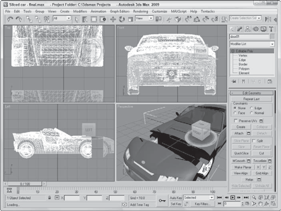
Figure 13.8. Using the Attach, QuickSlice, and Detach features, you can slice and separate mode parts.
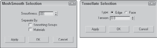
Figure 13.9. The Settings dialog boxes for the MSmooth and Tessellate buttons let you interactively set the Smoothness and Tension values.
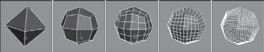
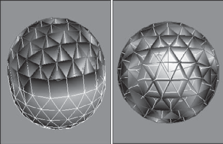
Figure 13.10 shows a simple diamond-shaped hedra that has been MeshSmoothed using the MSmooth button and then tessellated three consecutive times.
Tessellation is used to increase the density of the faces or edges. When modeling, you may want more details in a select area. This is where the tessellation command comes in. Tessellation can be applied to individual selected subobjects or to the entire object.
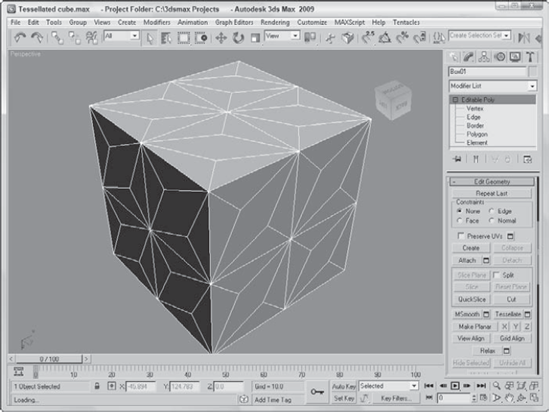
You can use the Tessellate button to increase the resolution of a mesh by splitting a face or polygon into several faces or polygons. You have two options to do this: Edge and Face.
The Edge method splits each edge at its midpoint. For example, a triangular face would be split into three smaller triangles. The Tension spinner to the right of the Tessellate button specifies a value that is used to make the tessellated face concave or convex.
The Face option creates a vertex in the center of the face and also creates three new edges, which extend from the center vertex to each original vertex. For a square polygon, this option would create six new triangular faces. (Remember, a square polygon is actually composed of two triangular faces.)
Figure 13.11 shows the faces of a cube that has been tessellated once using the Edge option and then again using the Face-Center option.
A single vertex or two vertices don't define a plane, but three or more vertices do. If three or more vertices are selected, you can use the Make Planar button to make these vertices coplanar (which means that all vertices are on the same plane). Doing so positions the selected vertices so that they lie in the same plane. This is helpful if you want to build a new polygon face. Polygonal faces need to be coplanar. This button works in all subobject modes. The X, Y, and Z buttons let you collapse the current object or subobject selection to a single plane lying on the specified axis.
The View and Grid Align buttons move and orient all selected vertices to the current active viewport or to the current construction grid. These buttons can also be used in all subobject modes. This causes all the selected face normals to point directly at the grid or view.
The Relax button works just like the Relax modifier by moving vertices so they are as far as possible from their adjacent vertices according to the Amount value listed in the Settings dialog box. The Settings dialog box also includes an Iterations value, which determines the number of times the operation is performed. You can also select to hold all Boundary and Outer points from being moved.
The Hide button hides the selected subobjects. You can make hidden objects visible again with the Unhide All button.
After selecting several subobjects, you can create a named selection set by typing a name in the Name Selection Sets drop-down list in the main toolbar. You can then copy and paste these selection sets onto other shapes.
At the bottom of the Selection rollout is the Selection Information, which is a text line that automatically displays the number and subobject type of selected items.
When working with the Editable Poly objects, after you select a Vertex subobject mode (keyboard shortcut, 1) and select vertices, you can transform them using the transform buttons on the main toolbar. All vertex-specific commands are found within the Edit Vertices rollout.
The Remove button lets you delete the selected vertices. The Remove button automatically adjusts the surrounding subobjects to maintain the mesh integrity.
Note
You can also delete Editable Poly subobjects using the Delete key.
Figure 13.12 shows a sphere object with several vertex subobjects selected. The middle image is an Editable Mesh that used the Delete feature, and the right image is an Editable Poly that used the Remove feature.
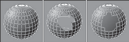
Figure 13.12. Deleting vertices also deletes the adjoining faces and edges, but Remove maintains the mesh.
The Remove button also is available in Edge subobject mode. If you hold down the Ctrl key when clicking the Remove button when an edge is selected, vertices at either end of the deleted edge are also removed.
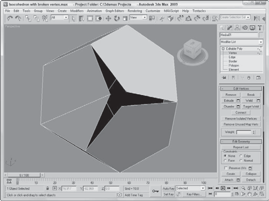
You use the Break button to create a separate vertex for adjoining faces that are connected by a single vertex.
In a normal mesh, faces are all connected by vertices: Moving one vertex changes the position of all adjoining faces. The Break button enables you to move the vertex associated with each face independent of the others. The button is available only in Vertex subobject mode.
Figure 13.13 shows a Hedra object. The Break button was used to separate the center vertex into separate vertices for each face. The face vertices can be manipulated independently, as the figure shows.
The Extrude button copies and moves the selected subobject perpendicular a given distance and connects the new copy with the original one. For example, four edges forming a square extruded would form a box with no lid. To use this feature, select an edge or edges, click the Extrude button, and then drag in a viewport. The edges interactively show the extrude depth. Release the button when you've reached the desired distance.
Alternatively, you can set an extrude depth in the Extrusion spinner. The Group option extrudes all selected edges in the direction of the average of all the normals for the group (the normal runs perpendicular to the face) and the Normal Local option moves each individual edge along its local normal. For polygons, you can extrude By Polygons, which extrudes each individual polygon along its normal as a separate extrusion. To exit Extrude mode, click the Extrude button again or right-click in the viewport.
The Extrude button is enabled for Face, Polygon, and Element subobject modes for the Editable Poly object. Figure 13.14 shows a GeoSphere object with all edges selected and extruded. The Group Normal option averages all the normals and extrudes the edges in the averaged direction. The Local Normal option extrudes each edge along its own normal.
The Extrude settings dialog box includes options for setting the Extrusion Height and the Extrusion Base Width.
Vertices and edges that are close or on top of one another can be combined together into one using the Weld command. The Weld and Chamfer buttons include settings dialog boxes that let you interactively see the results of different settings. The Weld settings dialog box includes a weld Threshold value and displays the number of vertices before and after the welding process, which is very useful to check whether a weld was successful.
Tip
If you run into trouble with the Weld button and its Threshold value, try using the Collapse button.
The Target Weld button lets you click on a single vertex and move the cursor over an adjacent vertex. A rubber band line stretches from the first selected vertex to the target weld vertex and the cursor changes to indicate that the vertex under the cursor may be selected. Clicking on the target vertex welds the two vertices together.
Note
When two vertices are welded, the new vertex is positioned at a location that is halfway between both vertices, but when Target Weld is used, the first vertex is moved to the location of the second.
The Chamfer button—which is enabled in Vertex, Edge, and Border subobject modes—lets you cut the edge off a corner and replace it with a face. Using the settings dialog box, you can interactively specify a Chamfer Amount and the number of segments. The settings dialog box also includes an Open option, which cuts a hole in the polygon face instead of replacing it with a new polygon. Figure 13.15 shows two plane objects that have been chamfered with the Open option enabled. The left plane had all its interior vertices selected, and the right plane had a selection of interior edges selected.
The Connect button can be used to add new edges to subobjects. In Vertex subobject mode, the button connects vertices on the opposite side of a face. In Edge and Border subobject mode, the button makes a settings dialog box available, which includes the Connect Edge Segments setting. This value is the number of edge segments to add between the selected edges or borders. It also includes Pinch and Slide values. The Pinch value moves the segments closer or farther away from each other; the Slide value moves the segments along the original edge.

The Remove Isolated Vertices button deletes all isolated vertices. Vertices become isolated by some operations and add unneeded data to your file. You can search and delete them quickly with this button. Good examples of isolated vertices are those created using the Create button but never attached to an edge.
The Remove Unused Map Vertices button removes any leftover mapping vertices from the object.
The Weight settings control the amount of pull that a vertex has when NURMS subdivision or a MeshSmooth modifier is used. The higher the Weight value, the more resistant a vertex is to smoothing. For edge and border subobjects, the Weight value is followed by a Crease value that determines how visible the edge is when the mesh is smoothed. A value of 1.0 ensures that the crease is visible.
Edges are the lines that run between two vertices. Edges can be closed, which means that each side of the edge is connected to a face, or open, which means that only one face connects to the edge. When a hole exists in a mesh, all edges that are adjacent to the hole are open edges. Mesh edges, such as those in the interior of a shape that has been converted to a mesh, can also be invisible. These invisible edges appear as dotted lines that run across the face of the polygon.
You can select multiple edges by holding down either the Ctrl key while clicking the edges or the Alt key to remove selected edges from the selection set. You can also copy edges using the Shift key while transforming the edge. The cloned edge maintains connections to its vertices by creating new edges.
Many of the Edge subobject options work in the same way as the Vertex subobject options.
The Split button adds a new vertex at the middle of the edge and splits the edge into two equal sections. This button is handy when you need to increase the resolution of a section quickly.
The Insert Vertex button lets you add a new vertex anywhere along an edge. The cursor changes to crosshairs when it is over an edge. Click to create a vertex. When in Edge, Border, Polygon, or Element subobject mode, this button also makes vertices visible.
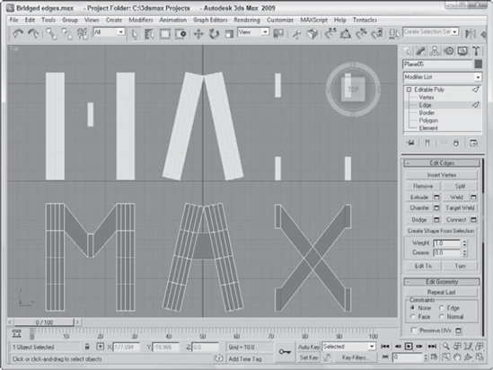
The Bridge button for edges allows you to create a new set of polygons that connect the selected edges. If two edges are selected when the Bridge button is pressed, then they are automatically connected with a new polygon. If no edges are selected, then you can click the edges to bridge after clicking the Bridge button. The selected edges on either side of the bridge can be different in number.
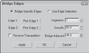
You also can access the settings dialog box for the Bridge feature. This dialog box offers the options to Bridge Specific Edges or to Use Edge Selection. The Bridge Specific Edges option has two buttons for each edge. If you click one of these buttons, you can select an edge in the viewport. The Use Edge Selection option lets you drag a marquee in the viewport to select the edges. The Bridge Edges dialog box also includes options for setting the number of Segments, the Smooth value, and a Bridge Adjacent value, which increases the triangulation for angles above the given threshold.
Figure 13.16 shows a simple example of some edges that have been bridged. The letters before bridging are on the top and after bridging on the bottom.
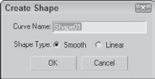
The Create Shape from Selection button creates a new spline shape from selected edges. The Create Shape dialog box appears, shown in Figure 13.17, enabling you to give the new shape a name. You can also select options for Smooth or Linear shape types.
For the Editable Poly object, the Edge, Border, Polygon, and Element subobjects include the Edit Triangulation button. The Edit Triangulation button lets you change the internal edges of the polygon by dragging from one vertex to another. When this button is clicked, all hidden edges appear. To edit the hidden edges, just click a vertex and then click again where you want the hidden edge to go. If you're dealing with multiple four-sided polygons, then the Turn button is quicker.
The Turn button rotates the hidden edges that break up the polygon into triangles (all polygonal faces include these hidden edges). For example, if a quadrilateral (four-sided) face has a hidden edge that runs between vertices 1 and 3, then the Turn button changes this hidden edge to run between vertices 2 and 4. This affects how the surface is smoothed when the polygon is not coplanar.
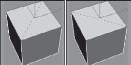
This button is available for all subobject modes except Vertex. When enabled, all subobjects that you click on are turned until the button is disabled again. Figure 13.18 shows the top face of a Box object with a hidden edge across it diagonally. The Turn button was used to turn this hidden edge.
Tip
Surfaces can deform only along places where there are edges, so as you create your models be aware of where you place edges and how the edges flow into one another. When building characters, it is important to have the edges follow the muscle flow to deform properly.
Editable Poly objects do not need the Face subobject that is found in the Editable Mesh objects because they support polygon faces. Instead, they have a Border subobject. Border subobjects are polygons with no faces that are actually holes within the geometry.
The Cap button causes the existing border selection to be filled in with a single coplanar polygon. After using this feature, the Border subobject is no longer identified as a Border subobject.
The Bridge feature joins two selected Border subobjects with a tube of polygons that connect the two borders. The two selected borders must be part of the same object and need not have an equal number of segments.
The Bridge dialog box, shown in Figure 13.19, lets you specify twist values for each edge, the number of segments, and the Taper, Bias, and Smooth values.
The Bridge tool is great for working with two border selections, allowing you to create a smooth set of polygons that flow between them. For this example, you'll create a forearm by bridging a hi-res hand model with a simple cylinder. The polygons of the hand and the cylinder that are to be joined have already been removed.
To create a forearm object by bridging a cylinder with a hand model, follow these steps:
Open the Forearm bridge.max file from the Chap 13 directory on the DVD.
With the body parts selected, open the Modify panel, and select the Border subobject mode. Then press and hold the Ctrl key, and click on the borders for the hand and cylinder objects.
With both facing Border subobjects selected, click the dialog box icon next to the Bridge button in the Edit Geometry rollout.
In the Bridge dialog box, select the Use Border Selection and set the Segments value to 6. Then click OK.
Figure 13.20 shows the resulting forearm object.
Like the other subobject modes, Editable Polys can be edited at the polygon and element subobject level. The buttons for these modes are found in the Edit Polygons and Edit Elements rollouts.
The Outline button offsets the selected polygon a specified amount. This increases the size of the selected polygon or element. The Inset button creates another polygon set within the selected polygon and connects their edges. For both these buttons, a Settings dialog box is available that includes the Outline or Inset Amount values.
The Bevel button extrudes the Polygon subobject selection and then lets you bevel the edges. To use this feature, select a polygon, click the Bevel button, drag up or down in a viewport to the Extrusion depth, and release the button. Drag again to specify the Bevel amount. The Bevel amount determines the relative size of the extruded face.
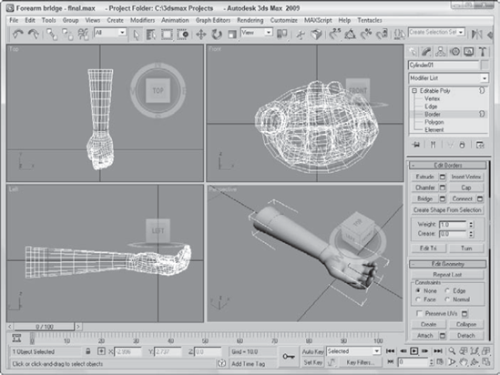
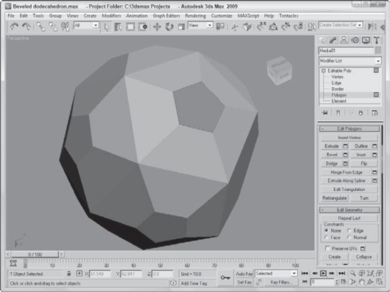
Figure 13.21 displays a poly dodecahedron. Each face has been locally extruded with a value of 20 and then locally beveled with a value of −10.
The Flip button flips the normal vectors for the selected subobjects. The Flip button is available only in Polygon and Element subobject modes.
The Retriangulate button automatically computes all the internal edges for you for the selected subobjects.
The Hinge From Edge button rotates a selected polygon as if one of its edges were a hinge. The angle of the hinge depends on the distance that you drag with the mouse, or you can use the available settings dialog box. In the settings dialog box, shown in Figure 13.22, you can specify an Angle value and the number of segments to use for the hinged section.
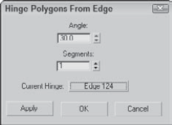
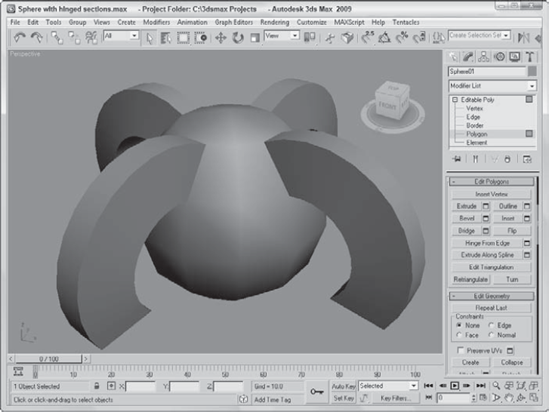
By default, one of the polygon's edges will be used as the hinge about which the section rotates, but in the settings dialog box, you can click the Pick Hinge button and select an edge (which doesn't need to be attached to the polygon). Figure 13.23 shows a sphere primitive with four polygon faces that have been hinged around an edge at the sphere's center.
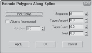
The Extrude Along Spline button can be used to extrude a selected polygon along the spline path. The settings dialog box, shown in Figure 13.24, includes a Pick Spline button that you can use to select the spline to use. You can also specify the number of segments, the Taper Amount and Curve, and a Twist value. You also have an option to Align the extrusion to the face normal or to rotate about the normal.
The one thing about an octopus that makes it unique is the fact that it has eight tentacles. Creating these tentacles can be easily accomplished with the Extrude Along Spline feature.
To create an octopus using the Extrude Along Spline feature, follow these steps:
Open the Octopus.max file from the Chap 13 directory on the DVD.
This file includes the base of an octopus created from a squashed sphere primitive that has been converted to an Editable Poly. Eight splines surround the object.
Select the octopus object to automatically open the Modify panel. In the Selection rollout, click the Polygon subobject button (keyboard shortcut, 4) and enable the Ignore Backfacing option in the Selection rollout.
Right-click the Perspective viewport title, and select the Edged Faces option from the pop-up menu (or press the F4 key).
This makes the polygons easier to see.
Click a single face object at the base of the sphere object, and click the Extrude Along Spline settings dialog box button to open the Extrude Polygons Along Spline dialog box.
Click the Pick Spline button, and select the spline to the side of the face. Set the Segments to 6 and the Taper Amount to −1.0, and click OK. Make sure that the Align to Face Normal option isn't selected.
Repeat Steps 4 and 5 for each spline surrounding the octopus.
In the Subdivisions Surface rollout, enable the Use NURMS Subdivision option and set the Display Iterations value to 2 to smooth the entire octopus.
Figure 13.25 shows the resulting octopus.
Below the Edit Geometry rollout are several rollouts of options that enable you to set additional properties such as vertex colors, material IDs, Smoothing Groups, and NURMS Subdivision.
The Vertex Properties rollout in Vertex subobject mode lets you define the Color, Illumination, and Alpha value of object vertices. The color swatches enable you to select Color and Illumination colors for the selected vertices. The Alpha value sets the amount of transparency for the vertices. After you assign colors, you can then recall vertices with the same color by selecting a color (or illumination color) in the Select Vertices By section and clicking the Select button. The RGB (red, green, and blue) values match all colors within the Range defined by these values.
Note
You can find more information on vertex colors in Chapter 31, "Creating Baked Textures and Normal Maps."
For Polygon and Element subobjects, the Polygon Properties rollout, shown in Figure 13.26, includes Material IDs and Smoothing Groups options. The Material IDs option settings are used by the Multi/Sub-Object material type to apply different materials to faces or polygons within an object. By selecting a polygon subobject, you can use these option settings to apply a unique material to the selected polygon. The Select ID button selects all subobjects that have the designated Material ID, or you can select subobjects using a material name in the drop-down list under the Select ID button.
Note
You can find more information on the Multi/Sub-Object material type in Chapter 15, "Creating and Applying Standard Materials."

Figure 13.25. The tentacles of this octopus were created easily with the Extrude Along Spline feature.
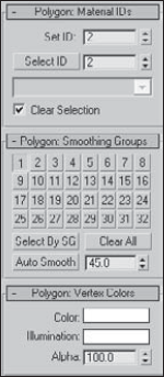
Figure 13.26. The Polygon Properties rollout includes settings for Material IDs, Smoothing Groups, and Vertex Colors.
You use the Smoothing Groups option to assign a subobject to a unique smoothing group. To do this, select a subobject and click a Smoothing Groups number. The Select By SG button, like the Select By ID button, opens a dialog box where you can enter a Smoothing Groups number, and all subobjects with that number are selected. The Clear All button clears all Smoothing Groups number assignments, and the Auto Smooth button automatically assigns Smoothing Groups numbers based on the angle between faces as set by the value to the right of the Auto Smooth button.
The Polygon Properties rollout also includes options for setting vertex Color, Illumination, and Alpha values.
Editable Poly objects include an extra rollout called Subdivision Surface that automatically smoothes the object when enabled. The Subdivision Surface rollout, shown in Figure 13.27, applies a smoothing algorithm known as NURMS, which stands for Non-Uniform Rational Mesh Smooth. It produces similar results to the MSmooth button but offers control over how aggressively the smoothing is applied; the settings can be different for the viewports and the renderer.
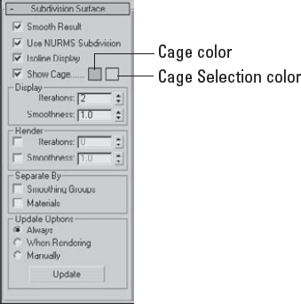
To enable NURMS subdivision, you need to enable the Use NURMS Subdivision option. The Smooth Result option places all polygons into the same smoothing group and applies the MeshSmooth to the entire object. Applying NURMS with a high Iterations value results in a very dense mesh, but the Isoline Display option displays a simplified number of edges, making the object easier to work with. The process of smoothing adds many edges to the object, and the Isoline Display option displays only the isolines. The Show Cage option makes the surrounding cage visible or invisible. The two color swatches to the right of the Show Cage option let you set the color of the cage and the selection.
The Iterations value determines how aggressive the smoothing is. The higher the Iterations value, the more time it takes to compute and the more complex the resulting object. The Smoothness value determines how sharp a corner must be before adding extra faces to smooth it. A value of 0 does not smooth any corners, and a maximum value of 1.0 smoothes all polygons.
Warning
Each smoothing iteration quadruples the number of faces. If you raise the number of Iterations too high, the system can become unstable quickly.
The two check boxes in the Render section can be used to set the values differently for the Display and Render sections. If disabled, then both the viewports and the renderer use the same settings. The smoothing algorithm can be set to ignore smoothing across Smoothing Groups and Materials.
If the Show Cage option is enabled (at the bottom of the Edit Geometry rollout), an orange cage surrounds the NURMS object and shows the position of the polygon faces that exist if NURMS is disabled. This cage makes selecting the polygon faces easier.
If you've ever had a root canal, then you know how much pain dental work can cause. Luckily, modeling a tooth isn't painful at all, as you'll see in this example.
To model a tooth using NURMS, follow these steps:
Select Create
Click the Polygon icon in the Selection rollout to enable Polygon subobject mode. Then select the Top viewport, and press B to change it to the Bottom viewport. Then click the box's bottom polygon in the Bottom viewport.
Click the Select and Scale button (R), and scale the bottom polygon 10%.
Drag over the entire object to select all polygons, and click the Tessellate button in the Edit Geometry rollout once to divide the polygon into more polygons. Then select Edit
Select the Vertex subobject mode in the Selection rollout, press and hold the Ctrl key, and select the vertices at the center of each quadrant. Then move these vertices downward in the Left viewport a distance about equal to the height of the Box.
Select the Bottom viewport again, and press T to change it back to the Top viewport. Select the single vertex in the center of the polygon with the Ignore Backfacing option enabled in the Selection rollout, and drag it slightly downward in the Left viewport.
Disable the Ignore Backfacing option in the Selection rollout, and select the entire second row of vertices in the Left viewport. With the Select and Scale tool, scale these vertices toward the center in the polygon in the Top viewport.
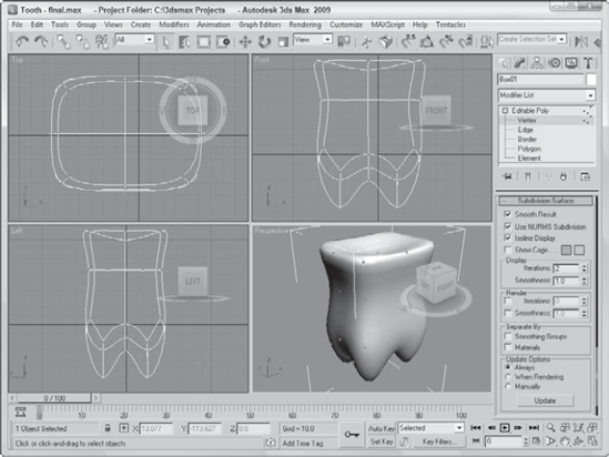
In the Subdivision Surface rollout, enable the Use NURMS Subdivision option and set the Iterations value to 2.
Figure 13.28 shows the completed tooth.
Meshes are probably the most common 3D modeling types. You can create them by converting objects to Editable Meshes or Editable Poly objects or by collapsing the Stack. Editable Poly objects in Max have a host of features for editing meshes, as you learned in this chapter. More specifically, this chapter covered the following topics:
Creating Editable Poly objects by converting other objects or applying the Edit Poly modifier
The features for editing Editable Poly objects
How to select and use the various mesh subobject modes
Editing mesh objects using the various features found in the Edit Geometry rollout
Changing surface properties using features like NURMS
This chapter concludes Part III, "Modeling Basics." You're now ready to learn about dressing up objects with materials, cameras, and lights. The next chapter covers the basics of applying materials.