
Now that you've learned to create materials using the Standard material type, you get a chance to see the variety of material types that you can create in Max. You can select all the various Max materials from the Material/Map Browser. Open this browser automatically by clicking the Material Type button beneath the sample slots.
Although many of these materials are called compound materials, they are really just collections of materials that work together as one. Just like a mesh object can include multiple elements, materials also can be made up of several materials. Using Material IDs, you can apply multiple materials to the subobject selections of a single mesh object. The chapter concludes with a quick look at the various modifiers that are applied to materials.
Compound materials combine several different materials into one. You select a compound object type by clicking the Type button in the Material Editor and then selecting the material type from the Material/Map Browser. The Type button is the button to the right of the material name. It lists the current material on the button, such as Standard, which is the default material. Most of the entries in the Material/Map Browser are compound objects.
Whenever compound materials are selected, the Replace Material dialog box appears, asking whether you want to discard the current material or make the old material a submaterial. This feature enables you to change a normal material into a compound material while retaining the current material.
Compound materials usually include several different levels. For example, a Top/Bottom material includes a separate material for the top and the bottom. Each of these submaterials can then include another Top/Bottom material, and so on. The Material/Map Navigator dialog box (accessed by clicking the Material/Map Navigator button) displays the material as a hierarchical list. This list lets you easily choose the level you want to work with.
Note
Chapter 14, "Exploring the Material Editor," covers the Material/Map Navigator in more detail.
Each compound material includes a customized rollout for specifying the submaterials associated with the compound material.
Note
Some of the material types work closely with specific objects and other Max features. These materials are covered in their respective chapters. The Advanced Lighting Override and Lightscape materials are presented in Chapter 44, "Working with Advanced Lighting, Light Tracing, and Radiosity," the raytracing and various mental ray material settings are covered in detail in Chapter 46, "Raytracing and mental ray," and the XRef material is covered in Chapter 23, "Building Complex Scenes with XRefs and Using Vault."
The Blend material blends two separate materials on a surface. The Blend Basic Parameters rollout, shown in Figure 16.1, includes buttons for loading the two submaterials. The check boxes to the right of these buttons enable or disable each submaterial. The Interactive option enables you to select one of the submaterials to be viewed in the viewports.
The Mask button (which appears below the two submaterial buttons) lets you load a map to specify how the submaterials are mixed. Gray areas on the map are well blended, white areas show Material 1, and black areas show Material 2. As an alternative to a mask, the Mix Amount determines how much of each submaterial to display. A value of 0 displays only Material 1, and a value of 100 displays only Material 2. This value can be animated, allowing an object to gradually change between materials.
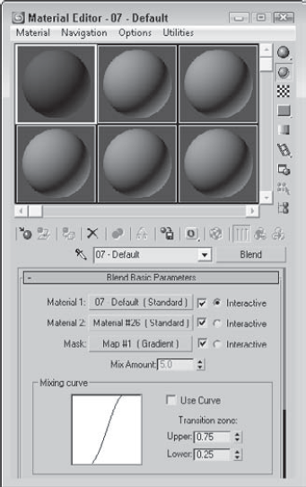
The Mixing curve defines the transition between edges of the two materials. The Upper and Lower spinners help you control the curve.
The Composite material mixes up to ten different materials by adding, subtracting, or mixing the opacity. The Composite Basic Parameters rollout, shown in Figure 16.2, includes buttons for the base material and nine additional materials that can be composited on top of the base material. The materials are applied from top to bottom.
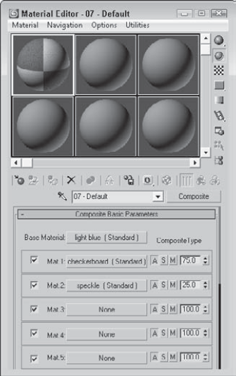
Figure 16.2. Composite materials are applied from top to bottom, with the last layer placed on top of the rest.
You enable or disable each material using the check box to its left. The buttons labeled with the letters A, S, and M specify the opacity type: Additive, Subtractive, or Mix. The Additive option brightens the material by adding the background colors to the current material. The Subtractive option has the opposite effect and subtracts the background colors from the current material. The Mix option blends the materials based on their Amount values.
To the right of the A, S, and M buttons is the Mix amount. This value can range from 0 to 200. At 0, none of the materials below it will be visible. At 100, full compositing occurs. Values greater than 100 cause transparent regions to become more opaque.
Note
You can learn more about compositing and the Video Post interface in Chapter 48, "Compositing with Render Elements and the Video Post Interface."
The Double Sided material specifies different materials for the front and back of object faces. You also have an option to make the material translucent. This material is for objects that have holes in their surface. Typically, objects with surface holes do not appear correctly because only the surfaces with normals pointing outward are visible. Applying the Double Sided material shows the interior and exterior of such an object.
The Double Sided Basic Parameters rollout includes two buttons, one for the Facing material and one for the Back material. The Translucency value sets how much of one material shows through the other.
You can use the Multi/Sub-Object material to assign several different materials to a single object via the material IDs. You can use the Mesh Select modifier to select each subobject area to receive the different materials.
At the top of the Multi/Sub-Object Basic Parameters rollout, shown in Figure 16.3, is a Set Number button that lets you select the number of subobject materials to include. This number is displayed in a text field to the left of the button. Each submaterial is displayed as a separate area on the sample object in the sample slots. Using the Add and Delete buttons, you can selectively add or delete submaterials from the list.
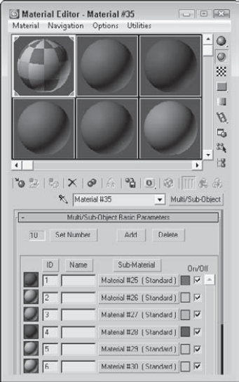
Each submaterial includes a sample preview of the submaterial and an index number listed to the left, a Name field where you can type the name of the submaterial, a button for selecting the material, a color swatch for creating solid color materials, and a check box for enabling or disabling the submaterial. You can sort the submaterials by clicking the ID, Name, or Sub-Material buttons at the top of each column.
After you apply a Multi/Sub-Object material to an object, use the Mesh Select modifier to make a subobject selection. In the Material section for this subobject selection, choose a material ID to associate with a submaterial ID or select the material by name from the drop-down list.
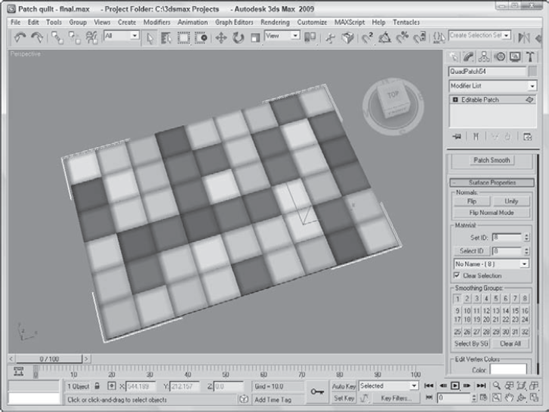
When I think of patches, I think of a 3D Max object type, but for many people, "patches" instead bring to mind small scraps of cloth used to make a quilt. Because they share the same name, this example uses Max patches to create a quilt. You can then use the Multi/Sub-Object material to color the various patches appropriately.
Note
You can learn more about modeling with patches in Chapter 27, "Modeling with Patches and NURBS."
To create a quilt using patches, follow these steps:
Open the Patch quilt.max file from the Chap 16 directory on the DVD.
This file contains a quilt made of patch objects that have been combined into one object.
Open the Material Editor by choosing Rendering

The Multi/Sub-Object material loads into the selected sample slot, and the Multi/Sub-Object Basic Parameters rollout displays in the Material Editor.
In the Multi/Sub-Object Basic Parameters rollout, click the color swatches to the right of the Material button to open the Color Selector. Select different colors for each of the first ten material ID slots.
Drag the Multi/Sub-Object material from its sample slot in the Material Editor, and drop it onto the patch object. Close the Material/Map Browser and the Material Editor.
In the Modify panel, select the Patch subobject and scroll to the bottom of the Modify panel to the Surface Properties rollout.
Assign each patch a separate material ID by clicking a patch and changing the ID number in the rollout field.
Figure 16.4 shows the finished quilt. Because it's a patch, you can drape it over objects easily.
The Morpher material type works with the Morpher modifier to change materials as an object morphs. For example, you can associate a blushing effect with light red applied to the cheeks of a facial expression to show embarrassment. You can use this material only on an object that has the Morpher modifier in its Stack. The Morpher modifier includes a button called Assign New Material in the Global Parameters rollout for loading the Material Editor with the Morpher material type.
Note
Discover more about the Morpher modifier in Chapter 32, "Using Animation Modifiers."
For the Morpher material, the Choose Morph Object button in the Morpher Basic Parameters rollout lets you pick a morpher object in the viewports and then open a dialog box used to bind the Morpher material to an object with the Morpher modifier applied. The Refresh button updates all the channels. The base material is the material used before any channel effects are used.
The Morpher material includes 100 channels that correlate to the channels included in the Morpher modifier. Each channel can be turned on and off. At the bottom of the parameters rollout are three Mixing Calculation options that can be used to determine how often the blending is calculated. The Always setting can consume lots of memory and can slow down the system. Other options are When Rendering and Never Calculate.
The Shell Material consists of an original material and a baked material. For each of these materials, you can specify which appear in the viewport and which are rendered.
Note
More on baked materials is found in Chapter 31, "Creating Baked Textures and Normal Maps."
The Shellac material is added on top of the Base material. The Shellac Basic Parameters rollout includes only two buttons for each material, along with a Color Blend value. The Blend value has no upper limit.
The Top/Bottom material assigns different materials to the top and bottom of an object. The Top and Bottom areas are determined by the direction in which the face normals point. These normals can be according to the World or Local Coordinate System. You can also blend the two materials.
The Top/Bottom Basic Parameters rollout includes two buttons for loading the Top and Bottom materials. You can use the Swap button to switch the two materials. Using World coordinates enables you to rotate the object without changing the material positions. Local coordinates tie the material to the object.
The Blend value can range from 0 to 100, with 0 being a hard edge and 100 being a smooth transition. The Position value sets the location where the two materials meet. A value of 0 represents the bottom of the object and displays only the top material. A value of 100 represents the top of the object, and only the Bottom material is displayed.
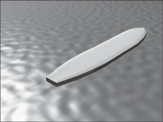
There's nothing like hitting the surf early in the morning, unless you consider hitting the virtual surf early in the morning. As an example of a compound material, you apply the Top/Bottom material to a surfboard.
To apply a Top/Bottom compound material to a surfboard, follow these steps:
Open the Surfboard.max file from the Chap 16 directory on the DVD.
This file contains a surfboard model and an infinite plane to represent the ocean.
Apply the Ocean Surface material, which is already created in the Material Editor, to the plane object by dragging the material from the Material Editor to the Plane object.
In the Material Editor, select the second sample slot and click the Type button. From the Material/Map Browser, select the Browse From New option and double-click the Top/Bottom material.
When the Replace Material dialog box appears, select the Discard Old Material option. Type the name Surfboard for the new material. Then click the Top Material button, name the material Surfboard Top, and change the Diffuse color to White. In the material drop-down list, select Surfboard and then click the Bottom Material button. Give this material the name Surfboard Bottom, and change the Diffuse color to Black.
Click the Material/Map Navigator button to view the hierarchy of the material. Then drag this material to the surfboard object.
Figure 16.5 shows the resulting image.
Most complex models are divided into multiple parts, each distinguished by the material type that is applied to it. For example, a car model would be separated into windows, tires, and the body, so that each part can have a unique material applied to it.
Sometimes you may want to apply multiple materials to a single part. Selecting subobject areas and using material IDs can help you accomplish this task.
Many of the standard primitives have material IDs automatically assigned: Spheres get a single material ID, boxes get six (one for each side), and cylinders get three (one for the cylinder and one for each end cap). In addition to the standard primitives, you can assign material IDs to Editable Mesh objects. You also can assign these material IDs to any object or subobject using the Material modifier. These material IDs correspond to the various materials specified in the Multi/Sub-Object material.
Note
Don't confuse these material IDs with the material effect IDs, which are selected using the Material Effect flyout buttons under the sample slots. Material IDs are used only with the Multi/Sub-Object material type, whereas the effect IDs are used with the Render Effects and Video Post dialog boxes for adding effects such as glows to a material.
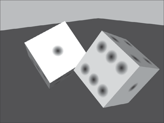
As an example of mapping multiple materials to a single object, consider a die. Splitting the cube object that makes up the die into several different parts wouldn't make sense, so you'll use the Multi/Sub-Object material instead.
To create a die model, follow these steps:
Open the Pair of dice.max file from the Chap 16 directory on the DVD.
This file contains two simple cube primitives that represent a pair of dice. I also used Adobe Photoshop and created six images with the dots of a die on them. All of these images are the same size.
Open the Material Editor, and select the first sample slot. Name the material Die Faces, and click the Type button. Select the Multi/Sub-Object material from the Material/Map Browser. In the dialog box that opens, select to discard the current map and click OK.
In the Multi/Sub-Object Basic Parameters rollout, click the Set Number button and enter a value of 6.
Name the first material face 1, and click the material button to open the parameter rollouts for the first material. Then click the map button to the right of the Diffuse color swatch to open the Material/Map Browser, and double-click the Bitmap map. In the Select Bitmap Image File dialog box, choose the dieface1.tif image from the Chap 16 directory on the DVD and click Open.
Back in the Material Editor, click the Go to Parent button twice to return to the Multi/Sub-Object Basic Parameters rollout and repeat Step 4 for each of the die faces.
When the Multi/Sub-Object material is defined, select the cube object and click the Assign Material to Selection button.
Note
Because the cube object used in this example is a box primitive, you didn't need to assign the material IDs to different subobject selections. The box primitive automatically assigned a different material ID to each face of the cube. When material IDs do need to be assigned, you can specify them in the Surface Properties rollout for editable meshes.
Figure 16.6 shows a rendered image of two dice being rolled.
Tip
If you enable the Show Map in Viewport option in the Material Editor, then the subobject materials are visible; you also can enable them using the Views
All compound materials have submaterials that are used to add layers of detail to the material, but if these submaterials aren't used, they can take up memory and disk space. You can locate and eliminate unused submaterials in the scene using the Clean MultiMaterial utility. This utility can be accessed from the Utility panel or from the Utilities menu in the Material Editor. For example, if you create a Multi/Sub-Object material with seven submaterials but later as you are modeling find that you need only five, the two unneeded submaterials can be cleaned.
Clicking the Find All button finds all submaterials that aren't used and presents them in a list where you can select the ones to clean.
Of the many available modifiers, most modifiers change the geometry of an object, but several work specifically with materials and maps, including the Material MaterialByElement, Disp Approx, and Displace Mesh (WSM) modifiers in the Surface category; and the Vertex Paint modifier in the Mesh Editing category. In this section, you get a chance to use several material-specific modifiers.
The Material modifier lets you change the material ID of an object. The only parameter for this modifier is the Material ID. When you select a subobject and apply this modifier, the material ID is applied only to the subobject selection. This modifier is used in conjunction with the Multi/Sub-Object Material type to create a single object with multiple materials.
The MaterialByElement modifier enables you to change material IDs randomly. You can apply this modifier to an object with several elements. The object needs to have the Multi/Sub-Object material applied to it.
The parameters for this modifier can be set to assign material IDs randomly with the Random Distribution option or according to a desired Frequency. The ID Count is the minimum number of material IDs to use. You can specify the percentage of each ID to use in the fields under the List Frequency option. The Seed option alters the randomness of the materials.
The MaterialByElement modifier enables you to change material IDs randomly. In this tutorial, you reproduce the effect of lights randomly turning a marquee on and off by using the Multi/Sub-Object material together with the MaterialByElement modifier.
To create a randomly lighted marquee, follow these steps:
Open the Marquee Lights.max file from the Chap 16 directory on the DVD.
This file includes some text displayed on a rectangular object surrounded by spheres that represent lights.
Open the Material Editor, and select the first sample slot. Then click the Type button, and select the Multi/Sub-Object material from the Material/Map Browser. Select to discard the current material, and click OK. Give the material the name Random Lights.
In the Multi/Sub-Object Basic Parameters rollout, click the Set Number button and change its value to 2. Then click the Material 1 button, and in the Material name field, give the material the name Light On. Set the Diffuse color to yellow and Self-Illumination to yellow. Then click the Go Forward to Sibling button to access the second material.
Name the second material Light Off, and select a gray Diffuse color. Then click the Go to Parent button to return to the Multi/Sub-Object material.
Select all the spheres, and click the Assign Material to Selection button to assign the material to the spheres.
With all the spheres selected, open the Modify panel and select the MaterialByElement modifier from the Modifier List drop-down list. In the Parameters rollout, select the Random Distribution option and set the ID Count to 2.
Figure 16.7 shows the marquee with its random lights. (I've always wanted to see my name in lights!)
You can change the geometry of an object in several ways using a bitmap. One way is to use the Displace modifier (found in the Modifiers
Another way to displace geometry with a bitmap is to use a displacement map. Displacement maps can be applied directly to Editable Poly and Mesh, NURBS, and Patch objects. If you want to apply a displacement map to another object type, such as a primitive, you first need to apply the Modifiers
Note
More details on working with maps are covered in Chapter 17, "Adding Material Details with Maps."

One drawback to using displacement maps is that you cannot see their result in the viewport, but if you apply the Modifiers
Note
The Displace modifier requires a dense mesh in order to see the results of the displacement map, but the Disp Approx modifier creates the required density at render time.
When faced with how to displace an object using a bitmap, Max once again comes through with several ways to accomplish the task. The method you choose depends on the pipeline. You can choose to keep the displacement in the Modifier Stack or on the material level. This simple tutorial compares using both these methods.
To compare the Displace modifier with a displacement map, follow these steps:
Create two square-shaped plane objects side by side in the Top viewport using the Create
Tip
When displacing geometry using a bitmap, make sure the object faces that will be displaced have sufficient resolution to represent the displacement.
Select the first plane object and apply the Displace modifier with the Modifiers
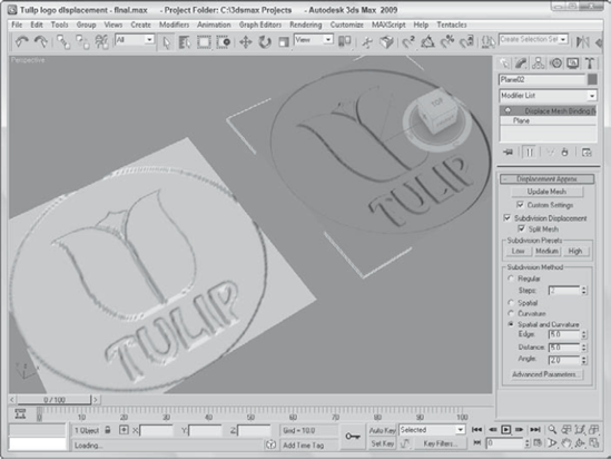
Select the second plane object and open the Material Editor by pressing the M key. In the Material Editor, open the Maps rollout, set the Displacement Map Amount value to 10, and click the Displacement map button. Then double-click on the Bitmap option in the Material/Map Browser, and load the same Tulip logo.tif file from the Chap 16 directory on the DVD. Then apply the material to the second plane object by pressing the Assign Material to Selection button, and close the Material Editor.
With the second plane still selected, choose the Modifiers
Figure 16.8 shows the resulting displacement on both plane objects.
When creating models that are for games, the size of the texture map can be prohibitive. I mean, what model that weighs in at 16KB or less wants to carry around a 2MB texture map? The solution that much of the gaming world relies on is to apply a single color to a vertex. Having each vertex remember its color (or even several colors) requires very little additional information for the mesh and can create some good shading. Colors are then interpolated across the face of the polygon between two different colors on adjacent vertices.
The results aren't as clean and detailed as a texture map, but for their size, vertex colors are worth the price.
Vertex colors can be assigned in the Surface Properties rollout for Editable Mesh and Editable Patch objects, and in the Vertex and Polygon Properties rollouts for Editable Poly objects. They also can be assigned in Face, Polygon, and Element subobject modes using a little rollout section called Edit Vertex Colors. Within this section are two color swatches for selecting Color and Illumination values. The Alpha value sets the alpha transparency value for the vertex.
Another, more interactive way to color vertices is with the Vertex Paint modifier. This modifier lets you paint on an object by specifying a color for each vertex. If adjacent vertices have different colors assigned, then a gradient is created across the face. The benefit of this coloring option is that it is very efficient and requires almost no memory.
The Vertex Paint modifier lets you specify a color and paint directly on the surface of an object by painting the vertices. The color is applied with a paintbrush-shaped cursor. The modifier can be applied multiple times to an object, giving you the ability to blend several layers of vertex paints together. You can find this modifier in the Modifiers
Note
Once the VertexPaint modifier has been applied to an object, the Paintbox automatically reappears whenever the object is reselected.
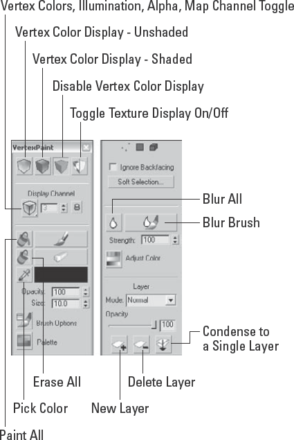
Applying this modifier opens a VertexPaint dialog box called the Paintbox, shown in Figure 16.9. At the top of the Paintbox are four icons that can be used to show the visible results of the painting in the viewports. The options include Vertex Color Display–Unshaded, Vertex Color Display–Shaded, Disable Vertex Color Display, and Toggle Texture Display On/Off.
The Vertex Color icon flyout lets you work on the Vertex Color, Illumination, Alpha, or any one of the 99 available map channels. The lock icon locks the display to the selected channel, or you could be looking at a different channel from the one you are painting.
The large Paint and Erase buttons let you add or remove vertex colors using the color specified in the color swatch. You can also select colors from objects in the viewports using the eyedropper tool and then set the Opacity.
The Size value determines the size of the brush used to paint. Max supports pressure-sensitive devices such as a graphics tablet, and you can set the brush options using the Brush Options dialog box. When paining on the surface of an object, a blue normal line appears. This line guides you as you paint so that you know you're on the correct surface.
Note
The Painter Options dialog box also is used by the Skin modifier and the Paint Deformation tool. It is described in detail in Chapter 13, "Modeling with Polygons."
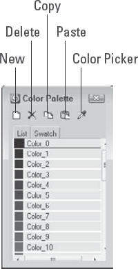
Beneath the Brush Options button is a Palette button that opens the Color Palette interface, shown in Figure 16.10. The Color Palette holds custom colors and lets you copy and paste colors between the different swatches. Collections of colors can be saved by right-clicking the Color Palette and selecting the Save As command. Color palettes are saved as Color Clipboard files with the .ccb extension.
The Paintbox also includes three subobject selection icons. These icons can be used to select certain Vertices, Faces, or Elements to be painted. This limits the painting to the selected subobjects only. You also can select to Ignore Backfacing and use Soft Selection.
The Blur brush button lets you blur colors across polygons using a brush that works just like the Paint and Erase brushes.
The Adjust Color dialog box lets you change all the painted colors applied to an object using HSV or RGB color sliders. The Preview option makes the color adjustment visible in the viewports if selected. Below the Adjust Color icon is the Blur Selected icon that blurs together all the vertex colors based on the designated Amount value.
Colors can be mixed between layers using the various blending modes. Clicking the New Layer button adds a new instance of the Vertex Paint modifier to the Modifier Stack; the Delete Layer button does the opposite. Click the Condense to a Single Layer button to merge all the consecutive Vertex Paint modifiers to a single instance using the selected blending mode.
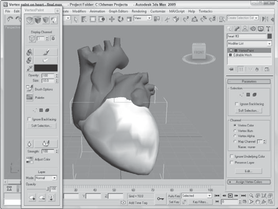
As an example of using the Vertex Paint modifier, imagine a doctor who has a 3D model of the human heart. While discussing the results of the latest test with a patient, the doctor can color parts of the heart model to illustrate the various points.
To color on a human heart using the Vertex Paint modifier, follow these steps:
Open the Vertex paint on heart.max file from the Chap 16 directory on the DVD.
This file includes a heart mesh created by Viewpoint Datalabs.
Select a portion of the heart model, and choose Modifiers
In the Paintbox that opens, choose the Vertex Color Display–Shaded button at the top of the VertexPaint dialog box, select the red color, and click the Paint button. Then drag the mouse over the surface of the Perspective view.
Figure 16.11 shows the resulting color.
The Assign Vertex Color utility works a little differently. It converts any existing material colors to vertex colors. To use this utility, select the utility from the Utilities list that opens when the More button in the Utility panel is clicked, select an object, choose a Channel, choose a Light Model (Lighting + Diffuse, Lighting Only, or Diffuse Only), and click the Assign to Selected button.
This chapter introduced several compound materials that you can create in Max. The chapter presented various material types, including compound, and multi/sub-object, materials. The chapter also showed off a number of key material modifiers including the Displace Mesh and Vertex Paint modifiers.
The following topics were covered in this chapter:
Various compound material types
Applying multiple materials to an object with material IDs
Exploring several material modifiers, including the Material and MaterialByElement
Comparing the different displacement methods
Using Vertex Colors to paint models
The one big rollout not covered deals with maps. The next chapter delves into the topic of material maps.