
CHAPTER 26
Deforming Surfaces and Using the Mesh Modifiers
Using the Paint Deformation brush
Maintaining primitive objects with the Edit Mesh and Edit Poly modifiers
Changing mesh geometry with modifiers
Editing mesh normals
Working with Subdivision Surfaces
When an Editable Poly object is selected, three specific deformation brushes may be selected in the Paint Deformation rollout. Using these brushes, you can deform the surface of an object by dragging over the surface with the selected brush.
In addition to the editing features available for Editable Mesh and Editable Poly objects and the Paint Deformation brushes, you also can modify mesh geometries using modifiers. The Modifiers menu includes a submenu of modifiers that are specific to mesh (and poly) objects. These modifiers are found in the Mesh Editing submenu and can be used to enhance the features available for these objects.
Another set of modifiers that apply specifically to mesh objects are the Subdivision Surface modifiers. These modifiers are also covered in this chapter.
The Basics of Deformation Painting
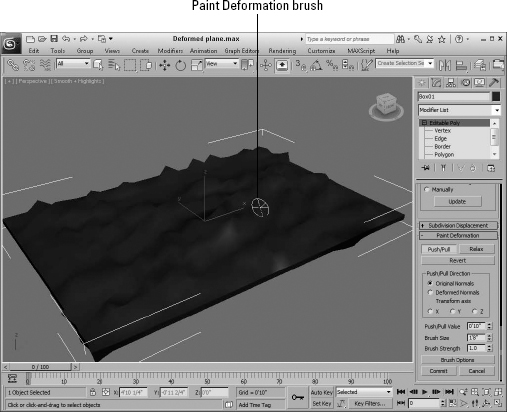
The first thing to remember about the Paint Deformation feature is that it is available only for Editable Poly objects (or objects with the Edit Poly modifier applied). When an Editable Poly object is selected, the Paint Deformation rollout appears at the very bottom of the Modify panel in the Command Panel.
Painting deformations
At the top of the Paint Deformation rollout are three buttons used to select the type of deformation brush to use. These three brushes are the Push/Pull brush, the Relax brush, and the Revert brush.
When one of these brushes is selected, the mouse cursor changes to a circular brush, shown in Figure 26.1, that follows the surface of the object as you move the mouse over the object. A single line points outward from the center of the circle in the direction of the surface normal. Dragging the mouse affects the surface in a certain manner, depending on the brush that is selected.
Dragging the Paint Deformation brush over the object surface deforms the surface by moving the vertices within the brush's area. The direction that the vertices are moved follows the surface normals by default, or you can have the deformation follow a deformed normal or along a specified transform axis. For example, if you select to deform vertices along the X-axis, then all vertices underneath the brush are moved along the X-axis as the brush is dragged over the surface.
FIGURE 26.1 The Paint Deformation brush looks like a circle that follows the surface.
Deformations created using the Paint Deformation brushes cannot be animated. For objects with the Edit Poly modifier applied, the Paint Deformation brushes are disabled when in Animate mode.
The Push/Pull value determines the distance that the vertices are moved, thereby setting the amount of the deformation. The Brush Size sets the size (or radius) of the brush and determines the area that is deformed. The Brush Strength value sets the rate at which the vertices are moved. For example, if the Push/Pull Value is set to 100 mm, then a Brush Strength value of 1.0 causes the vertices directly under the brush center to move 100 mm; a Brush Strength value of 0.4 causes the same vertices to move only 40 mm.
Tip
Holding down the Shift and Alt keys while dragging in the viewports lets you interactively change the Brush Strength value.
Accessing brush presets
If you right-click the main toolbar away from any of the buttons, you can access the Brush Presets toolbar, shown in Figure 26.2, from the pop-up menu.
FIGURE 26.2 The Brush Presets toolbar lets you quickly select from a selection of predefined brushes.
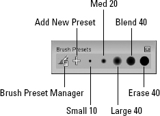
The first toolbar button opens the Brush Preset Manager, shown in Figure 26.3. From this interface, you can choose to create preset brushes for each of the different features that use brushes—Vertex Paint, Paint Deformation, Paint Soft Selection, Viewport Canvas, and Paint Skin Weights. The Add button works the same as the Add New Preset toolbar button. It opens a dialog box where you can name the new preset. The new preset is then added to the list of presets.
Note
The brushes in the Brush Presets toolbar become active only when one of the features that use brushes is selected.
FIGURE 26.3 The Brush Preset Manager lets you create new preset brushes.
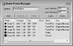
When a brush preset is selected on the Brush Presets toolbar, you can change its attributes using the Painter Options dialog box. The Paint Deformation rollout also includes a button for accessing the Painter Options dialog box. Any changes to the brush attributes are automatically updated in the Brush Preset Manager. The Load and Save buttons in the Brush Preset Manager dialog box let you save and load brush preset sets. The brush options are covered later in this chapter.
Using the Deformation Brushes
The Push/Pull brush may be used to pull vertices away from the object surface or to indent the surface by moving the surface toward the object's center. The difference is determined by the Push/Pull value. Positive values pull vertices, and negative values push vertices.
Tip
Holding down the Alt key while dragging reverses the direction of the Push/Pull brush, causing a pull brush to push and vice versa.
Controlling the deformation direction
By default, dragging over vertices with the Push/Pull brush causes the affected vertices to be moved inward or outward along their normals. If you drag over the same vertices several times, they are still deformed using the original face normals.
The Deformed Normals option causes the vertices to be moved in the direction of the normal as the normals are deformed. Using the Original Normals option causes the deformed area to rise from the surface like a hill with a gradual increasing height. The Deformed Normals option causes the deformed area to bubble out from the surface.
The Transform Axis option causes the vertices to be moved in the direction of the selected transform axis. This option is useful if you want to skew or shift the deformed area.
Limiting the deformation
If a subobject selection exists, then the vertices that are moved are limited to the subobject area that is selected. You can use this to your advantage if you want to make sure that only a certain area is deformed.
Committing any changes
After you make some deformation changes, the Commit and Cancel buttons become active. Pressing the Commit button makes the changes permanent, which means that you can no longer return the vertices to their original location with the Revert brush. The Cancel button rejects all the recent deformation changes.
Using the Relax and Revert brushes
The Relax brush provides a much more subtle change. It moves vertices that are too close together farther apart, causing a general smoothing of any sharp points. It works the same way as the Relax feature for the Editable Poly object and the Relax modifier.
The Revert brush is used to return to their original position any vertices that have moved. For example, if you pushed and pulled several vertices, the Revert brush can undo all of these changes for the area under the brush cursor.
Tip
Holding down the Ctrl key while dragging with the Push/Pull brush lets you temporarily access the Revert brush.
Tutorial: Adding veins to a forearm
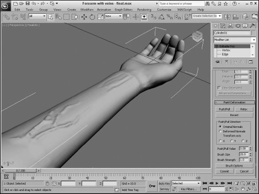
The Paint Deformation feature is very useful in adding surface details to organic objects such as the veins of a forearm.
To add veins to a forearm object, follow these steps:
- Open the Forearm with veins.max file from the Chap 26 directory on the CD.
The polygons that make up the forearm object have been selected and tessellated to increase its resolution.
- With the forearm object selected, open the Modify panel and in the Paint Deformation rollout, click the Relax button. Set the Brush Size to 1.0, and drag over the entire forearm.
This smoothes out some of the vertical lines that run along the forearm.
- Click the Push/Pull button, and set the Push/Pull Value to 0.15, the Brush Size to 0.08, and the Brush Strength to 0.5. Then draw in some veins extending from the elbow toward the hand.
- Lower the Brush Strength value to 0.25, and extend the vein farther down the arm. Then drop the Brush Strength to 0.1, and finish the veins.
- With the Push/Pull brush still selected, hold down the Alt key and drag near the wrist to indent the surface around the area where the hand tendons are located.
Figure 26.4 shows the resulting forearm.
FIGURE 26.4 The Paint Deformation brushes are helpful in painting on raised and indented surface features.
Setting Painter Options
At the bottom of the Paint Deformation rollout is a button labeled Brush Options. Clicking this button opens the Painter Options dialog box, shown in Figure 26.5. Using this dialog box, you can set several customized brush options, including the sensitivity of the brush.
Cross-Reference
The Painter Options dialog box is also used by the brushes to paint vertex colors for the Vertex Paint modifier and to paint skin weights as part of the Skin modifier. The Vertex Paint modifier is covered in Chapter 34, “Creating Baked Textures and Normal Maps,” and the Skin modifier is covered in Chapter 40, “Skinning Characters.”
FIGURE 26.5 The Painter Options dialog box includes a graph for defining the minimum and maximum brush strengths and sizes.
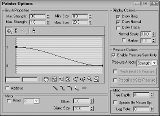
The Min/Max Strength and Min/Max Size values determine the minimum and maximum weight values and paint gizmo sizes. You can define the brush falloff using the curve. This keeps the weights from making an abrupt change (muscles tend to look funny when this happens). Under the curve are several buttons for quickly defining the shape of the falloff curve, including Linear, Smooth, Slow, Fast, and Flat.
The Display Options section includes options that determine the look of the painting gizmo. The Draw Ring, Draw Normal, and Draw Trace options make a ring; the surface normal or an arrow showing the trace direction appears. The Normal can be scaled, and the Marker option displays a small circular marker at the end of the normal.
The Pressure Options let you paint using a graphics tablet with the pressure applied to affect the Strength, Size, or a combination. You can enable Pressure Sensitivity for the brush gizmo. The options include None, Strength, Size, and Both. Using the graph, you can predefine Strength and Size pressure curves and then select to use them.
The Mirror option paints symmetrically on the opposite side of the gizmo across the specified axis. You can also set an Offset and the Gizmo Size. This is handy for muscles that you want to deform symmetrically.
In the Miscellaneous section, the Tree Depth, Update on Mouse Up, and Lag Rate options control how often the scene and the painted strokes are updated.
Primitive Maintenance Modifiers
Included among the Mesh Editing modifiers are two unique modifiers that can be applied to primitive objects, allowing them to maintain their parametric nature.
Note
Using the Edit Mesh or Edit Poly modifiers increases the file size and memory required to work with the object. You can reduce the overhead by collapsing the modifier stack.
Edit Mesh modifier
All mesh objects are by default Editable Mesh objects. This modifier enables objects to be modified using the Editable Mesh features while maintaining their basic creation parameters.
When an object is converted to an Editable Mesh, its parametric nature is eliminated. However, if you use the Edit Mesh modifier, you can still retain the same object type and its parametric nature while having access to all the Editable Mesh features. For example, if you create a sphere and apply the Edit Mesh modifier and then extrude several faces, you can still change the radius of the sphere by selecting the Sphere object in the Modifier Stack and changing the Radius value in the Parameters rollout.
If the Sphere base object is selected after a modifier has been applied, the Topology Dependence warning dialog box appears. This dialog box doesn't prevent you from making any changes to the base object parameters, but it reminds you that changes you make to the base object's parameters may disrupt the changes to the surface accomplished by the modifiers. The warning dialog box also includes a Hold button to load the current scene in a buffer in case you don't like the results.
Caution
One drawback of the Edit Mesh modifier is that its subobjects cannot be animated.
Edit Poly modifier
The Edit Poly modifier lets you work with primitive objects using the operators found in the Editable Poly rollouts. A huge benefit of this modifier is that you can remove it at any time if the changes don't work out.
The Edit Poly modifier includes two separate modes: Model and Animate. You can select these modes in the Edit Poly Mode rollout, shown in Figure 26.6.
Model mode lets you access the same features available for Editable Poly objects. Animate mode lets you animate subobject changes made with the features used to edit the object. To animate these subobject changes, you use the Auto Key or Set Key buttons to set the keys.
FIGURE 26.6 The Edit Poly Mode rollout lets you switch between Model and Animate modes.
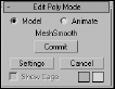
The Commit button lets you freeze the changes and set the keyframe for the current change. The current change is listed directly above the Commit button. The Settings button lets you access the dialog box used to make the changes. The Cancel button cancels the last change, and the Show Cage option displays an orange cage around the object; you can change the color of the cage using the color swatch. The cage is useful when using the MeshSmooth modifier to see the original shape of the object before being smoothed.
The differences between the features available for the Edit Poly modifier and the Editable Poly object are subtle. In the Selection rollout is a Get Stack Selection button. Clicking this button passes the subobject selection up from the stack. Also, the Edit Poly modifier doesn't include the Subdivision Surfaces rollout, but you can use the MeshSmooth modifier to get this functionality.
Edit Geometry Modifiers
Most of the Mesh Editing modifiers are used to change the geometry of objects. Some of these modifiers, such as Extrude and Tessellate, perform the same operation as buttons available for the Editable Mesh or Editable Poly objects. Applying them as modifiers separates the operation from the base geometry.
Cross-Reference
You can find a more general explanation of modifiers in Chapter 11, “Introducing Modifiers and Using the Modifier Stack.”
Cap Holes modifier
The Cap Holes modifier patches any holes found in a geometry object. Sometimes when objects are imported, they are missing faces. This modifier can detect and eliminate these holes by creating a face along open edges.
For example, if a spline is extruded and you don't specify Caps, then the extruded spline has holes at its end. The Cap Holes modifier detects these holes and creates a Cap. Cap Holes parameters include Smooth New Faces, Smooth with Old Faces, and Triangulate Cap. Smooth with Old Faces applies the same smoothing group as that used on the bordering faces.
Delete Mesh modifier
You can use the Delete Mesh modifier to delete mesh subobjects. Subobjects that you can delete include Vertices, Edges, Faces, and Objects. The nice part about the Delete Mesh modifier is that it remains in the Modifier Stack and can be removed to reinstate the deleted subobjects.
The Delete Mesh modifier deletes the current selection as defined by the Mesh Select (or Poly Select) modifier. It can be used to delete a selection of Vertices, Edges, Faces, Polygons, or even the entire mesh if no subobject selection exists. The Delete Mesh modifier has no parameters.
Note
Even if the entire mesh is deleted using the Delete Mesh modifier, the object still remains. To completely delete an object, use the Delete key.
Extrude modifier
The Extrude modifier can be applied only to spline or shape objects, but the resulting extrusion can be a Patch, Mesh, or NURBS object. This modifier copies the spline, moves it a given distance, and connects the two splines to form a 3D shape. Parameters for this modifier include an Amount value, which is the distance to extrude, and the number of segments to use to define the height. The Capping options let you select a Start Cap and/or an End Cap using either a Morph or Grid option. The Morph option divides the caps into long, thin polygons suitable for morph targets, and the Grid option divides the caps into a tight grid of polygons suitable for deformation operations. The Cap fills the spline area and can be made as a Patch, Mesh, or NURBS object. Only closed splines that are extruded can be capped. You can also have mapping coordinates and Material IDs generated automatically. The Smooth option smoothes the extrusion.
Cross-Reference
Chapter 12, “Drawing and Editing 2D Splines and Shapes,” includes a good example of the Extrude modifier.
Face Extrude modifier
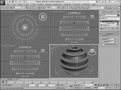
The Face Extrude modifier extrudes the selected faces in the same direction as their normals. Face Extrude parameters include Amount and Scale values and an option to Extrude From Center. Figure 26.7 shows a mesh object with several extruded faces. The Mesh Select modifier was used to select the faces, and the extrude Amount was set to 30.
FIGURE 26.7 Extruded faces are moved in the direction of the face normal.
Tutorial: Extruding a bullet
As a simple example that uses a couple of Mesh modifiers, you'll create a single bullet using a hemisphere object. You can create this simple object in other ways, but this offers some good practice.
To create a bullet using the Face Extrude modifier, follow these steps:
- Select Create
 Standard Primitives Sphere, and drag in the Top viewport to create a sphere object. Set the Radius value to 60 and the Hemisphere value to 0.5 to create half a sphere.
 - Right-click on the sphere object, and select Convert To Editable Poly in the pop-up quadmenu to convert the hemisphere to an Editable Poly object.
- Select the Top viewport, right-click on the viewport name, and select Views Bottom from the pop-up menu (or press the B key) to switch to the Bottom view.
- In the Selection rollout, click the Vertex button to enter Vertex subobject mode and enable the Ignore Backfacing option. Then select the single vertex in the center of the hemisphere, and press the Delete key.
- In the Selection rollout, click the Border button to enter Border subobject mode, and then click the edge of the hemisphere in the Front viewport to select the border of the hole that was created by deleting the center vertex. Then click the Cap button in the Edit Borders rollout.
- Select the Polygon button in the Selection rollout to enter Polygon subobject mode and select the bottom polygon subobject in the Perspective viewport after rotating the object around. Then select Modifiers Mesh Editing Face Extrude to apply the Face Extrude modifier to the selected polygon face. Set the Amount value to 200.
- Select Create Standard Primitives Cylinder, and drag in the Bottom viewport to create a thin Cylinder object that is just wider than the extruded hemisphere. Then move the new Cylinder object until it is positioned at the end of the bullet object.
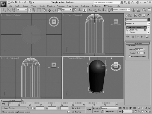
Figure 26.8 shows the completed simple bullet.
FIGURE 26.8 A simple bullet can be created by extruding one face of a hemisphere.
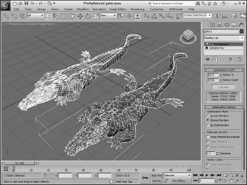
ProOptimizer modifier
Although the latest game consoles are getting much better at handling lots of polygons, sometimes you'll want to reduce a high-resolution model. For example, if you have a high-res statue in your scene, you might want the same statue to be lower-res when used as part of the background. Max offers an excellent modifier that enables you to reduce the total number of polygons in a model while maintaining its shape.
New Feature
The ProOptimizer modifier has been improved in 3ds Max 2012. The modifier is now faster and isn't as likely to flip faces.
When first applied, the ProOptimizer modifier doesn't do anything. To use it, you need to select the settings first and then click the Calculate button. The settings found in the Optimization Options rollouts let you define which vertices can be removed. For example, you can set the optimization to Crunch Borders, Protect Borders, or Exclude Borders. A border is an edge connected to a single face. The Crunch Borders option makes the borders fair game for being optimized. This can yield the greatest amount of reduction but also can change the surface of the model. The Protect Borders option minimizes the amount of reduction at the borders, and the Exclude Borders option removes any border faces from being considered for reduction. The last choice limits the amount of reduction that is possible, but rigidly maintains the surface.
Other settings let you specify the Material Boundaries, Textures, and/or UV Boundaries off-limits. Additional settings protect any applied Vertex Colors and Normals. The Merge tools cause all vertices and/or faces within a given Threshold to be merged before optimizing the mesh. This helps to eliminate any extra vertices or co-planar faces that could cause problems. Finally, the Sub-Object Selection setting lets you preserve a given selection of vertices and makes it possible to optimize only a portion of the model.
The Symmetry options cause the modifier to equally reduce polygons on either side of a designated axis to maintain visual symmetry. There is also a Tolerance value for looking for symmetrical edges. Within the Advanced Options rollout, the Favor Compact Faces resists eliminating a face if it causes sharp pointed faces as a result. You can also select to Prevent Flipped Normals and the Lock Vertex Position option prevents any of the remaining vertices from being moved from their original locations, thus maintaining the model's shape.
After all the settings have been configured, click the Calculate button to run the optimization pass. The Statistics panel (located under the Calculate button) shows the number of points and faces in the model. By dialing down the Vertex % value, you can interactively reduce the total number of faces.
Figure 26.9 shows an alligator model that has been optimized using the ProOptimizer modifier. Notice the dramatic reduction in the number of faces from the left to the right. Viewpoint Datalabs, known for producing high-resolution models, created this model. In the Modify panel, you can see that the number of faces has been reduced from 34,404 to 6,937 faces. (I guess that would make the gator on the right “lean and mean.”)
The Optimize and MultiRes modifiers are older versions of the ProOptimizer modifier and are maintained for compatibility with older files.
If you have an entire folder full of models that you want to optimize, you can use the Batch ProOptimizer utility. This utility is available from the Utilities panel and opens a dialog box where you can specify the source files to optimize, all the optimization settings, and the out filenames and locations. Once configured, you can simply click the Ok button to optimize several model files in a batch process.
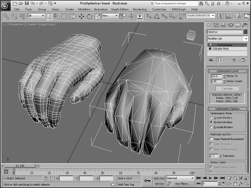
Tutorial: Creating a low-res hand
You can use the ProOptimizer modifier to dynamically dial down the resolution to exactly what you want. In this example, you use the ProOptimizer modifier on a high-res hand model created by Viewpoint Datalabs. The hand weighs in at 2,906 polygons, which is a little heavy for any game engine.
FIGURE 26.9 You can use the ProOptimizer modifier to reduce the complexity of the alligator model.
To create a MultiRes hand, follow these steps:
- Open the ProOptimizer hand.max file from the Chap 26 directory on the CD.
This file contains a simple hand model.
- With the hand selected, choose ProOptimizer from the Modifier List to apply the modifier to the hand model.
- In the Optimization Options rollout, enable the Protect Borders option, the Merge Vertices option with the Threshold to 0.05, and the Merge Faces option with the Threshold set to 0.5. Then click the Calculate button.
- Create a copy of the hand by holding down the Shift key and dragging the hand to the right. In the Clone Options dialog box that appears, select Copy, name the clone Hand – Lo, and click OK.
- With the cloned hand selected, set the Vertex % to 10.
Notice that the number of faces has dropped from over 2,906 to 286.
Figure 26.10 shows the results of the MultiRes modifier. If you look closely, you can see that the hand on the right isn't as smooth, but it still looks pretty good and the game engine won't complain.
Caution
Reducing mesh density on the fly should not be done with animated objects such as characters because the mesh can become chaotic and dirty, resulting in poor deformations. However, the ProOptimizer modifier does work very well with static background objects.
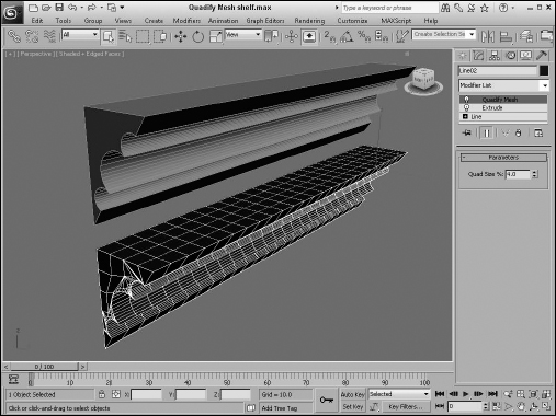
Quadify Mesh modifier
If you look at the individual shape of polygons in most models, you find either a triangle with three sides or a rectangle with four sides. Rectangle polygons are called quads, and they generally are nice to work with because they line up neatly into equal rows and columns. Triangles, on the other hand, flip back and forth even when lined up, making them more difficult to work with.
You can convert quads into triangles in many ways. This can be done in Max using a Triangulate command or modifier. This command simply divides the quads in half, but moving from triangles to quads isn't as easy and takes some clever calculating. But Max has figured it out and made it a feature with the Quadify Mesh modifier.
The single parameter for this modifier is the Quad Size %. Larger values result in bigger and fewer quads, and smaller values increase the number of quads. Figure 26.11 shows a simple shelf that has been quadified.
FIGURE 26.10 You can use the ProOptimizer modifier to dynamically dial back the complexity of a mesh.
Tip
The Quadify Mesh modifier works well with shapes that have been extruded.
Smooth modifier
You can use the Smooth modifier to auto-smooth an object. This automates the creation of different smoothing groups based on the angular threshold. Smooth parameters include options for Auto Smooth and Prevent Indirect Smoothing along with a Threshold value. The Parameters rollout also includes a set of 32 Smoothing Groups buttons labeled 1 through 32. These same Smoothing Groups are available as options for the Polygon and Element subobjects.
Symmetry modifier
The Symmetry modifier allows you to mirror a mesh object across a single axis. You can also select to Slice Along Mirror and weld along the seam with a defined Threshold. The gizmo for this modifier is a plane, which matches the selected axis and the arrow vector that extends from the plane.
FIGURE 26.11 The Quadify Mesh modifier converts the model into regular-shaped quad faces.
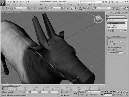
Tutorial: Creating symmetrical antlers
Using symmetry, you can create one half of a model and then use the mirror tool to create the other half. If you need to see the changes as you make them, you can use the Symmetry modifier. In this example, I've taken the antlers off an elk model so you can practice putting them back on.
To create a set of symmetrical antlers, follow these steps:
- Open the Elk with short antlers.max file from the Chap 26 directory on the CD.
This file contains an elk model created by Viewpoint Datalabs with its antlers removed.
- With the elk object selected, select the Modifiers Mesh Editing Symmetry menu command to apply the Symmetry modifier. Its default setting has the X-axis selected, which places a plane running down the center of the elk model, but you need to enable the Flip option so the symmetry goes the right way.
- In the Modifier Stack, select the Editable Poly object and enable the Polygon subobject mode. Then rotate the view until you're looking at the elk from behind its head. Select a polygon on the left side of the elk where the antler should be located.
- In the Edit Polygons rollout, click the option dialog box button for the Bevel tool. Set the Height value to 2.0, the Outline Amount to −0.15, and click OK.
- With the polygon still selected, move the beveled polygon outward away from the elk's head.
- Disable the polygon subobject mode and click on the Symmetry modifier in the Modifier Stack to see the symmetrical antler.
Tip
If you toggle the Show End Result button in the Modifier Stack, then you can see the results of the Symmetry modifier in real time.
Figure 26.12 shows the results of the Symmetry modifier.
FIGURE 26.12 When you use the Symmetry modifier, you have to model certain objects only once.
Tessellate modifier
You use the Tessellate modifier to subdivide the selected faces for higher-resolution models. You can apply tessellation to either Triangle or Polygonal faces. The Edge option creates new faces by dividing the face from the face center to the middle of the edges. The Face-Center option divides each face from the face center to the corners of the face. The Tension setting determines whether the faces are convex or concave. The Iterations setting is the number of times the modifier is applied.
Caution
Applying the Tessellate modifier to an object with a high Iterations value produces objects with many times the original number of faces.
Vertex Weld modifier
The Vertex Weld modifier is a simple modifier that welds all vertices within a certain Threshold value. This is a convenient modifier for cleaning up mesh objects.
Miscellaneous Modifiers
Several of the Mesh Editing modifiers are unique, special-purpose modifiers. The Edit Normals modifier, for example, lets you change the direction of face normals, which doesn't really change the geometry, but it can have a big impact on how the object is smoothed and shaded.
Edit Normals
The Edit Normals modifier enables you to select and move normals. Normals appear as blue lines that extend from the vertex of each face. The Edit Normal modifier includes a Normals subobject that you can select and change its direction. To move (or rotate) a normal, you can use the transform tools on the main toolbar. If your viewport has shading enabled, you can see the effect of moving the normals.
Tip
The Edit Normals modifier can be used to create the illusion of surface geometry. For example, by selecting and flipping specific localized normals, you can create what look like dents in a metal plate.
You can select normals by Normal, Edge, Vertex, or Face. Selecting normals by Face, for example, selects all normals attached to a face when you click on a face. Moving a normal then moves all selected normals together.
You also have options to Ignore Backfacing and to Show Handles. Handles appear as small squares at the top of the normal vector. The Display Length value defines the length of the normals displayed in the viewports. Figure 26.13 shows all the normals extending from a simple Sphere object.
FIGURE 26.13 The Edit Normals parameters let you work with normals.

The modifier also includes buttons to Unify and to Break selected normals. Unify causes all selected normals to be combined to a single normal, and Break splits unified normals into their separate components again. The direction of the unified normal is an average of the surface points when unified or an average of the normals if the Unify/Break to Average option is enabled.
The Selected button in the Average section averages all selected normals that are within the specified value if the Use Threshold value is enabled. If it is not enabled, then all selected normals are averaged. The Average Target button lets you interactively select a normal and then click on another normal to average. The Target normal must be within the specified Target value.
The direction of selected normals can be copied and pasted between normals. The Specify button marks a normal as a Specified normal. These normals appear cyan in the viewport and ignore any smoothing group information associated with the vertex. Explicit normals are green in the viewport, which denotes a normal that has deviated from its regular position. The Make Explicit button can be used to make normals explicit, thereby removing them from the normal computation task. The Reset button returns a normal to its regular type and position. At the bottom of the Parameters rollout is an information line that displays which normal is selected or how many normals are selected.
Normal modifier
The Normal modifier is the precursor to the Edit Normals modifier. It enables object normals to be flipped or unified. When some objects are imported, their normals can become erratic, producing holes in the geometry. By unifying and flipping the normals, you can restore an object's consistency. This modifier includes only two options: Unify Normals and Flip Normals.
STL Check modifier
The STL Check modifier checks a model in preparation for exporting it to the StereoLithography (STL) format. STL files require a closed surface: Geometry with holes or gaps can cause problems. Any problems are reported in the Status area of the Parameters rollout.
This modifier can check for several common errors, including Open Edge, Double Face, Spike, or Multiple Edge. Spikes are island faces with only one connected edge. You can select any or all of these options. If found, you can have the modifier select the problem Edges or Faces, or neither, or you can change the Material ID of the problem area.
Subdivision Surface Modifiers
The Modifiers menu also includes a submenu of modifiers for subdividing surfaces. These include the MeshSmooth and HSDS Modifiers. You can use these modifiers to smooth and subdivide the surface of an object. Subdividing a surface increases the resolution of the object, allowing for more detailed modeling.
MeshSmooth modifier
The MeshSmooth modifier smoothes the entire surface of an object by applying a chamfer function to both vertices and edges at the same time. This modifier has the greatest effect on sharp corners and edges. With this modifier, you can create a NURMS object. NURMS stands for Non-Uniform Rational MeshSmooth. NURMS can weight each control point. The Parameters rollout includes three MeshSmooth types: Classic, NURMS, and Quad Output. You can set it to operate on triangular or polygonal faces. Smoothing parameters include Strength and Relax values.
Settings for the number of Subdivision Iterations to run and controls for weighting selected control points are also available. Update Options can be set to Always, When Rendering, and Manually using the Update button. You can also select and work with either Vertex or Edge subobjects. These subobjects give you local control over the MeshSmooth object. Included within the Local Control rollout is a Crease value, which is available in Edge subobject mode. Selecting an Edge subobject and applying a 1.0 value causes a hard edge to be retained while the rest of the object is smoothed. The MeshSmooth modifier also makes the Soft Selection rollout available. The Reset rollout is included to quickly reset any crease and weight values.
TurboSmooth modifier
The TurboSmooth modifier works just like the MeshSmooth modifier, except that it is much faster and doesn't require as much memory.
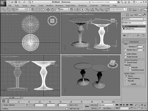
Tutorial: Smoothing a birdbath
One effective way to model is to block out the details of a model using the Editable Poly features and then smooth the resulting model using the TurboSmooth modifier. This gives the model a polished look and increases the resolution.
To create a smoothed birdbath object, follow these steps:
- Open the Birdbath.max file from the Chap 26 directory on the CD.
This file includes a simple birdbath created by selecting and scaling rows of cylinder vertices. The water is simply an inverted cone.
- Select and clone the existing birdbath as an instance by pressing the Shift key and moving the birdbath.
- Select the cloned birdbath, and apply the TurboSmooth modifier with the Modifiers Subdivision Surfaces TurboSmooth menu.
- In the TurboSmooth rollout, set the Iterations value to 2.
Notice that the entire birdbath is smooth and the resolution is greatly increased, as shown in Figure 26.14.
HSDS modifier
You use the HSDS (Hierarchical SubDivision Surfaces) modifier to increase the resolution and smoothing of a localized area. It works like the Tessellate modifier, except that it can work with small subobject sections instead of the entire object surface. The HSDS modifier lets you work with Vertex, Edge, Polygon, and Element subobjects. After a subobject area is selected, you can click the Subdivide button to subdivide the area. Each time you press the Subdivide button, the selected subobjects are subdivided again, and each subdivision level appears in the list above the Subdivide button.
Using the subdivision list, you can move back and forth between the various subdivision hierarchy levels. When edges are selected, you can specify a Crease value to maintain sharp edges. In the Advanced Options rollout, you can select to Smooth Result, Hide, or Delete Polygon. The Adaptive Subdivision button opens the Adaptive Subdivision dialog box, in which you can specify the detail parameters. This modifier also includes a Soft Selection rollout.
FIGURE 26.14 The TurboSmooth modifier can make a model flow better.
Summary
The Paint Deformation feature is a welcome addition, allowing you to add surface details using an intuitive and easy-to-use interface. Max includes several unique modifiers that apply specifically to mesh objects. This chapter covered these topics:
- Using the various Paint Deformation brushes
- Setting brush options with the Painter Options dialog box
- How the Edit Mesh and Edit Poly modifiers can be used to edit a primitive object using the Editable Mesh and Editable Poly features while maintaining its parametric nature
- How several mesh modifiers are used to edit surface geometry
- How to edit normals and what the effects are
- Working with the Subdivision Surface modifiers to smooth mesh objects
The next chapter focuses on working with a miscellaneous group of mutant objects called compound objects. These objects are unique and used for special purposes.