
BONUS CHAPTER 14
Quick Start—3ds Max 7 Bible: Creating and Animating a Three-Fingered Gaaboot
Introducing and planning the Quick Start project
Modeling the Gaaboot character
Adding scene landscape objects
Applying materials
Loading a background image
Creating a biped
Attaching skin to the biped
Animating a character
Rendering the final animation
When you first got your hands on 3ds max, you were probably focused on one goal—creating cool 3D images and animations. I know that many of you bought Max to make money, claim a tax write-off, earn a way to Hollywood, or impress your girlfriend or boyfriend, but I—ll just ignore those reasons for now. The goal is to create something cool.
If you've perused this book's Table of Contents or thumbed through its many pages, you've seen sections on modeling, NURBS, dynamics, and other topics. But if you're like me, you don't want to wade through tons of material before you have something to show off to Mom. (Actually, if you're like me, then you've opened straight to the special effects section, in which case you won't be reading this.)
The purpose of this Quick Start is to give you a taste of what Max can do. This soaring view of the software from 20,000 feet is intended to show you the big picture before you delve into the details. It exposes you to the most common features—including many new ones—and whets your appetite for the more in-depth chapters to follow.
This part of the book is intended for those new to the software. If you're an experienced user, then your mom no doubt is already impressed with your work, so you can happily advance to whichever chapter appeals to you. (Forgive me for catering to the newbie, but we were all beginners once.)
Visiting an Alien World—Planning the Production
As a creative genius, no doubt you've imagined many alien worlds inhabited by odd-looking beings. These imaginations are perfect fodder for creating worlds in Max. The latest world I've imagined is the distant planet of Boogaloot inhabited by an annoyingly happy race of aliens called the Gaaboot.
This Quick Start walks you through creating a Gaaboot alien and his simple world landscape, attaching it to a biped, and animating it using Character Studio. That's quite a tall order depending on the complexity involved, but we'll keep everything pretty simple.
Before diving in, the proper method is to start with a plan, including a simple sketch of the Gaaboot character. The only thing we know about the Gaaboot race is that they have three fingers, which probably means they have three toes also.
After completing a rough sketch, I can see that the Gaaboot character is dumpy with large jowls and a pleasant disposition. I also realize that the character has a nice symmetry that I can use to model only half of the character and mirror to get the other half. The folds of the skin are smooth, which makes me think I can rough out the character as an Editable Poly object and apply a TurboSmooth modifier to smooth all the edges.
For the landscape, I imagine something that's rather bare like the moon, so a plane object with a single crater or two should do it. A space background would be a nice touch.
For materials, the Gaaboot character is green, of course, and the planet surface is a grayish, dusty, rocky texture. The Gaaboot is completely naked, so applying extra materials to cover the character isn't necessary, but without shoes, you need to model extra details like toes.
To animate the character, we use a biped skeleton, which makes the task of animating a snap, but the trick is resizing the biped and making sure the envelopes cover the entire character.
For the animation, we simply have the Gaaboot walk forward and wave to the visitors.
With a definite plan, we're ready to begin. This Quick Start is divided into separate tutorials, with each tutorial containing a series of easy-to-follow steps. These steps are intended to show you the results of performing certain Max operations, but feel free to deviate from these steps to create your own results. Being creative and exploring the software is the best way to learn.
On the CD-ROM
After each of the following tutorials, I saved the scene file. You can find these files in the Bonus Chapter 14 directory on the book's CD.
Modeling the Main Character
The first step in the production is to model the main character—our friendly neighborhood Gaaboot. The modeling process is divided into four simple tutorials. In the first one, you create the head and body objects by modifying primitive objects. The second tutorial focuses on creating the hands and feet by adjusting subobjects and using a modifier. The third tutorial focuses on the details of the face, and the final tutorial creates arms and legs using borders and the Bridge feature.
The following tutorials show one character modeling technique, but many others exist. As you explore the various modeling techniques, find and develop methods that work well for you.
Tutorial: Modeling the Gaaboot—s body and head
Our first step begins the task of modeling the main character. We start with the two major elements of the character: the head and the body. The details and smoothing come later; for now, we only want to get the basic shape.
To create the Gaaboot's body and head, follow these steps:
- Select Create
 Standard Primitives GeoSphere, and drag in the Top viewport to create a GeoSphere object with a Radius of about 120. In the Name and Color rollout of the command panel, name this object body.
Note
This chapter uses Generic Units. You can change the units using the Units Setup dialog box opened using the Customize
Units Setup menu command. - Right-click the GeoSphere object, and select the Convert To Convert to Editable Poly menu command from the pop-up quadmenu.
- In the Modifier Stack, select the Vertex subobject mode and drag over the centermost vertices in the Top viewport. This selects vertices on both sides of the sphere. Open the Soft Selection rollout, enable the Use Soft Selection option, and set the Falloff value to 150 and the Pinch value to 1.0. Drag the selected vertices upward in the Left viewport with the Move tool to create a raindrop-like object. Click the Vertex subobject in the Modifier Stack to exit Vertex subobject mode.
- Select the Scale tool, and drag the Y-axis handle upward in the Left viewport to scale the body object's height. Then drag the Y-axis downward in the Top viewport to scale the depth of the character.
- Select the Create Shapes Line menu command, and in the Front viewport, click to place the points to create an outline of the head. Right-click after the final point to exit point placement mode.
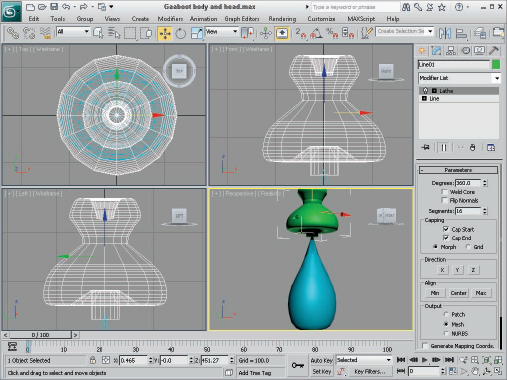
- With the Line object selected, open the Modify panel and enable Vertex subobject mode. Use the Move tool to straighten any misplaced vertices. Select the Modifiers Patch/Spline Editing Lathe menu command to revolve the line to create a 3D object. In the Parameters rollout, select the Y Direction and the Min Align buttons. You also may need to enable the Flip Normals option to correctly see the head object.
- With the lathed object selected, enter head in the Name field. Move and scale the head object until it fits just above without touching the top of the body object.
- With the body object selected, click the Attach button in the Edit Geometry rollout and select the head object.
This attaches the head as an element to the body object and converts it into an Editable Poly.
The result of this tutorial, shown in Figure 1, doesn't look like a valid character, but it provides a good starting point that you can enhance with details like a face, arms, and legs. This tutorial is saved on the CD as Gaaboot body and head.max.
FIGURE 1 The head and body of the Gaaboot character were constructed from simple primitives.
Tutorial: Modeling the Gaaboot—s hands and feet
Gaaboot anatomy is still largely a mystery, but we know something about how the hands should look: They have three fingers.
To create the Gaaboot's hands and feet, follow these steps:
- Select Create Standard Primitives Cylinder, and drag in the Front viewport to the left side of the body object to create a Cylinder object with a Radius of about 40 and a Height of around 30. Set the Height and CapSegments values to 1 and the Sides value to 24. In the Name field, name this object r_hand.
- Right-click the Cylinder object, and select the Convert To Convert to Editable Poly menu command from the pop-up quadmenu.
- Use the Scale tool to stretch the hand object's width in the Front viewport by dragging the X-axis handle.
- In the Modifier Stack, select Vertex subobject mode, press and hold the Ctrl key, and drag over the vertices in the 8 o'clock and 10 o'clock positions. In the Soft Selection rollout, set the Falloff value to 20 and the Pinch value to 0.0. Drag the selected vertices to the right in the Front viewport with the Move tool, and use the Scale tool to pull the vertices closer together to create three fingers. Click the Vertex subobject in the Modifier Stack to exit Vertex subobject mode.
- Select the Modifiers Parametric Deformers Taper menu command to apply the Taper modifier. Set the Taper amount to 2.0 with the X Primary axis and a Z Effect axis.
This tapers the hand to a point at the end of the middle finger.
- Press and hold the Shift key, and move the hand object downward in the Front viewport to create a clone of the hand object. In the Clone Options dialog box that opens, name the new object r_foot and select the Copy option. Rotate the foot object 90 degrees in the Y- and Z-axes, move it down below the character, and scale it to be larger than the hand.
Don't worry that the hand and foot are free standing like the head. We connect them soon enough, and we use the mirror command to make the character not so one-sided, but the result of this tutorial is shown in Figure 2. This tutorial is saved on the CD as Gaaboot hands and feet.max.
FIGURE 2 The Gaaboot character with one hand and one foot

Tutorial: Adding face details
Now that some of the major body parts are finished, you start to add details, beginning with the face. Face details include eyes, a nose, and a mouth. We skip ears because Gaaboots listen by using their feet to pick up vibrations in the ground. This is a design decision that helps simplify the modeling process—a valid trick if you're also the designer.
To add details to the Gaaboot's face, follow these steps:
- Select the head and body object, and enable Polygon subobject mode by clicking Polygon in the top of the Modifier Stack. In the Soft Selection rollout, disable the Use Soft Selection option. Enable the Ignore Backfacing option in the Selection rollout, and drag over just the top flared section of the head in the Front viewport. Press and hold the Alt key, and drag over the polygons that aren't visible from the front in the Top viewport. Then click the Y-axis button next to the Make Planar button in the Edit Geometry rollout.
- In the Edit Geometry rollout, click the Cut button. Use the Cut tool in the Front viewport to cut the edges needed to create a mouth opening. Right-click when you're finished cutting, and click the Cut button again to exit cut mode. While still in Polygon subobject mode, press and hold the Ctrl key, and select all the polygons on the interior of the mouth.
- With the mouth polygons selected, click the Options dialog box button next to the Bevel button in the Edit Polygons rollout. In the Bevel Polygons dialog box, set the Height value to −20 and the Outline Amount to −0.5, and click the OK button. Then click the Polygon subobject button to exit subobject mode.
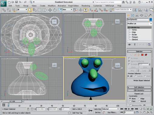
- Select the Create Standard Primitives GeoSphere menu command, and drag at the top of the head in the Front viewport to create an eyeball. Name the sphere eyeball. Move the eyeball to the front of the face. Press and hold the Shift key, and drag the sphere to the side to create another eyeball. Name this object eyeball2, and select the Instance option in the Clone Options dialog box.
- Clone one of the eyeball objects with the Edit Clone command, but don't make it an Instance; make it a Copy, and name it nose. Then elongate the nose object with the Scale tool. Rotate and position the nose so it's above the top of the center of the face.
With the face details added, the character shown in Figure 3 is starting to look like someone who would speak back to you when spoken to. Even more details are added using textures—details such as pupils created using vertex colors. This tutorial is saved on the CD as Gaaboot face.max.
Tutorial: Connecting body parts
The final modeling task is to pull all the various body parts together. The easiest way to accomplish this is to cut holes in each part, select the borders of each hole, and connect them using the Bridge feature.
To connect the various Gaaboot body parts, follow these steps:
- Select the head and body object, and enable Polygon subobject mode. Rotate the view under the head in the Perspective view until the base at the bottom of the head is visible, and select and delete these polygons. Then select and delete all the polygons that make up the very top of the body object.
- In the Modifier Stack, choose Border subobject mode and drag over the bottom of the head and the top of the body to select the two open border subobjects. Click the Bridge button in the Edit Borders rollout to seamlessly connect the two parts.
- Right-click the hand object, and select the Convert To Convert to Editable Poly menu command from the pop-up quadmenu. Convert the foot object also.
FIGURE 3 The face details give the character some life and an orientation.
- Change to Perspective view to see the portion of the hand that is near the body. Switch to Polygon subobject mode, and select and delete the polygons where the hand should connect to the arm.
- Select the foot object, and use the Cut tool to cut a polygon in the top of the foot away from the foot sides. Right-click when you've finished with the Cut tool. Select and delete these polygons in Polygon subobject mode.
- With holes cut in the hand and foot objects, select the hand object and choose the Tools Mirror menu command. In the Mirror dialog box, select the X and Copy options and set the Offset to 750. Repeat this step for the foot object using an Offset value of 195.
- With the body object selected, click the Attach button and pick the hands and feet. Zoom in on the Left viewport, and use the Cut tool to create a hole in the body for the left arm. Select and delete those polygons. Click the Left viewport title in the upper-left corner, select Views Right to change the viewport to the Right viewport, and repeat Step 6 to cut a hole. After a hole is cut in the right side, enable the Vertex subobject mode, and select and drag the hole vertices down to be roughly aligned with the hole vertices on the opposite side. Select the Top viewport, change it to a Bottom view, and cut two holes for the legs.
- Select the Border subobject mode, and select the body hole and the hand hole on the right side. Click the Options box button next to the Bridge tool in the Edit Borders rollout. Set the number of Segments to 6, and click the OK button. Select the borders for the opposite arm and click the Bridge button. Repeat for both legs.
- The final part to attach is the nose. Follow the same procedure using cut, attach, select borders, and bridge to connect the nose.
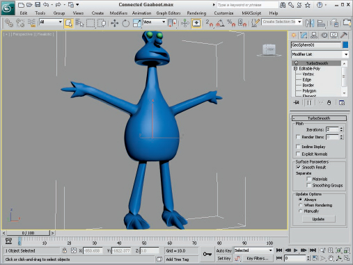
- As a final step to smooth all the sharp edges throughout the character, select the Modifiers Subdivision Surfaces TurboSmooth menu command. In the TurboSmooth rollout, set the number of Iterations to 2.
This applies the TurboSmooth modifier, which gives the whole model an organic feel.
Caution
The TurboSmooth modifier also increases the density of the mesh substantially. If you need to make future modeling changes, select the Editable Poly below TurboSmooth in the Modifier Stack before making any changes.
At the completion of this tutorial, the Gaaboot finally has arms and legs and looks, well, like an alien, as shown in Figure 4. This tutorial is saved on the CD as Connected Gaaboot.max.
FIGURE 4 The Gaaboot modeling is now finished and despite the brevity of the steps, it looks pretty good.
Creating the Landscape
Before animating the character, we create a simple landscape for the character to walk about. The landscape helps define the character's environment and provides some stationary objects to make the character's motion more apparent.
The tutorials in this section include creating a lunar-like surface complete with several craters and adding a backdrop image.
Tutorial: Creating a lunar surface
A lunar surface can be easily created using a Plane primitive object that extends to the horizon. The craters can be separate objects that rise from the surface of the plane object.
Another detail that helps the scene is adding a background image. To do this, use the Environment & Effects dialog box opened with the Rendering ![]() Environment menu command (or by pressing the 8 keyboard shortcut).
Environment menu command (or by pressing the 8 keyboard shortcut).
To create a lunar surface, follow these steps:
- Zoom out of the Top viewport, select the Create Standard Primitives Plane menu command, and drag in the Top viewport to create a large Plane object that extends far beyond the Gaaboot character. Select and move the Gaaboot character so its feet are just slightly above the Plane object.
- Select the Create Standard Primitives Box menu command, and drag in the Top viewport behind and to the side of the character. Set the dimensions of the box to 1500 × 1500 × −10 with 24 Length and Width Segments and only 1 Height Segment.
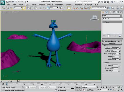
- Select the Create Space Warps Geometric/Deformable Ripple menu command, and drag in the Top viewport in the center of the Box object. Set the Amplitude 1 and 2 values to −750 and −150, the Wave Length value to 700, the Phase to 0.5, and the Decay value to 0.002. Select the Box object, click the Bind to Space Warp button on the main toolbar, and select the Ripple Space Warp gizmo in the viewport.
- Select the Box object, and choose the Modifiers Parametric Deformers Noise menu command to apply the Noise modifier. In the Parameters rollout, enable the Fractal option, and set the Roughness to 0.7 and the Strength in the Z-axis to 60.
- Drag over the box and Space Warp in the Top viewport to select them both, press and hold the Shift key, and drag the box and Space Warp to another location surrounding the character. Rotate the box object for some variation. Repeat this step to create a third crater.
The simple craters help the scene by showing some depth, and the Noise modifier adds some much needed richness, as shown in Figure 5. This tutorial is saved on the CD as Gaaboot with landscape.max.
FIGURE 5 The Gaaboot world, complete with craters, is beginning to take shape.
Tutorial: Loading a background image
To inform the user that the scene is out in space, we add a space scene as a background image.
To add a background image to the scene, follow these steps:
- Open the Environment & Effects dialog box by choosing Rendering Environment (or by pressing the 8 key). Enable the Use Map check box, and click the Environment Map button labeled None.
The Material/Map Browser dialog box appears.
- In the right pane of the Material/Map Browser where a list of materials and maps appears, double-click the Bitmap item found in the Maps rollout.
The Select Bitmap Image File dialog box opens.
- Locate the background image named Space.tif in the Bonus Chapter 14 directory on the CD, and click it to select it.
- Click Open to load the background image. When loaded, the image's filename appears on the button in the Environment panel. Click the close icon in the upper-right corner of the Environment dialog box to close it.
- To see the background image in a test render, select the Rendering Rendered Frame Window.
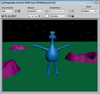
Figure 6 shows the test render in the Rendered Frame Window with the visible space background. This tutorial is saved on the CD as Gaaboot with background.max.
FIGURE 6 The background image adds to the alien scene.
Adding Materials to Objects in the Scene
After you have all the models positioned within the scene, you can add realism by adding materials to objects. Materials are created and applied using the Material Editor. Open this separate dialog box with the Rendering ![]() Material Editor menu command (or by pressing the M shortcut).
Material Editor menu command (or by pressing the M shortcut).
Another way to add color to the scene is at the vertex level with Vertex Colors using the Vertex Paint Modifier, which works well for adding pupils to the character's eyeballs.
Tutorial: Applying materials
The default object color doesn't do our Gaaboot justice, and the lunar surface looks all wrong, but adding materials will help.
To apply materials to the scene objects, follow these steps:
- To assign materials, you must open the Material Editor. You can do this by choosing the Rendering Material Editor menu command or by pressing the M key.
The Material Editor shows six sphere objects. These are called sample slots, and they can be used to hold materials used in the scene.
- With the first sample slot in the Material Editor selected, click the color swatch to the right of the Diffuse label in the Blinn Basic Parameters rollout. This opens the Color Selector dialog box. Select a dark green color, and click the Close button. Scroll down in the Command Panel, and set the Specular Level value to 95 and the Glossiness value to 50. Click in the drop-down list where it says 01–Default, and type Eyeball as the name of this material.
- Select the sample slot in the Material Editor directly under the first one, and click the small square map button to the right of the color swatch that is right of the Diffuse label. This opens the Material/Map Browser dialog box. Double-click the Speckle material. In the Speckle Parameters rollout, click the Color #2 color and change it to a dark green color, and set the Size value to 40. Name this material Gaaboot skin. Open the Maps rollout, and click the button labeled None next to the Bump map. In the Material/Map Browser that appears, double-click the Cellular map type. Although the Cellular map isn't visible in the viewports, it gives the skin a nice rough texture when rendered.
- Select another empty sample slot, change its Diffuse color to a light brown color, and name the material Sand. Select the Cellular map type for the Bump map. The procedure is the same as for the Gaaboot skin material, but this time set the Size value in the Cellular Parameters rollout to 50. After setting the sub-material, click the Go to Parent button to return to the base sand material.
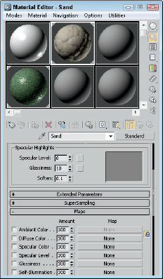
The Material Editor should now look like Figure 7.
FIGURE 7 The Material Editor now includes three unique materials that you can use in the scene.
- To apply the materials to the scene, just drag each respective material to the object in the viewport that it goes with.
Tip
If you want to see the material textures in the viewport, click the small cube button labeled Show Map in Viewport in the Material Editor.
Aw, you can't beat that slick green alien skin color with black spots. I hope it isn't contagious. Because the figures in this bonus Quick Start are black and white, you can't see much change between this result and the last image, so look on your monitor. This tutorial is saved as Gaaboot with materials.max.
Tutorial: Adding eye pupils using vertex colors
The Gaaboot looks great with its new materials, but its eyes still have that look like some spaceship is shining a bright light right in its eyes. In this tutorial, you add pupils to the eyeballs using vertex colors.
To use vertex colors to add pupils to the character, follow these steps:
- Select the Perspective viewport, and click the Maximize Viewport Toggle button in the lower-right corner of the Max interface (or press Alt+W). Rotate the view by pressing and holding the Alt key and dragging with the middle mouse button so you're looking directly at the eyeballs. Then zoom in on the eyes using the Zoom tool or by scrolling the mouse wheel.
- Select one of the eyeballs, and choose the Modifiers Mesh Editing Vertex Paint menu command. In the VertexPaint dialog box that opens, click the Vertex Color Display–shaded button at the top of the dialog box. Set the Brush Size to 2.0, and select black as the color. Click the Paintbrush button, and drag around the center of the eyeball.
- Select the other eyeball object and click the Vertex Color Display–shaded button. The second eyeball already has the same vertex coloring.
- For the Vertex Colors to be rendered correctly, you need to include them on a map that is assigned to the object. To do this, open the Compact Material Editor again and select the Eyeball material. Click the map button to the right of the Diffuse color swatch, and double-click the Vertex Color map type in the Material/Map Browser that appears.
After you reapply the Eyeball material to the eyeball object, the painted pupils appear when rendered.
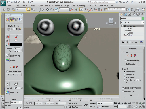
This simple addition of eyeball pupils, shown in Figure 8, helps the character seem more realistic, and it didn't require any geometry changes or creating a new material. This tutorial is saved on the CD as Gaaboot with eye pupils.max.
FIGURE 8 Adding pupils to the eyes gives some life to the character.
Animating a Character
Character animation can be a difficult aspect of a production, but the Character Studio tools make it much easier, especially for animations involving walking and running human (or even alien!) forms.
The tutorials for this section include creating a biped, attaching a character skin using the Physique modifier, and animating the biped. A biped is a skeleton structure that exists beneath the character. It consists of bones that can be animated easily in lifelike manners, deforming the overlaid skin in the process.
Tutorial: Creating and fitting a biped
The first step in using Character Studio is creating and manipulating a biped skeleton. The closer you can make the biped fit the character, the less work is required to manipulate envelopes. Each bone has an envelope that surrounds it. All the skin vertices that are contained within a bone's envelope move along with the bone. If any skin vertices aren't included in an envelope, the vertices are left behind when the biped moves.
Note
Fitting the bones to the skin takes much more time than all the other steps, but diligence in completing this step results in a skin that matches the biped perfectly. The skin won't need any other modifications.
To create and fit a biped to the character skin, follow these steps:
- First, hide all the objects that you don't need to see. Select the character, right-click, and select the Hide Unselected menu command from the pop-up quadmenu.
All objects except the skin are hidden.
- Select the Create Systems Biped menu command, and drag in the Top viewport to create a biped that is the same height as the character and positioned directly behind the character. In the Create Biped rollout, set the number of Neck Links to 5. (Gaaboots have serious necks.)
- Open the Motion panel, and click the Figure Mode button in the Biped rollout to enter Figure mode. Select the lower leg bone in the Left viewport, click the Symmetrical button in the Track Selection rollout to select both lower leg bones, and scale the bones in the Y-axis to shorten them. Repeat this step for the upper legs. Select the Body Vertical button in the Track Selection rollout, and drag the entire body downward until the pelvis bone is in the correct position.
- Select both upper leg bones again, and use the Rotate tool to rotate the bones to align with the character skin legs in the Front viewport. Repeat for the upper arm bones. Make the arms parallel to the skin arms, but they shouldn't match up just yet.
- Open the Structure rollout, and reduce the number of Spine Links to 3. Select all three spine links, and scale them along the Y-axis in the Left viewport until they are correctly aligned with the skin arms. Select all five neck links, and scale them along the Y-axis in the Left viewport until the head bone is aligned with the skin head.
- Select the Front viewport, and change it to show the Back view. Then start with the head bone, and scale it horizontally to fit the width of the skin. Continue down the skeleton with each bone until they are scaled to roughly fit the skin. Be careful with the top spine and the pelvis bones because the arms and legs are attached to these bones.
- Move up and down the arms and legs, scaling them to fit the skin arms and legs. The hand bones in particular must be rotated to fit the skin, and the feet need to be scaled in length as well as width.
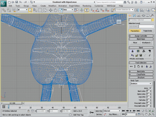
Figure 9 shows the resulting skin with the biped bones aligned within it. The effort put into aligning bones is apparent in the next tutorial when we attach the skin to the biped. This tutorial is saved on the CD as Gaaboot with biped.max.
FIGURE 9 Notice how closely the biped bones are aligned with the skin.
Tutorial: Attaching the character skin to a biped
This next step sounds like it should be easy enough, but depending on how complex the skin mesh is and how well you've aligned the biped bones, this could be the hardest step.
To attach a character skin to a biped, follow these steps:
- Select the character skin mesh, and choose the Modifiers Parametric Deformers Physique menu command to apply the Physique modifier to the skin mesh.
- In the Physique rollout, click the Attach to Node button. Open the Select Objects dialog box, and choose the Bip01 object, which is the root for the biped. In the Physique Initialization dialog box that opens, click the Initialize button.
- Using the Select Objects dialog box, select and rotate several bones (including both arms and legs) to check whether all vertices are moving correctly.
If any vertices aren't within an envelope, the skin stretches as the bone is moved.
- To fix any vertices that are outside an envelope, follow this step. In the Modifier Stack, click the Physique modifier to access its subobjects and select Envelope subobject mode. Select the left hand link, click the Cross Section button in the Blending Envelopes rollout, and resize the two sections so all vertices are within the outer envelope. Click the Control Points button in the Blending Envelopes rollout, and move the control points to control the shape of the envelope so it includes only the vertices you want.
- To select another link, click the Links button in the Blending Envelopes rollout and click the Previous button to select the previous link in the hierarchy. Increase the Radial Scale value to increase all cross sections and control points at once.
If all vertices are accounted for, then you're ready to animate the character using the biped controls found in the Motion panel. This tutorial is saved on the CD as Gaaboot with attached skin.max.
Tutorial: Animating a character's motion
For the animation sequence, we don't get very complex; we simply use the biped's Footstep modeto have the character walk across the lunar surface, but it shows the power of the biped animation features.
To animate a character walking, follow these steps:
- Before moving the skin, unhide all objects by right-clicking the viewport and selecting the Unhide All option. Select the Gaaboot skin object, and select the Editable Poly entry in the Modifier Stack. Click the Options button next to the Attach button, and select both eyeball objects from the Attach List dialog box. In the Attach Options dialog box, choose Match Material IDs to Material to maintain the applied materials. You need to see all the hidden objects, so you may want to hide the skin mesh to see the biped clearly. Select the skin mesh, and choose Hide Selection from the quadmenu.
- Press T to switch to the Top viewport, and zoom out until the biped and all three craters are visible. Drag the biped to the center of the screen.
- With the biped selected, open the Motion panel and click the Footstep Mode button in the Biped rollout to enter Footstep mode. In the Footstep Creation rollout, select the Walk button and click the Create Multiple Footsteps button to open the Create Multiple Footsteps: Walk dialog box. Enter 25 as the Number of Footsteps, and click OK.
When the Create Multiple Footsteps dialog box first opens, it automatically determines the correct stride length for the given biped.
- Select and rotate the first several steps so the character walks in front of the top crater before turning to point in the right direction.
- Click the Create Keys for Inactive Footsteps button in the Footstep Operations rollout to create keys for the available footsteps.
- Click the Play Animation button to see the biped walk across the surface.
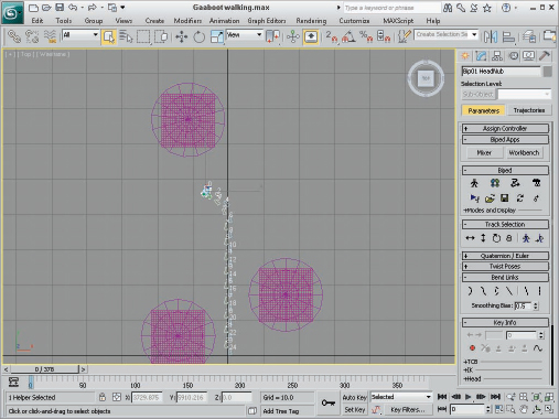
Figure 10 shows the footsteps taken by the character in the Top viewport. This tutorial is saved on the CD as Gaaboot walking.max.
FIGURE 10 Animating the character is as easy as making it follow the designated footsteps.
Rendering the Final Animation
Rendering the final animation can take lots of time, depending on the output resolution and the power of your computer. The final output is started through the Render Scene dialog box, which you can open with the Rendering ![]() Render menu command (or by pressing the F10 key). The Render Scene dialog box offers several options for customizing the output. But before rendering the final output, you should create a preview animation to make sure everything looks okay.
Render menu command (or by pressing the F10 key). The Render Scene dialog box offers several options for customizing the output. But before rendering the final output, you should create a preview animation to make sure everything looks okay.
Tutorial: Creating a preview animation
Before rendering the final scene, we should produce a Preview animation. Doing so helps to eliminate some problems before time is spent rendering the entire animation. The Preview is simply the viewport scene stitched together into an animation. The shading options are the same as those available for the viewports.
To create a Preview animation, follow these steps:
- Right-click the viewport, and select Unhide All from the quadmenu. Select and hide all the biped bones. With the Perspective viewport active, choose Animation Make Preview.
- In the Make Preview dialog box, you can select the Active Time Segment, which includes all frames in the animation. Set the Image Size to 50 percent, and select the AVI Output option. In the Display in Preview section, make sure to check the Geometry and Background check boxes. Select Perspective as the Render Viewport.
- Click the Create button.
Max begins the rendering, opens the default Media Player when finished, and plays the preview.
- Choose Animation View Preview to view the preview again, if desired.
As you look at the preview, notice that the material maps aren't included in the preview, but you can watch for the following types of errors:
- Objects moving through one another
- Insufficient lighting
- Erratic (non-smooth) object motion
Tutorial: Rendering the final animation
After you've fixed all the errors and you're comfortable with the Preview animation, you can open the Render Scene dialog box and prepare your final animation for rendering.
To view the final animation rendering settings, follow these steps:
- Open the Render Scene dialog box by choosing Rendering Render (or by pressing F10).
- In the Time Output section, select Active Time Segment. In the Output Size section, select 320×240 as the resolution.
- Save the rendered scene to a file. In the Render Output section, click the Files button to open the Render Output File dialog box. Select the location where you want to save the file; enter the name Gaaboot walking; and from the Save as type drop-down list, select .AVI as the format. Click Save.
Tip
If you don't want to save the file, you can render the scene to the Rendered Frame Window. After the rendering is complete, you can save the animation by clicking the Save Bitmap button. The Rendered Frame Window can save to both animation and bitmap formats.
The Video Compression dialog box appears.
- Select the Cinepak Codec by Radius Compressor with a Quality setting of 100 and a Key Frame every 15 frames. Click OK to continue.
- Back in the Render Scene dialog box, check the viewport setting at the bottom of the dialog box and make sure Perspective is selected. Click the Render button to start the rendering process.
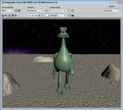
Figure 11 shows a frame from the final animation. This final tutorial is saved as Final render.max.
FIGURE 11 One frame from the final animation of our friendly three-fingered Gaaboot walking across the lunar surface
We could do much more to this animation, such as using lens effects or adding a motion blur, but I wanted to save some effects for the rest of the book. Feel free to load and modify this simple animation as you desire.
Summary
I hope you're happy with your first footsteps into Max. This chapter exposed you to a number of important aspects of Max, including the following:
- An approach to modeling characters
- Applying materials to scene objects
- Loading a background image for the scene
- Creating, fitting, and attaching a biped to a character skin
- Animating a character
- Rendering a preview and the final animation
But hold onto your seats because so much of the software lies ahead. In Chapter 1, you start easily with an in-depth look at the Max interface. If you feel ready for more advanced challenges, review the Table of Contents and dive into any topic that looks good.