
When you first got your hands on 3ds Max, you were probably focused on one goal—creating cool 3D images and animations. I know that many of you bought Max to make money, claim a tax write-off, earn a way to Hollywood, or impress your girlfriend or boyfriend, but I'll just ignore those reasons for now. The goal is to create something cool.
If you've perused this book's Table of Contents or thumbed through its many pages, you've seen sections on modeling, materials, dynamics, and other topics. But if you're like me, you don't want to wade through tons of material before you have something to show off to Mom. (Actually, if you're like me, then you've opened straight to the special effects section, in which case you won't be reading this.)
The purpose of this Quick Start is to give you a taste of what Max can do. This soaring view of the software from 20,000 feet is intended to show you the big picture before you delve into the details. It exposes you to some of the most common features and hopefully whets your appetite for the more in-depth chapters to follow.
This part of the book is intended for those new to the software. If you're an experienced user, then your mom no doubt is already impressed with your work, so you can happily advance to whichever chapter appeals to you. (Forgive me for catering to the "newbie," but we were all beginners once.)
For this Quick Start, you're going to fire a cannon. This will give you a chance to model a cannon (but the cannonball should be easy enough), animate the shot, and use fire and particle effects.
If you first consider the modeling of the scene, you'll need a cannon that can fire the cannonball. Most of your cannon can be built from primitive objects, but you don't want to get involved in too many details so you'll keep it fairly simple. Although you have a good idea of what a cannon looks like, it is helpful to download some reference images of the Web that you can look at while modeling.
Note
Most images you find in books and magazines or on the Web are copyrighted, so be aware of the licensing before deciding to use an image you find online. However, images can be used to generate ideas and as references as long as you create an original object.
You'll also need a ground plane that you can use to give the scene some perspective. You'll also want to include a sky background. For materials, you'll use some realistic materials created in the Material Editor using the ProMaterials.
For the animation phase, you'll need to animate not only the cannonball traveling across the countryside, but also all the recoil of the cannon. Here again, video references are helpful if you can find one. You'll also want to use particles to come out of the cannon when fired.
Finally, for lighting you'll want to use a lighting model that works well for outdoor scenes, so the Daylight system will work well.
Note
After each of the following tutorials, I saved the scene file. You can find these files in the Quick Start directory on the book's DVD.
The modeling process is divided into several simple tutorials. The first step in the production is to model the cannon. One of the simplest cannons I found as a reference image on the Web is from an old Civil War cannon. This cannon includes wooden wheels on either side connected by an axle. The following tutorials show one modeling technique, but many others exist. As you explore the various modeling techniques, find and develop methods that work well for you.
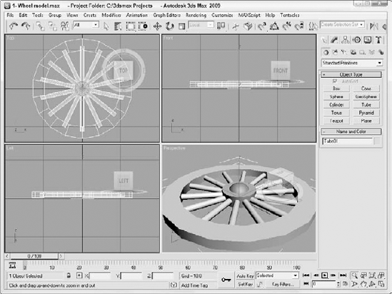
Your first step begins with the task of modeling a single cannon wheel. You'll then clone the wheel and move it to the opposite side, and then connect the two wheels with an axle. Then, you'll add the barrel and the support.
To create a cannon model, follow these steps:
Start by resetting the interface with the File

Before modeling the first wheel, turn on the Snaps Toggle in the main toolbar so that all created points will snap to the grid points. Configure the Snaps figure by right-clicking the Snaps Toggle button. This opens the Grid and Snap Settings dialog box. Make sure the Grid Points option is selected, and close the dialog box.
Select Create
Note
This chapter uses Generic Units. You can change the units using the Units Setup dialog box, which you open using the Customize
Select Create
Tip
Given the cylindrical spokes won't be changing shape, there is no reason to have the Height Segments set to more than 1. By keeping unnecessary polygons out of the model, you can keep the complexity manageable.
With the cylinder selected, choose the Tools
The spokes all meet and overlap in the center of the wheel, so you'll create a cylinder to overlay the center of the spokes. Select the Create
To add some variety to the center hub, select the Create
The first wheel is now complete, as shown in Figure QS.1.
With the first wheel finished, you'll create a clone of it and position the second wheel, but you'll want to temporarily group the wheel so all the pieces move together.
To group, clone, and position all the wheels, follow these steps:
Select the Edit
Enable the Angle Snap button on the main toolbar and rotate the wheel in the Top viewport 90 degrees so it is standing upright.
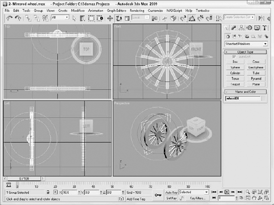
Although you can clone objects by moving them with the Shift key let down, you want to keep the sphere on the outside of the wheel, so you'll want to mirror the wheel. Select the Tools
Click the Zoom Extents All button in the lower-right corner to see both wheels in all viewports.
Both wheels are now positioned, as shown in Figure QS.2.
With the wheels in place, you can complete the cannon by adding the axle, the barrel, and the support.
To finish the cannon model, follow these steps:
Using the Front viewport, select the Create
With the axle selected, select the Tools
In the Left viewport, select the Create
Select the barrel object and choose the Modifiers
In the Left viewport, select the Create
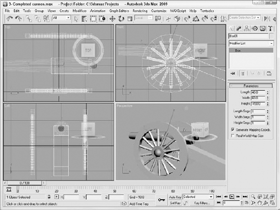
In the Left viewport, select the Create
The cannon is now complete, as shown in Figure QS.3, and ready for the next steps of applying materials.
After the modeling is complete, you can add materials to the objects to improve their look. Materials are added using the Material Editor, which is opened using the Rendering
Max includes a special set of materials that are used to dress up buildings and architectural designs, but they require that the mental ray render engine be enabled. After the mental ray render engine is enabled using the Render Scene dialog box, you can access the ProMaterials materials in the Material Editor.
To add materials to the cannon, follow these steps:
Select the Rendering
Select the Rendering
In the Metal Material Parameters rollout at the top of the Material Editor, select the Anodized Aluminum option from the Type drop-down list. Then click on the Color (Reflectance) color swatch and change the color to black. Then drag the Metal material from its sample slot in the Material Editor, and drop it on the barrel and back-end objects.
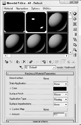
Select the second sample slot, and repeat the preceding step to choose the ProMaterials: Hardwood material with a black color. Then select the barrel and back-end objects and choose the Edit
With materials applied to the Greek temple, the objects in the viewport will look different, but you can't see a rendered view until you add some lights to the scene.
Another benefit of having the mental ray renderer enabled is that you also can use the Sun & Sky system. This system simulates outdoor lighting from a distant source like the sun and generates a sky for the background and a ground plane also.
To add a Sun & Sky system to the scene, follow these steps:
Because the Sun & Sky system adds a ground plane to the scene, you need to reposition the cannon so it is located above the default grid plane. Use the Edit
Select the Create
Note
When the Daylight System is applied, a dialog box automatically appears recommending that you use the Logarithmic Exposure Control and asks if you want to make this change. Click Yes to continue.
Select the Render
Next, choose the Views
Then click the Maximize Viewport button (Alt+W) in the lower-right corner of the interface to make the Perspective viewport full sized.
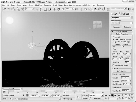
With the daylight selected, click the Setup button in the Daylight Parameters rollout found in the Modify panel. Then set the Time Hours to 18. This sets the time of day to sundown and places the sun in the horizon.
The viewport now shows the cannon with a background sky and a ground plane, as shown in Figure QS.5.
Before moving to animation, you can render the scene now that lights have been added. Rendering is configured using the Render Scene dialog box.
To render the cannon scene, follow these steps:
Use the viewport navigation controls, located in the lower-right corner of the interface, to position the cannon view just the way you like it.
Select the Rendering
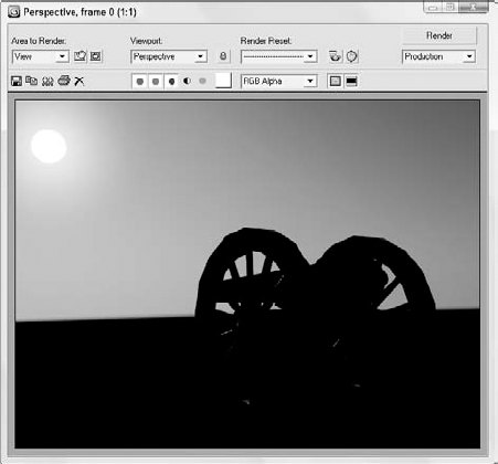
Back in the Common panel of the Render Scene dialog box, select the image size in the Common Parameters rollout and click the Render button. The active viewport automatically is rendered and displayed in the Render Frame Window.
The rendered cannon image, as shown in Figure QS.6, includes all the materials, lighting effects, reflections, and refractions.
After the scene is looking good, you can work on animating the firing a cannonball. First you need to create a cannonball and apply the same material used on the barrel.
To fire a cannonball, follow these steps:
Click the Maximize Viewport toggle button in the lower-right corner of the interface to toggle back to four viewports. Then zoom out of the Top viewport so you can see the entire cannon and the distant horizon.
Select the Create
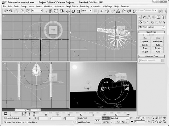
Drag the Time Slider to frame 10 and click the Auto Key button at the bottom of the interface. Then click the Key button to create a keyframe for the cannonball.
Drag the Time Slider to frame 20 and drag the cannonball forward away from the cannon until it is out of the scene. The cannonball should only be visible for 4 frames as it moves out of the scene.
Drag over all the objects that make up the cannon object in the Front viewport and drag the Time Slider to frame 10 again.
Click the Key button to create an initial keyframe for the cannon. Then drag the Time Slider to frame 13 and move the cannon backwards to define the recoil. With AutoKey enabled, the keyframe is created automatically.
Select just the barrel and the back end and return the Time Slider to frame 10; then click the Key button to set a key. Drag the Time Slider to frame 13 and rotate the barrel about 5 degrees upward. Then drag the Time Slider to frame 16 and rotate the barrel back to its original position. By adding the secondary motion to the barrel, the animation looks more real.
Tip
Remember to turn off the Auto Key button when you are done animating or you will continue to create keys as you edit the scene.
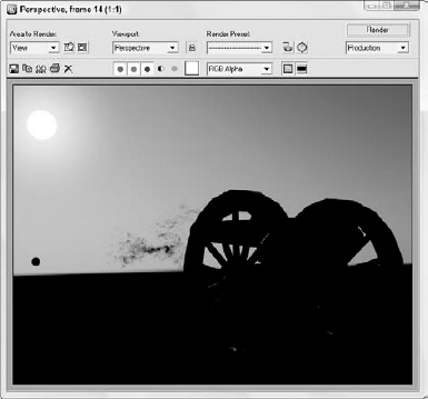
Figure QS.7 shows one frame of the animation as the cannonball is leaving the cannon. Using the Render Scene dialog box, you can render the entire animation, or you can use the Animation
As a final effect to the scene, you'll add a stream of particles that will be emitted as the cannonball emerges. This effect also helps with the realism of the scene.
To add a particle effect to the scene, follow these steps:
Select the Create
Choose the Select and Link button on the main toolbar and drag from the particle system icon to the cannon barrel. This links the particle system to the barrel so that it moves with it.
In the Modify panel, set the Off Axis and Off Plane Spread values to 30 to cause the particles to fan out from its initial location. In the Particle Generation rollout, set the Use Total amount to 10000, the Speed to 30, the Emit Start to 8, the Emit Stop to 20, and the Life to 30 with a Variation of 40. Then set the Particle Size to 20 with a Variation of 20.
Open the Material Editor and select the third sample slot; then click in the small map box to the right of the Diffuse Color and choose the Particle Age map. Then set Color1 to orange, Color2 to yellow, and Color3 to black.
Then click the Up arrow icon in the Material Editor to get back to the base material and click the map button for the Opacity parameter and select the Smoke map in the Material/Map Browser. This will make the material semi-transparent and wispy.
Apply the new material to the particle system.
Figure QS.8 shows the frame after particles have been added to the system.
I hope you're happy with your first footsteps into Max. This chapter exposed you to a number of important aspects of Max, including the following:
An approach to modeling using primitives
Applying ProMaterials materials to different scene objects
Using the Sun & Sky system and enabling lights and shadows in the viewport
Animating the cannon using keyframes
Adding a particle system to the scene
But hold onto your seats, because so much of the software lies ahead. In Chapter 1, you start easily with an in-depth look at the Max interface. If you feel ready for more advanced challenges, review the Table of Contents and dive into any topic that looks good.