

z/Architecture and addressing
z/Architecture is the next step in the evolution from System/360 to System/370, System/370 Extended Architecture (370-XA), Enterprise Systems Architecture/370* (ESA/370),and Enterprise Systems Architecture/390 (ESA/390). In order to understand z/Architecture you have to be familiar also with the basics of ESA/390 and its predecessors.
An address space maps all of the available addresses, and includes system code and data as well as user code and data. Thus, not all of the mapped addresses are available for user code and data. This limit on user applications was a major reason for System/370 Extended Architecture (370-XA) and MVS/XA. Because the effective length of an address field expanded from 24 bits to 31 bits, the size of an address space expanded from 16 megabytes to 2 gigabytes. An MVS/XA address space is 128 times as big as an MVS/370 address space.
This chapter describes:
•Program status word (PSW)
•Address space addressability
•Dumps in 31-bit and 64-bit modes
10.1 Program status word (PSW)

Figure 10-1 Program status word (PSW)
Program status word
One very important piece of information that will be crucial to your ability to diagnose a problem on z/OS is the program status word, more commonly referred to as the PSW. The PSW includes the instruction address, condition code, and other information to control instruction sequencing and to determine the state of the CPU. The active or controlling PSW is called the current PSW.
The PSW is so important because it keeps track of the progress of the system and the executing program. The current PSW usually points to the address of the next instruction to be executed. In some specific cases the PSW will point to the address of the failing instruction and this occurs when the interrupt code is 0010, which is a segment translation exception, or interrupt code 0011, which is a page translation exception.
What this means is that when a task abends and a dump is taken, the PSW is pointing to the next instruction that will be executed in the failing program. By subtracting the instruction-length code (ILC) from the PSW address, we will be looking at the failing instruction for which the abend was triggered.
|
Note: For page translation and segment translation errors, the PSW points to the failing instruction.
|
10.2 Program-status word (PSW)

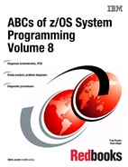
Figure 10-2 Program Status Word (PSW)
Current PSW
The current PSW is a storage circuit located within the CP. It contains information required for the execution of the currently active program, or, in other words, it contains the current state of a CP. It has 16 bytes (128 bits). The PSW includes the instruction address, condition code, and other information used to control instruction sequencing and to determine the state of the CP. The active or controlling PSW is called the current PSW. It governs the program currently being executed. Figure 10-2 describes the PSW from bits 0 to 127.
PER mask - R (bit 1)
Bit 1 controls whether the CP is enabled for interrupts associated with program-event recording (PER). When the bit is zero, no PER event can cause an interruption. When the bit is one, interruptions are permitted, subject to the PER-event-mask bits in control register 9.
DAT mode - T (bit 5)
Bit 5 controls whether implicit dynamic address translation of logical and instruction addresses used to access storage takes place. When the bit is zero, DAT is off, and logical and instruction addresses are treated as real addresses. When the bit is one, DAT is on, and the dynamic-address-translation mechanism is invoked.
I/O mask - IO (bit 6)
Bit 6 controls whether the CP is enabled for I/O interruptions. When the bit is zero, an I/O interruption cannot occur. When the bit is one, I/O interruptions are subject to the I/O-interruption subclass-mask bits in control register 6. When an I/O-interruption subclass-mask bit is zero, an I/O interruption for that I/O-interruption subclass cannot occur; when the I/O-interruption subclass-mask bit is one, an I/O interruption for that I/O-interruption subclass can occur.
External mask - EX (bit 7)
Bit 7 controls whether the CP is enabled for interruption by conditions included in the external class. When the bit is zero, an external interruption cannot occur. When the bit is one, an external interruption is subject to the corresponding external subclass-mask bits in control register 0; when the subclass-mask bit is zero, conditions associated with the subclass cannot cause an interruption; when the subclass-mask bit is one, an interruption in that subclass can occur.
PSW key (bits 8-11)
Bits 8-11 form the access key for storage references by the CP. If the reference is subject to key-controlled protection, the PSW key is matched with a storage key when information is stored or when information is fetched from a location that is protected against fetching. However, for one of the operands of each of MOVE TO PRIMARY, MOVE TO SECONDARY, MOVE WITH KEY, MOVE WITH SOURCE KEY, and MOVE WITH DESTINATION KEY, an access key specified as an operand is used instead of the PSW key.
Machine-check mask - M (bit 13)
Bit 13 controls whether the CP is enabled for interruption by machine-check conditions. When the bit is zero, a machine-check interruption cannot occur. When the bit is one, machine-check interruptions due to system damage and instruction-processing damage are permitted, but interruptions due to other machine-check-subclass conditions are subject to the subclass-mask bits in control register 14.
Wait state - W (bit 14)
When bit 14 is one, the CP is waiting; that is, no instructions are processed by the CP, but interruptions may take place. When bit 14 is zero, instruction fetching and execution occur in the normal manner. The wait indicator is on when the bit is one. When in a wait state, the only way of getting out of that state is through an interruption, or IPL (a z/OS boot). Certain bits in the current PSW, when off, place the CP in a disabled state, that is, it does not accept interrupts. So, when z/OS because of any error reason (software or hardware) decides to stop a CP, it sets the PSW in a disabled and wait state, forcing an IPL as the way to get the CP back in a running state.
Problem state - P (bit 15)
When bit 15 is one, the CP is in the problem state. When bit 15 is zero, the CP is in the supervisor state. In the supervisor state, all instructions are valid. In the problem state, only those instructions are valid that provide meaningful information to the problem program and that cannot affect system integrity; such instructions are called unprivileged instructions. The instructions that are never valid in the problem state are called privileged instructions. When a CP in the problem state attempts to execute a privileged instruction, a privileged-operation exception is recognized. Another group of instructions, called semiprivileged instructions, are executed by a CP in the problem state only if specific authority tests are met; otherwise, a privileged-operation exception or a special-operation exception is recognized.
Address-space control -AS (bits 16-17)
Bits 16 and 17, in conjunction with PSW bit 5, control the translation mode.
Condition code - CC (bits 18-19)
Bits 18 and 19 are the two bits of the condition code. The condition code is set to 0, 1, 2, or 3, depending on the result obtained in executing certain instructions. Most arithmetic and logical operations, as well as some other operations, set the condition code. The instruction BRANCH ON CONDITION can specify any selection of the condition code values as a criterion for branching.
The part of the CP that executes instructions is called the arithmetic logic unit (ALU). The ALU has four internal bits that are set by certain instructions. At the end of such instructions this 4-bit configuration is mapped into bits 18 and 19 of the current PSW.
As an example, the instruction COMPARE establishes a comparison between two operands. The result of the comparison is placed in the CC of the current PSW, as follows:
•CC=00, the operands are equal
•CC=01, the first operand is lower
•CC=10, the first operand is greater
To test the contents of a CC (set by a previous instruction), use the BRANCH ON CONDITION (BC) instruction. It has an address of another instruction (branch address) to be executed depending on the comparison of the CC and a mask M. The instruction address in the current PSW is replaced by the branch address, if the condition code has one of the values specified by M; otherwise a normal instruction sequencing proceeds with the normal updated instruction address. Here are the types of codes:
•Condition code - bits 18 and 19 of the PSW
•Return code - a code associated with how a program ended
•Completion code - a code associated with how a task ended
•Reason code - a code passed in GPR 15, giving more details about how a task ended
Program Mask (bits 20-23)
During the execution of an arithmetic instruction, the CP may find some unusual (or error) condition, such as: overflows, loss of significance, underflow. In these cases, the CP generates a program interrupt. When this interrupt is treated by z/OS, usually the current task is abnormally ended (abend). However, in certain situations the programmer does not want an abend, so through the instruction SET PROGRAM MASK (SPM), he or she can mask such interrupts by setting to off some of the program mask bits. Each bit is associated with one type of condition:
•Fixed point overflow (bit 20)
•Decimal overflow (bit 21)
•Exponent underflow (bit 22)
•Significance (bit 23)
Observe that the active program is informed about the above events through the condition code posted by the instruction where the events described happened.
The contents of the CP can be totally changed by two events:
•Loading a new PSW from storage along an interruption
•Executing the instruction LPSW, which copies 128 bits from memory to the current PSW.
Extended addressing mode - EA, BA (bits 31-32)
The combination of bits 31 and 32 specify the addressing mode (24, 31, or 64) of the running program. Bit 31 controls the size of effective addresses and effective address generation in conjunction with bit 32, the basic addressing mode bit. When bit 31 is zero, the addressing mode is controlled by bit 32. When bits 31 and 32 are both one, 64-bit addressing is specified.
10.3 64-bit addressing
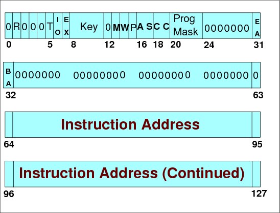
Figure 10-3 64-bit addressing
What is addressability
One of the major developments of the MVS operating system was the implementation of 31-bit addressing. Prior to MVS/XA the highest virtual storage location that could be addressed was 16 megabytes, or hexadecimal FFFFFF. Actually, it was one byte less that 16 megabytes, because we start at zero. As applications grew larger the 24-bit architecture limitations were recognized, and 31-bit addressability was introduced. The 31-bit standard increased the amount of addressable virtual storage to 2 gigabytes. The addressing mode of a program is determined by the high order bit (bit 32 of the PSW) of the instruction address. If this bit is set to 1 the processor is running in 31-bit mode. If it is 0 then the processor is running in 24-bit mode.
We have now taken the next step in storage addressability with z/OS, implementing 64-bit addressing. This means that the maximum storage that can be addressed is 2 ** 64, or 16 exabytes. The highest address when running in 64-bit mode is X’FFFFFFFF_FFFFFFFF’ as opposed to the previous 31-bit high address of X’7FFFFFFF’.
Format of the PSW
Prior to z/OS and 64-bit mode operations, the PSW was 64 bits in length and comprised of two 32-bit words. The first 32 bits (identified as bits 0 through 31) related to system state and mode status, but the second 32 bits (identified as bits 32 through 63 as shown in Figure 10-4 on page 264) indicated the addressing mode in the first bit and the address of the next instruction in bits 33 through 63. The second word is what will interest us in most cases, as shown in Figure 10-3.
For example,
PSW: 075C2000 82CC5BCC Instruction length: 02
Instruction address (bits 64 to 127)
Bits 64 to 127, shown in Figure 10-3 on page 262, point to the storage address of the next instruction to be executed by this CP. When an instruction is fetched from main storage, its length is automatically added to this field. It then points to the next instruction address. However, there are instructions such as a BRANCH that may replace the contents of this field, pointing to the branched instruction. The address contained in this PSW field may have 24, 31, or 64 bits, depending on the addressing mode attribute of the executing program. For compatibility reasons, old programs that use small addresses are still allowed to execute. When in 24- or 31-bit addressing mode, the leftmost bits of this field are filled with zeroes.
CP interrupts
The CP has an interrupt capability, which permits it to switch rapidly to another program in response to exceptional conditions and external stimuli. When an interrupt occurs, the CP places the current PSW in an assigned storage location, called the old-PSW location, for the particular class of interrupt. The CP fetches a new PSW from a second assigned storage location. This new PSW determines the next program to be executed. When it has finished processing the interrupt, the program handling the interrupt may reload the old PSW, making it again the current PSW, so that the interrupted program can continue.
There are six classes of interrupt: external, I/O, machine check, program, restart, and supervisor call. Each class has a distinct pair of old-PSW and new-PSW locations permanently assigned in real storage.
10.4 Next sequential instruction
Figure 10-4 Next sequential instruction address
PSW second word
Using the PSW, example:
PSW: 075C2000 82CC5BCC Instruction length: 02
The second word of the PSW is 82CC5BCC. The first number, 8, indicates that this program is executing in 31-bit mode. In other words, this program runs above the 16-megabyte line. The number 8 in binary is 1000, which indicates the addressing mode bit 32 is ON. A value of zero decimal would be binary zero, 0000, indicating that the addressing mode bit 32 is OFF, which identifies that this location was below the 16-bit line, or in 24-bit mode.
The remaining data points to the next instruction to be executed. In this case, 2CC5BCC. For the sake of correctness the full address would be 02CC5BCC.
Subtracting the instruction length value, in this case, 2, from the PSW address, would result in 02CC5BCA, which would point to the failing instruction.
The PSW has now changed and the z/OS 128-bit PSW is converted by MVS to a 64-bit double word and the z/OS-formatted PSW is stored in control blocks. The PSW is represented as follows:
AMODE 24
07850000 00000000 00000000 00065788 078D0000 00065788
AMODE 31
04041000 80000000 00000000 00FE5768 040C1000 80FE5768
AMODE 64
04045001 80000000 00000000 01685B28 040C5001_81685B28
The bold form of the PSW indicates the “converted” z/OS PSW. The underscore between the two words of the converted PSW indicates that this is a 64-bit (above the bar) address.
As you can see, it looks similar to the 31-bit PSW except for the non-zero value of bit 31 in the 1st word of the PSW, 040C5001, as well as the non-zero value in bit 32 of the PSW, which is the 1st bit of the second word, 81685B28. It is the use of bits 31 and 32 that indicates this is a 64-bit address. The address to interrogate in this case would be 1_81685B28.
In many cases, for most current applications, you will still be interrogating 31-bit storage addresses, but in the future, as more applications make use of the extended addressability, you will reference storage pointed to by the Addressing Mode (AMODE) 64-bit PSW.
10.5 64-bit address space

Figure 10-5 64-bit address space map
64-bit address space
With z/OS, the MVS address space expands to a size so vast that we need new terms to describe it. Each address space, called a 64-bit address space, is 16 exabytes in size; an exabyte is slightly more than one billion gigabytes. The new address space has logically 264 addresses. It is 8 billion times the size of the former 2-gigabyte address space that logically has 231 addresses. The number is 16 with 18 zeros after it:
16,000,000,000,000,000,000 bytes, or 16 exabytes
If you are coding a new program that needs to store large amounts of data, a 64-bit address space might work for you.
Introduction of 64-bit address space
As of z/OS V1R2, the address space begins at address 0 and ends at 16 exabytes, an incomprehensibly high address. The architecture that creates this address space provides 64-bit addresses. The address space structure below the 2-gigabyte address has not changed; all programs in AMODE 24 and AMODE 31 continue to run without change. In some fundamental ways, the address space is much the same as the XA address space.
In the previous 31-bit address space, a virtual line marks the 16-megabyte address. The 64-bit address space also includes the virtual line at the 16-megabyte address; additionally, it includes a second virtual line called the bar that marks the 2-gigabyte address.
The bar
The bar separates storage below the 2-gigabyte address, called below the bar, from storage above the 2-gigabyte address, called above the bar. The area above the bar is intended for data; no programs run above the bar. There is no area above the bar that is common to all address spaces, and no system control blocks exist above the bar. IBM reserves an area of storage above the bar for special uses to be developed in the future.
Memory sharing
Before z/OS V1R3, all programs in AMODE 31 or AMODE 24 were unable to work with data above the bar. To use virtual storage above the bar, a program must request storage above the bar, be in AMODE 64, and use the new z/Architecture assembler instructions.
As of z/OS V1R5, the following enhancements for 64-bit virtual storage have been added:
•64-bit shared memory support
•Default shared memory addressing area between 2 terabytes and 512 terabytes
This shared memory is used by z/OS UNIX applications.
Using memory above the bar
The reason why someone designing an application would want to use the area above the bar is simple: the program needs more virtual storage than the first 2-gigabyte address space provides. Before z/OS V1R2, a program's need for storage beyond what the former 2-gigabyte address space provided was sometimes met by creating one or more data spaces or hiperspaces and then designing a memory management schema to keep track of the data in those spaces. Sometimes programs written before z/OS V1R2 used complex algorithms to manage storage, reallocate and reuse areas, and check storage availability. With the 16-exabyte address space, these kinds of programming complexities are unnecessary. A program can potentially have as much virtual storage as it needs, while containing the data within the program's primary or home address space.
Virtual memory above 2 GB is organized as memory objects that a program creates. A memory object is a contiguous range of virtual addresses that are allocated by programs as a number of application pages which are 1 MB multiples on a 1 MB boundary. Programs continue to run and execute in the first 2 GB of the address space.
Dynamic address translation
Dynamic address translation is the process of translating a virtual address during a storage reference into the corresponding real address. The virtual address may be a primary virtual address, secondary virtual address, AR-specified virtual address, or home virtual address. These addresses are translated by means of the primary, the secondary, an AR-specified, or the home address-space-control element, respectively.
After selection of the appropriate address-space-control element, the translation process is the same for all of the four types of virtual address. An address-space-control element may be a segment-table designation specifying a 2-GB address space, a region-table designation specifying a 4-TB, 8-PB, or 16-EB space, or a real-space designation specifying a 16-EB space. The letters K, M, G, T, P, and E represent kilo, 2¹0, mega, 2²0, giga, 2³0, tera, 240, peta, 250, and exa, 260, respectively. A segment-table designation or region-table designation causes translation to be performed by means of tables established by the operating system in real or absolute storage. A real-space designation causes the virtual address simply to be treated as a real address, without the use of tables in storage.
Is a dump 31-bit or 64-bit?
The easiest way to determine this is to use ISPF to browse the unformatted dump data set.
The header for each record in the dump will show DR1 for a system running in 31-bit mode and DR2 for a 64-bit system dump. Figure 10-6 shows an ISPF browse of the dump data set.
|
BROWSE APSG.SC48TS.DUMP1
Command ===>
****************************
DR2 H ......................
DR2 CV......................
DR2 CV...................]°.
DR2 CV...................]µ.
DR2 CV...................]^.
DR2 CV...................]{.
|
Figure 10-6 64-bit architecture dump header record
A slightly more complex method for those familiar with IPCS is as follows:
•31-bit (2 GB) MVS address spaces have architected Prefix Save Areas starting at x'0' in low core. These start with the restart new PSW (which begins “040C...”). This is what you would expect to see in low core of dumps from systems that are not running on the new HW, or which are using the new 64-bit support hardware, but are not running in 64-bit mode.
•If an MVS image has been IPLed to exploit 64-bit architecture, the low core will look completely different. The PSA is now 2 KB in size, rather than 1 KB and the format of the PSA starting from x'0' is completely different. Only a few of the fields are retained (for compatibility purposes), for example, the CVT address, the current TCB address and current ASCB address.
•To quickly identify whether a dump was taken from an image exploiting the 64-bit architecture you can look at offset x'A3'. If the value x'01' is set, this dump comes from an MVS image running in 64-bit mode. If x'00' is set, it is running in 31-bit mode. Currently no other bits are used in this byte.
It must be said that apart from the historical significance, you will not see many non-64 bit dumps in most current z/OS environments.
..................Content has been hidden....................
You can't read the all page of ebook, please click here login for view all page.