
Chapter 6: Chaos Engineering with AWS Fault Injection Simulator
This chapter covers the concept of chaos engineering and when it is needed. It will walk you through the principle of chaos engineering and give insights in terms of where chaos engineering fits in concerning Continuous Integration (CI) / Continuous Delivery/Deployment (CD). We will implement chaos action on EC2 instances, the Relational Database Service (RDS), and the Elastic Container Service for Kubernetes (EKS) worker node group via the AWS Fault Injection Simulator, and verify whether the infrastructure is fault-tolerant and the application still responsive. Performing this experiment will give you sufficient confidence to place this as part of CI/CD in your organization.
In this chapter, we are going to cover the following main topics:
- The concept of, and need for, chaos engineering
- Chaos engineering in CI/CD
- Experimenting with AWS FIS on multiple EC2 instances with a terminate action
- Experimenting with AWS FIS on EC2 instances with a CPU stress action
- Experimenting with AWS FIS on RDS with a reboot and failover action
- Experimenting with AWS FIS on an EKS cluster worker node
Technical requirements
To get started, you will require an AWS account and admin-level privileges in that account because we will be interacting with IAM services. You will also find the necessary source code used in this chapter in the chapter-06-nodejsrestapi and chapter-06-starkapp folder of the https://github.com/PacktPublishing/Accelerating-DevSecOps-on-AWS.git.
The concept of, and need for, chaos engineering
In the past, or still somewhere within the finance industry, software systems used to run in an on-premises or controlled environment with the help of an army of system administrators. Today, in the era of the cloud, migration to the cloud is relentless. Software systems are no longer monolithic but uncoupled in the form of microservices. The new and advanced distributed modern IT infrastructure requires robust systems thinking and reliability engineering to ensure that systems are always up and running. Downtime is no longer an option and may impact businesses. To make sure that these systems don't fail or increase the resiliency of these systems, the discipline of chaos engineering emerged.
This is how the chaos community defines chaos engineering:
Chaos engineering is not a new concept. Engineers think that it was introduced by Netflix in 2010, while there was the concept of Game Day in Amazon in 2000 before any big retail sale. Engineers used to simulate data center failure and test that systems were still up and running. In 2010, Netflix introduced the Fault Injection Testing chaos engineering framework, which resulted in disruption to, and the failure of, the distributed system where your application was running. Tools such as Chaos Monkey and Chaos Kong are famous fault injection testing tools. However, chaos engineering doesn't only mean injecting faults into the system; it's a process that is explained in its principles.
Principles of chaos engineering
The whole purpose of chaos engineering is to plan an experiment that shows us how our systems behave during failure and how we can make the system resilient:
- Plan an experiment: You create a hypothesis based on the steady behavior of the system and how it will behave if something goes wrong.
- Contain the blast radius: You create a real-word scenario experiment and test it on the system.
- Scale or squash: You measure the impact of the failure at every stage and look for signs of failure and success.
You can create fault injection simulation by writing your own script using Bash or any programming language of your choice. AWS has introduced an amazing, fully managed chaos engineering service called AWS Fault Injection Simulator (AWS FIS)
AWS FIS
AWS FIS is a managed chaos engineering service that enables you to perform fault injection experiments on your AWS workloads. It provides an automated set of actions that invokes the API to perform certain operations. In this chapter, we will learn how to perform fault injection experiments on the AWS workloads using FIS, but before that, let's understand some of the terminology used in FIS:
- Experiment template: An experiment template includes a blueprint of your experiments. It contains the actions, target, and stop conditions for the experiment. Once you have created an experiment template, you can start the experiment and track its status.
- Actions: An action is a task or activity that AWS FIS applies to AWS resources during the experiment. Actions can run sequentially or in parallel. Currently, AWS FIS provides the following actions:
- aws:fis:inject-api-internal-error
- aws:fis:inject-api-throttle-error
- aws:fis:inject-api-unavailable-error
- aws:fis:wait
- aws:cloudwatch:assert-alarm-state
- aws:ec2:send-spot-instance-interruptions
- aws:ec2:reboot-instances
- aws:ec2:stop-instances
- aws:ec2:terminate-instances
- aws:ecs:drain-container-instances
- aws:eks:terminate-nodegroup-instance
- aws:rds:failover-db-cluster
- aws:rds:reboot-db-instances
- aws:ssm:send-command
- aws:ssm:start-automation-execution
- Targets: A target is one or more AWS resources on which AWS FIS will perform the actions within the framework of the experiment. Currently, AWS FIS supports the following target AWS resources.
- Amazon Elastic Compute Cloud (Amazon EC2)
- Amazon Elastic Container Service (Amazon ECS)
- Amazon Elastic Kubernetes Service (Amazon EKS)
- Amazon Relational Database Service (Amazon RDS)
AWS FIS provides the chaos service using a console as well as a CLI. In the next section of this chapter, we will learn about the stage of CI/CD when chaos testing fits.
Chaos engineering in CI/CD
Chaos tests in CI/CD are well designed, carefully scripted, and automated tests that execute in runtime during the CI/CD process. They are triggered any time after the build all the way through to deployment in production
Chaos testing can be incorporated once the application has been deployed in staging and after the application has been deployed in production. The following diagram shows the chaos test steps in CI/CD:
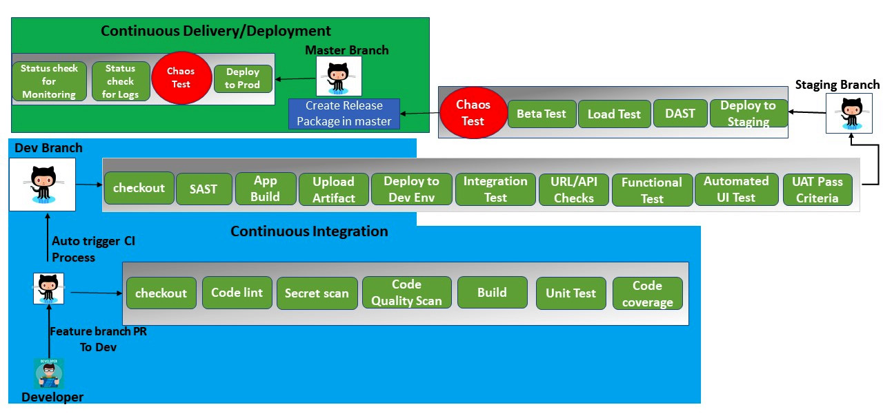
Figure 6.1 – Chaos test in CI/CD
In the preceding diagram, we are performing a chaos test after the application has been deployed in staging and is ready to be promoted to production. Before it is deployed to production, we need to monitor the behavior of the software system using a chaos test. Following that, we will implement a chaos test when the application is running in production. This test needs to be scheduled to run. During the test, we need to continuously monitor the system, too. We will actually implement a chaos test in CI/CD in Chapter 8, DevSecOps Using AWS Native Services and Chapter 9, DevSecOps Pipeline with AWS Services and Tools Popular Industry-Wide. In this chapter, we will run the FIS experiment template to first understand how chaos takes place in AWS workloads.
Experimenting with AWS FIS on multiple EC2 instances with a terminate action
In this section of the chapter, we will first deploy a sample application on EC2 instances, which will be part of the Autoscaling group. There will be a load balancer on top of the EC2 instance to handle the traffic. We will use FIS to terminate the EC2 instance and validate that the application is still accessible and that new EC2 instances are spinning up automatically and will serve the request shortly.
Perform the following steps to implement the experiment using AWS FIS:
- Create an IAM role, AmazonSSMRoleForInstanceQuickSetup, and attach the AmazonSSMManagedInstanceCore AWS managed policy. Then, go to the AWS EC2 console and click on Launch configurations in the bottom-left corner. Then, click on Create launch configuration.
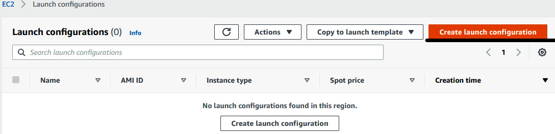
Figure 6.2 – Creating a launch configuration
- Provide the configuration information to create a launch configuration, as follows:
- Name: FIS-ASLC
- AMI: ami-01cc34ab2709337aa <Select AMI ID of Amazon Linux 2> based on your region
- Instance type: t2.micro
- IAM Instance profile: AmazonSSMRoleForInstanceQuickSetup
- In the Additional configuration section, under Advanced details, User data, paste the following snippet, which is a Bootstrap script that installs the Docker binary and runs a sample application. This application shows the IP address of the server on the web page:
#!/bin/bash
sudo yum update -y
sudo yum install docker -y
sudo systemctl start docker
sudo systemctl enable docker
sudo usermod -aG docker $USER
host=$(hostname)
sudo docker run -h $host --name $host -d -p 80:80 nicksrj/nova
- In Security groups, restrict SSH Source type to Custom IP and give your office/home IP address (you can get this from https://www.whatismyip.com) under Source, for example: 23.23.23.23/32.
- Click on Add new rule and add an HTTP port to anywhere.
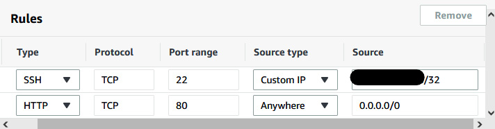
Figure 6.3 – Adding rules in security groups
- In Key pair (login), you can choose to select the existing key pair (make sure you have access to that key) or create a new key pair and click on Download key pair. Then, click on Create launch configuration.
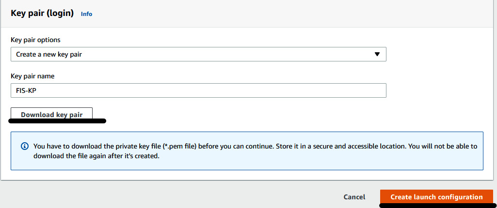
Figure 6.4 – Creating a new key pair
- You will have created your launch configuration.
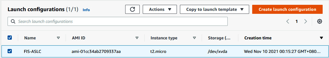
Figure 6.5 – Launch configurations list
- Click on Auto Scaling Groups in the bottom-left corner and then click on Create Auto Scaling group.
- Provide FIS-ASG in the Auto Scaling group name field. Then, click on Switch to launch configuration (if you are seeing the Launch template section). Select Launch Configuration FIS-ASLC, which we just created. Then, click on Next to proceed.
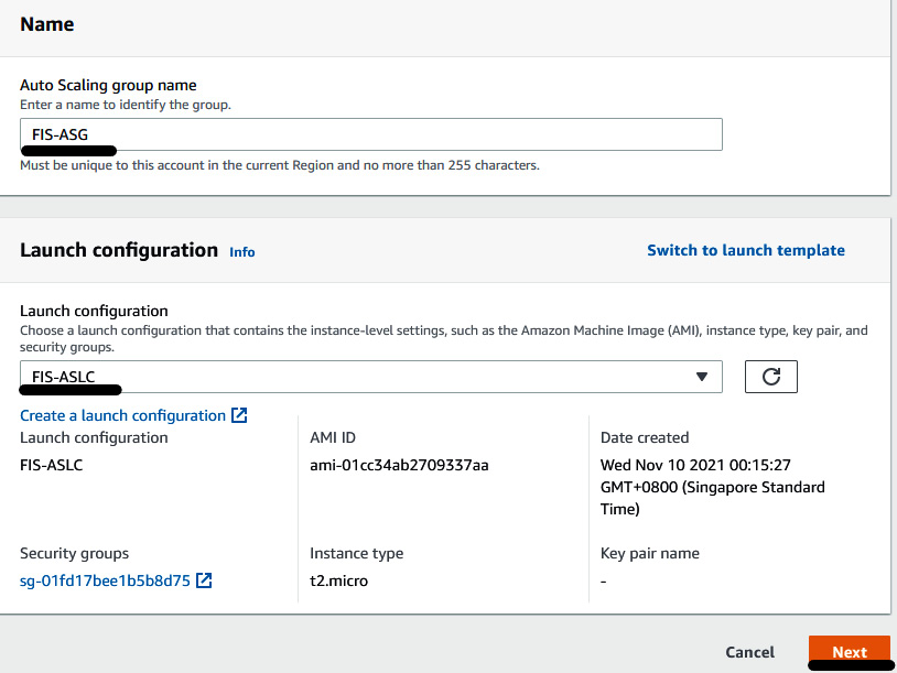
Figure 6.6 – Providing ASG information
- In the Network section, select the default VPC and two/three subnets. Then, click on Next:
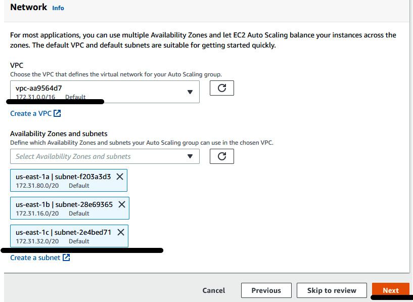
Figure 6.7 – Providing ASG network information
- In Load balancing, select Attach to a new load balancer. Make sure that Application Load Balancer has been selected as the load balancer type. Name the load balancer FIS-ALB. Under Load balancer scheme, select Internet-facing. In Listeners and routing, click on the Default routing dropdown and select Create a target group. Then, in the New target group field, provide a name of FIS-ALB-TG.
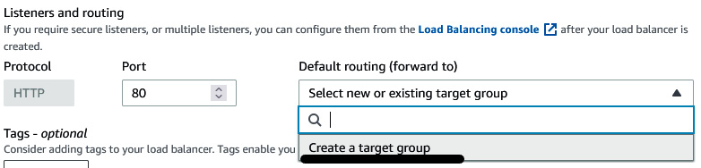
Figure 6.8 – Creating a load balancer and target group
- In Health checks, select ELB. Then, click on Next.
- In Group size, insert 2 under Desired capacity, 2 under Min, and 3 under Max.
- In Scaling policies, select Target tracking scaling policy. Then, select Disable scale in to create a scale-out policy only. Click on Next to proceed.
- You can add an SNS notification, but we are skipping this step in this exercise. Click on Next.
- Provide the tag details, which will be applied to EC2 instances spun up by this Auto Scaling Group (ASG). Insert Name in the Key field and FIS-Instance in the Value field. Then, click on Next to proceed to the review page.
- Once you have reviewed all the information, click on Create Auto Scaling group. After a few minutes, you will have created an ASG with two instances.

Figure 6.9 – ASG list
- You can verify the EC2 instance from the EC2 console and Application Load Balancer (ALB) from the Load Balancers console.
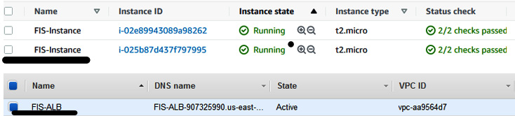
Figure 6.10 – The top image shows EC2 instances and the bottom image shows the load balancer
- Now, fetch the ALB DNS name, enter it in your browser, and you will be able to see the Nova application, which shows you the page getting served from which EC2 instance via the server name value. If you click on Auto Refresh, you will see that the Server name value will also change, meaning that the load balancer is transferring the request to both EC2 instances (172-31-44-121, 172-31-27-17).
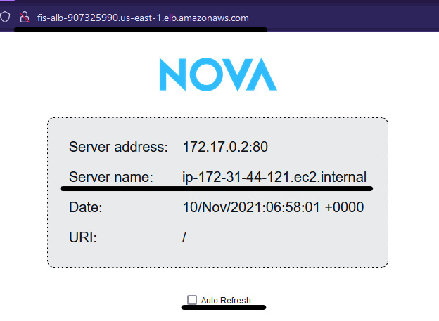
Figure 6.11 – Nova web application
- Once you have an app running, we need to create chaos by terminating an EC2 instance and verifying whether the application is still live and the new EC2 instance spins up and starts serving after a few minutes. You need to create an IAM role that will allow FIS to perform an action on the resources, including EC2 or RDS. Create a policy, fis-ec2-policy, with the following JSON snippet:
{
"Version": "2012-10-17",
"Statement": [
{
"Sid": "AllowFISExperimentRoleEC2ReadOnly",
"Effect": "Allow",
"Action": [
"ec2:DescribeInstances"
],
"Resource": "*"
},
{
"Sid": "AllowFISExperimentRoleEC2Actions",
"Effect": "Allow",
"Action": [
"ec2:RebootInstances",
"ec2:StopInstances",
"ec2:StartInstances",
"ec2:TerminateInstances"
],
"Resource": "arn:aws:ec2:*:*:instance/*"
},
{
"Sid": "AllowFISExperimentRoleSpotInstanceActions",
"Effect": "Allow",
"Action": [
"ec2:SendSpotInstanceInterruptions"
],
"Resource": "arn:aws:ec2:*:*:instance/*"
}
]
}
- Create an IAM role, FIS-EC2-Role, and attach the fis-ec2-policy policy. Then, replace the trust relationship of the role with the following snippet:
{
"Version": "2012-10-17",
"Statement": [
{
"Effect": "Allow",
"Principal": {
"Service": [
"fis.amazonaws.com"
]
},
"Action": "sts:AssumeRole"
}
]
}
- Go to the AWS FIS console and click on Create experiment template.
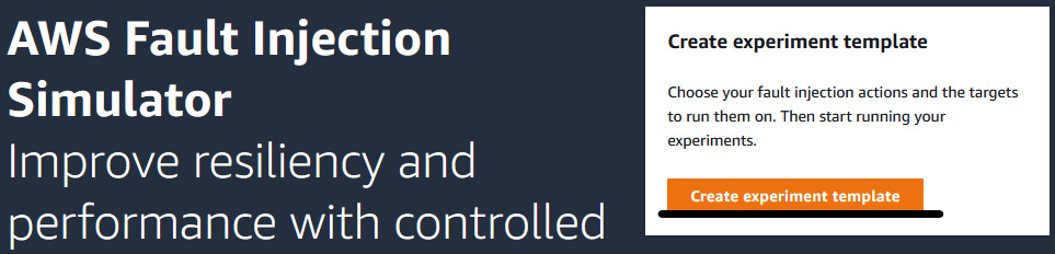
Figure 6.12 – FIS console page
- On the Create experiment template page, under Description, provide the information related to the experiment (Experiment on ASG EC2 instance with Terminate action). Name the template EC2-Terminate-Experiment. In the IAM role field, select FIS-EC2-Role from the dropdown.
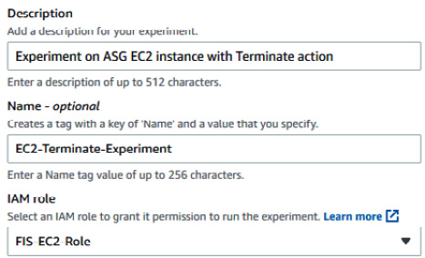
Figure 6.13 – Experiment template information
- In Action section, insert EC2-Teminate in both the Name and Description fields. Under Action type, select aws:ec2:terminate-instances, select and Instances-Target-1 in the Target field. This is a default target name. Later, when you change the name of the target, you need to modify it here as well. Click on Save to save the action.
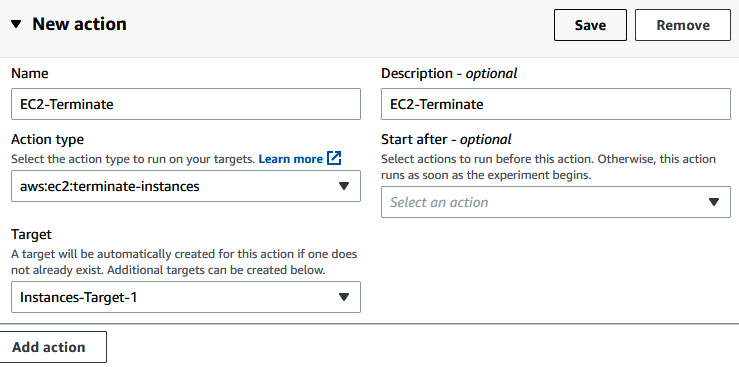
Figure 6.14 – Providing FIS Action details
- Expand the Instances-Target-1 (aws:ec2:instance) field and click on Edit. Under Target method, select Resource tags and filters. Under Selection mode, choose Percent, and provide a value of 50. Under Resource tags, insert Name in the Key field and FIS-Instance in the Value field. Then, click on Add new filter, insert State.Name in the Attribute path field, and running in the Values field. Then, click on Save.
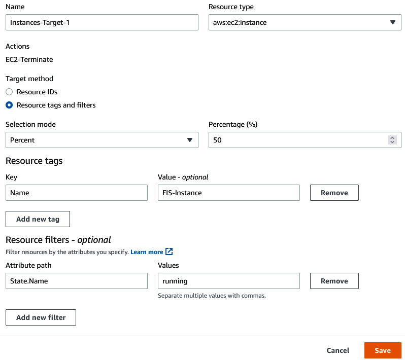
Figure 6.15 – Providing FIS target details
- Click on Create experiment template to create the FIS experiment template. For now, we are not creating a stop condition for the experiment, so enter the permissible string.
- At this stage, the two instances we have are 172.31.27.17 and 172.31.44.121, which can be validated from the Nova web page. Now, go to the experiment template Actions dropdown and click on Start.
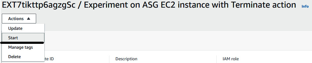
Figure 6.16 – Starting the FIS experiment template
- Insert Name in the Key field and EC2-Term-Exp-1 in the Value field and then click on Start experiment. It will ask for confirmation again because we are going to perform an experiment that will terminate your resource. Provide the confirmation string and then click on Start experiment.
- Once you start the experiment, it will be in a pending and running state because it will invoke EC2 terminate action on the 50% of instances tagged with IFS-Instance.
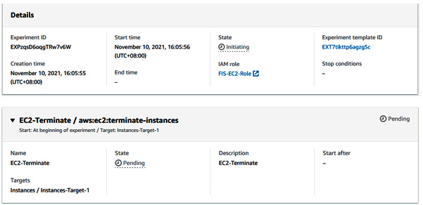
Figure 6.17 – FIS experiment status and details
- Once the experiment starts, you can navigate to the EC2 console, and you will see that one of the EC2 instances is in the Terminated state.

Figure 6.18 – Instance in a terminated state
- Even in the Nova web application, the request is served from 172.31.27.17, and not from 172.31.44.121, because it has been terminated.
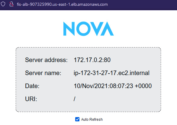
Figure 6.19 – Nova web application served by the 172.31.27.17 server only
- At the same time, ASG will create another EC2 instance because our desired number of instances was two, and right now only one is in a running state. So, you can verify that the new instance is also spinning up.

Figure 6.20 – New instance in a running state
- At the same time, you can go to the Target group console and see that the new instance is being registered in the load balancer.
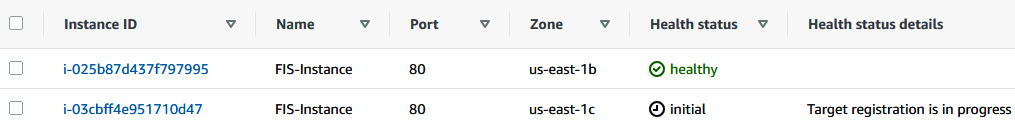
Figure 6.21 – A new instance being registered in the Target group
- After a few minutes, once the server is registered, you can see in the Nova web app that the request is now getting served from the new instance too (172.31.34.232).
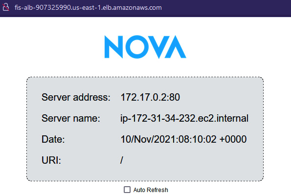
Figure 6.22 – Nova web application served by a new instance
- If you go to the experiment page again, you can see the state of the experiment is Completed.
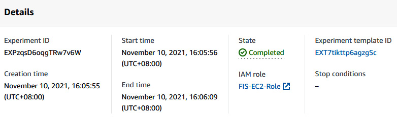
Figure 6.23 – FIS experiment completed
So, we just saw how AWS FIS created chaos in our existing running infrastructure, and since our application was running on an EC2 instance, which was backed by ASG and a load balancer, it recovered itself within a few minutes. In the next section, we will perform another experiment that is related to CPU stress on an EC2 instance.
Experimenting with AWS FIS on EC2 instances with a CPU stress action
In this section of the chapter, we will create an FIS experiment template that applies CPU stress to an EC2 instance using Amazon Systems Manager Agent. We will validate the fact that once the chaos experiment starts giving CPU stress to an EC2 instance and CPU utilization of the server increases by more than 50%, then ASG should automatically increase a new instance and take over the load.
Perform the following steps to implement the experiment using AWS FIS:
- Since the AWS FIS CPU stress action uses an SSM agent on an EC2 instance, make sure that the SSM agent is installed and that the AmazonSSMRoleForInstanceQuickSetup IAM role is attached to both servers running in ASG. Amazon Linux 2 AMI comes with an SSM agent installed and in a running state. In Step 2 | IV of the previous section, Experimenting with AWS FIS on multiple EC2 instances with a terminate action, we also applied the IAM role to the launch configuration.
- If you are using SSM for the first time, then you need to go to the AWS Systems Manager console, click on Quick Setup in the top-left corner, click on the required region, and then click on Get Started.
Figure 6.24 – AWS Systems Manager console
- Click on Create new configuration, and then click on Host Management. Click on Next to proceed to the next page and then click on Create to complete the setup.
- You will see that Configuration deployment status is in the Running state.

Figure 6.25 – Host management configuration deployment status
- After some time, you will see that the host management configuration deployment is successful.
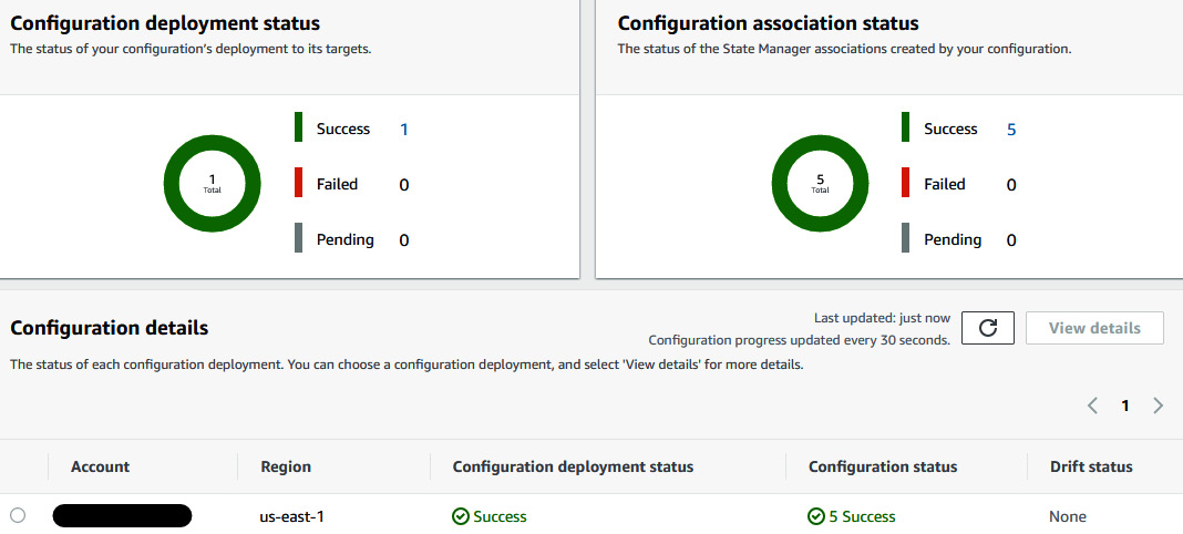
Figure 6.26 – Success status of the configuration deployment
- Now you need to create an IAM policy, fis-ssm-policy, using the following snippet:
{
"Version": "2012-10-17",
"Statement": [
{
"Sid": "AllowFISExperimentRoleSSMReadOnly",
"Effect": "Allow",
"Action": [
"ec2:DescribeInstances",
"ssm:GetAutomationExecution",
"ssm:ListCommands"
],
"Resource": "*"
},
{
"Sid": "AllowFISExperimentRoleSSMSendCommand",
"Effect": "Allow",
"Action": [
"ssm:SendCommand"
],
"Resource": [
"arn:aws:ec2:*:*:instance/*",
"arn:aws:ssm:*:*:document/*"
]
},
{
"Sid": "AllowFISExperimentRoleSSMCancelCommand",
"Effect": "Allow",
"Action": [
"ssm:CancelCommand"
],
"Resource": "*"
},
{
"Sid": "AllowFISExperimentRoleSSMAutomation",
"Effect": "Allow",
"Action": [
"ssm:StartAutomationExecution",
"ssm:StopAutomationExecution"
],
"Resource": "*"
},
{
"Sid": "AllowFISExperimentRoleSSMAutomationPassRole",
"Effect": "Allow",
"Action": [
"iam:PassRole"
],
"Resource": "arn:aws:iam::<Your_Account_ID>:role/ AmazonSSMRoleForInstanceQuickSetup"
}
]
}
- Create an IAM role, FIS-SSM-Role, and attach the fis-ssm-policy policy. Also, edit the trust relationship of the role with the following JSON snippet:
{
"Version": "2012-10-17",
"Statement": [
{
"Effect": "Allow",
"Principal": {
"Service": "fis.amazonaws.com"
},
"Action": "sts:AssumeRole"
}
]
}
- Now, go to the FIS console and click on Create experiment template.
- Provide the following details in the Description, Name, and IAM Role fields:
- Description: Experiment on ASG EC2 instance with CPU stress action
- Name: EC2-CPU-Stress-Experiment
- IAM Role: FIS-SSM-Role
- Provide the following information in the Action section:
- Name: CPU-Stress-Action.
- Description: CPU-Stress-Action.
- Action type: aws:ssm:send-command/AWSFIS-Run-CPU-Stress.
- documentParameters: {"DurationSeconds":"400"}.
- Duration: 6 Minute
- Click on Save.
- Edit the Targets field. Under Target method, select Resource tags and filters. In Selection mode, select All. Under Resource tags, click on Add new tag. Insert Name in the Key field and FIS-Instance in the Value field. Under Resource filters, click on Add new filter. Insert State.Name in the Attribute path field and running in the Values field. Then, click on Save.
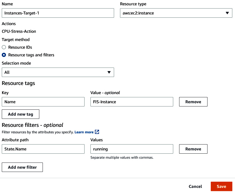
Figure 6.27 – Providing FIS target details
- Click on Create experiment template. Provide a confirmation string and then click on Create experiment template.
- Once you have created the template, we can start the experiment. Click in the Actions dropdown and then select Start. Provide the tag. Click on Start experiment. It will ask for confirmation again because we are going to perform an experiment that will impact your resource. Provide the confirmation string and click on Start experiment.
- Once you start the experiment, the experiment will be in the Running status.
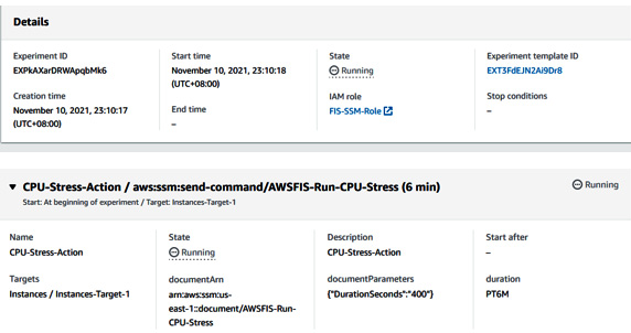
Figure 6.28 – Status of the FIS experiment
- Go to the EC2 console, monitor one of the EC2 instances, and you will see that the CPU utilization of the server will go to more than 50%.
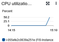
Figure 6.29 – CPU utilization of an instance
- The moment it reaches 50% CPU utilization, the ASG scaling policy (which we set in step 10 of the previous section, Experimenting with AWS FIS on multiple EC2 instances with a terminate action) will trigger, which scales the EC2 server from two to three instances.
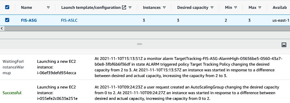
Figure 6.30 – Message upon reaching the CPU threshold and spinning a new instance
- You can verify the new third EC2 instance in the EC2 console.
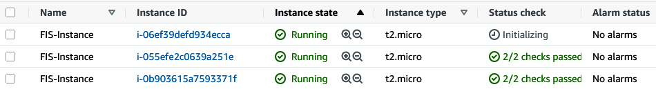
Figure 6.31 – New instance coming up
- You can also verify that the Nova web application is also served from the new EC2 instance (172.31.38.94).
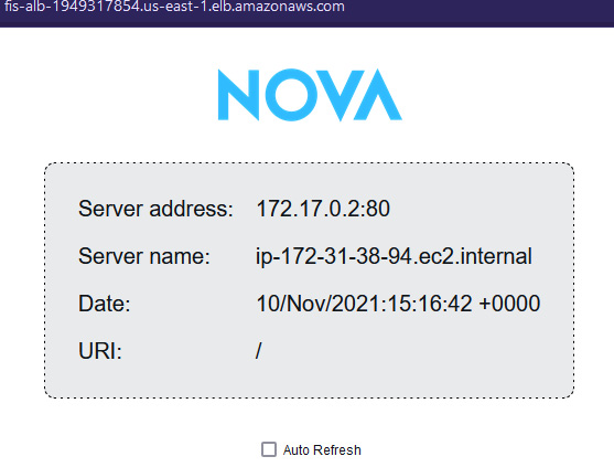
Figure 6.32 – Nova web application served from the new instance
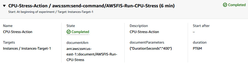
Figure 6.33 – Status of the FIS experiment
So, we just saw how AWS FIS created chaos on our existing running infrastructure, and since our application was running on an EC2 instance, which was backed by ASG with a scaling policy, it spins up another EC2 instance. In the next section, we will perform an action related to RDS master to RDS reader failover step.
Experimenting with AWS FIS on RDS with a reboot and failover action
In this section of the chapter, we will create an FIS experiment template that will invoke an API call to reboot a database cluster with failover. In failover, the read-only replica will be promoted as the primary instance (the cluster writer), and you can also see that the availability zone in use will also change. We will validate by reviewing the availability of the application during the reboot and failover of MySQL RDS. We will deploy an example Node.js REST API application with MySQL RDS.
Perform the following steps to implement the experiment using AWS FIS:
- Go to the RDS console and click on Create database.
- Select Standard create under Choose a database creation method. Select MySQL under Engine type.
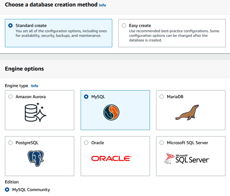
Figure 6.34 – Choosing a database engine
- Under Templates, select Dev/Test, while under DB instance identifier, enter RDS-FIS. Complete the Master password and Confirm password fields.
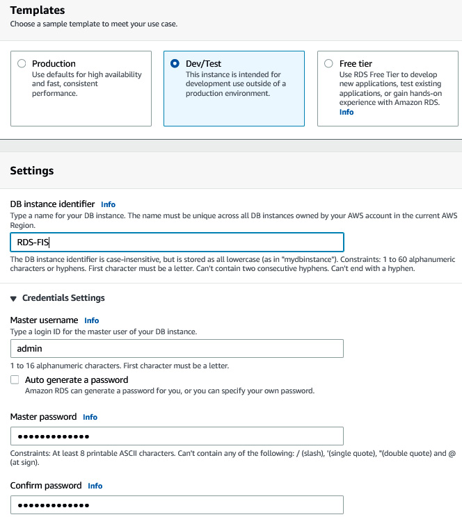
Figure 6.35 – Providing database credentials
- Under DB instance class, select Burstable classes and Include previous generation classes (to enable older and cheaper instance types since this is an experiment). Deselect Enable storage autoscaling.
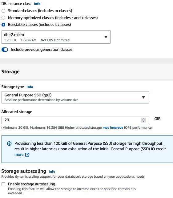
Figure 6.36 – Providing database storage details
- Under Multi-AZ deployment, select Create a standby instance. Under Virtual private cloud (VPC), select Default VPC. Select Yes under Public access (not recommended in production). Choose the default security group.
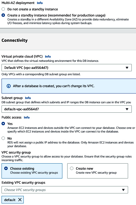
Figure 6.37 – Providing database network details
- Select Password authentication under the database authentication options. Expand Additional configuration and then, in the Initial database field, insert student_dev and then click on Create database. You will see that a database instance will be in the Creating state. After 10-15 minutes, the database status will change to Available. Once you click on the database and select the Configuration tab, you will see the necessary information, which shows that the database is Multi-AZ, that the primary AZ is us-east-1b (in my case), while the secondary AZ is us-east-1f.
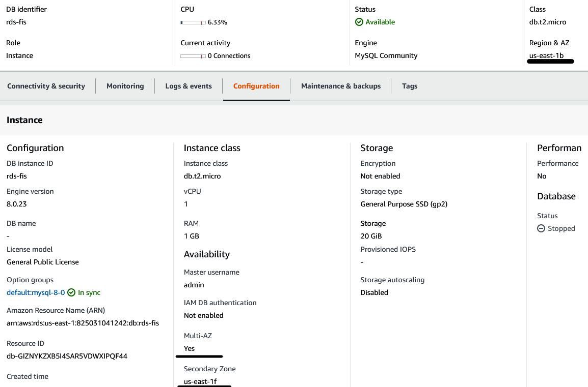
Figure 6.38 – RDS configuration information
- Go to Security group rule ID (which is the default security group) and add a MYSQL/Aurora rule for the VPC CIDR (in my case, 172.31.0.0/16) source because we will spin up an EC2 instance, which runs an application, in the same VPC.
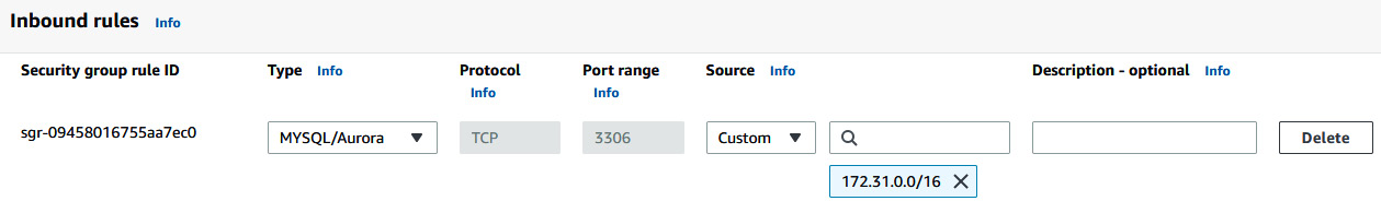
Figure 6.39 – Adding a MySQL rule to the RDS Security group
- Now you need to spin up an EC2 instance with Amazon Linux 2 AMI and select the default VPC, enable the subnet, provide the following user data script (change the password and database endpoint in the script), provide 10 GB of storage, enable SSH and HTTP (to your home/office IP address), and select a key pair that you already have:
#!/bin/bash
sudo yum update -y
sudo yum install docker mysql telnet git jq -y
sudo systemctl enable docker
sudo systemctl start docker
sudo amazon-linux-extras install epel -y
sudo yum install moreutils -y
git clone https://github.com/PacktPublishing/Modern-CI-CD-on-AWS.git
cd Modern-CI-CD-on-AWS/chapter-06-nodejsrestapi
jq '.development.username = "admin"' config/config.json | sponge config/config.json
jq '.development.password = "<DB_PASSWORD>"' config/config.json | sponge config/config.json
jq '.development.host = "<DB_ENDPOINT>"' config/config.json | sponge config/config.json
sudo docker build -t nodejs-express-mysql:v1 .
sudo docker run -d -p 80:3000 -p 3306:3306 --name nodejs-api-app nodejs-express-mysql:v1
- Once you have your EC2 instance ready, fetch the public IP address of the server and put it in Postman (you can download Postman here: https://www.postman.com/downloads/). In my case, the public IP address is 54.91.118.188. You perform a GET request and insert the URL as http://PUBLIC_IP/students. You will get an empty array, [], as a reply, which means that database connectivity is there, just that there is no data.
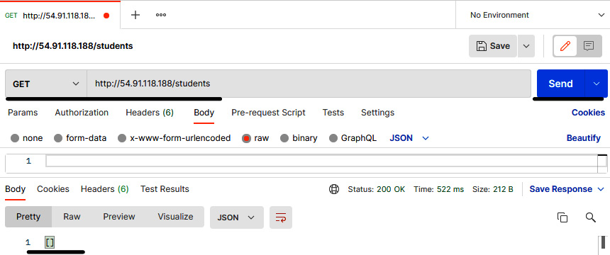
Figure 6.40 – Postman console showing the GET request result of the student record
- We will upload a student record that will be saved in the database. Use a POST request with the following body. You will see the message Post created successfully:
{
id: 1,
firstname": "Julius",
lastname": "Caesar",
class: 3A,
nationality: Rome
}
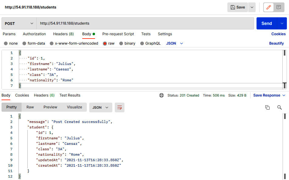
Figure 6.41 – Postman Console showing the POST request result of the student record
- Now you can run the same GET request as you did in step 9, and you will get the student record. This means that our application is running fine and able to add and read data from the database.
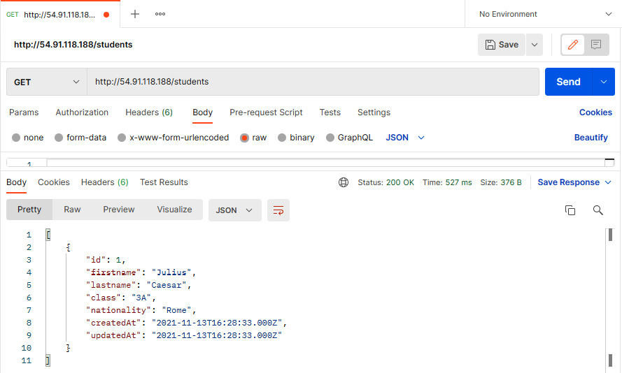
Figure 6.42 – Postman console showing the GET request result of the student record
- Now we will create an FIS experiment template to inject a database reboot and failover, which will have an impact on the application. Before we create an experiment template, we need to create an IAM policy, fis-rds-policy, using the following code snippet:
{
"Version": "2012-10-17",
"Statement": [
{
"Sid": "AllowFISExperimentRoleRDSReadOnly",
"Effect": "Allow",
"Action": [
"rds:DescribeDBInstances",
"rds:DescribeDbClusters"
],
"Resource": "*"
},
{
"Sid": "AllowFISExperimentRoleRDSReboot",
"Effect": "Allow",
"Action": [
"rds:RebootDBInstance"
],
"Resource": "arn:aws:rds:*:*:db:*"
},
{
"Sid": "AllowFISExperimentRoleRDSFailOver",
"Effect": "Allow",
"Action": [
"rds:FailoverDBCluster"
],
"Resource": "arn:aws:rds:*:*:cluster:*"
}
]
}
- Create an IAM role, FIS-RDS-Role, and attach fis-rds-policy to it. Edit the trust relationship with the following snippet:
{
"Version": "2012-10-17",
"Statement": [
{
"Effect": "Allow",
"Principal": {
"Service": [
"fis.amazonaws.com"
]
},
"Action": "sts:AssumeRole"
}
]
}
- Once the IAM role has been created, go to the FIS console and click on Create experiment template. Provide the following details in the Description, Name, and IAM Role fields:
- Description: RDS-Resiliency-Test
- Name: RDS-Resiliency-Test
- IAM Role: FIS-RDS-Role
- Provide the following information in the Action section. Then, click on Save:
- Name: RDS-FIS-Action
- Action type: aws:rds:reboot-db-instances
- Target: DBInstance-Target-1
- forceFailover: true
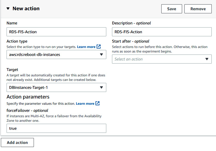
Figure 6.43 – Providing details for the FIS action
- Click on Edit in DBInstances-Target-1. Click on the Resource IDs dropdown and select the rds-fis RDS instance, and then click on Save. Then, click on Create experiment template.
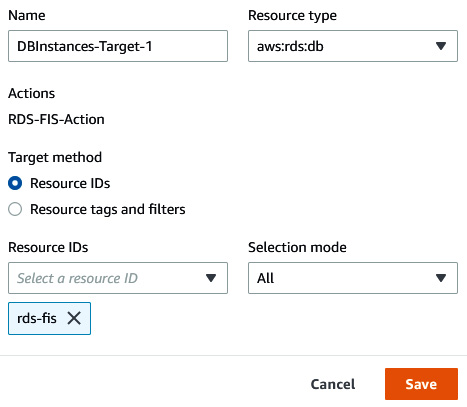
Figure 6.44 – Providing FIS target details
- Once you have created an experiment template, click on the Action dropdown button and then click on Start to start the experiment. Provide a tag and give a confirmation string because you are going to perform disruptive action on your application environment.
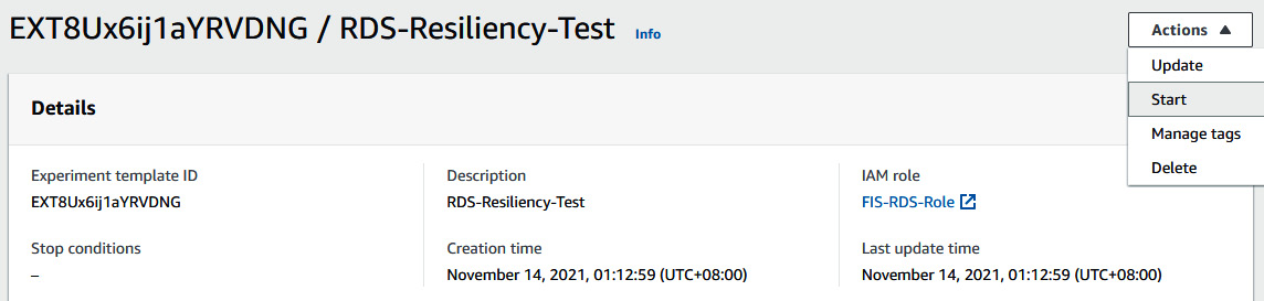
Figure 6.45 – Starting the FIS experiment
- Once you have started the experiment, you can see that the state of the action will be Running.
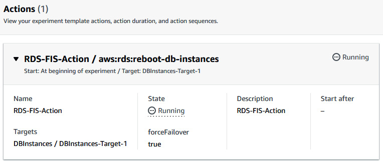
Figure 6.46 – Status of the FIS experiment template
- After that, keep on sending GET requests in Postman to receive the student record. At a certain point, for a few seconds, you will see a 500 error message with something went wrong, which means that the database is rebooting (you can verify this from the RDS console) and failing over to another availability zone.
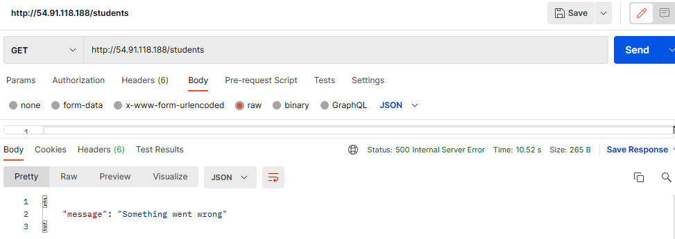
Figure 6.47 – Postman console showing an error message with the GET request
- The GET request will show the error message only for a few seconds, and once you resend the request, you will see the student record.
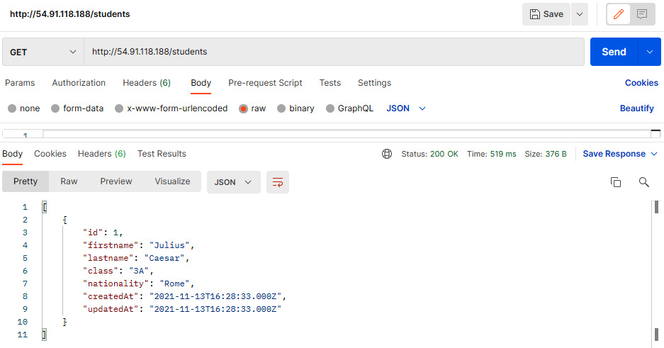
Figure 6.48 – Postman console showing the GET request result of the student record
- Since you are getting the student record, you can go to the RDS console and check the status of the database as well as the current availability. The status of the database will be Available, while the availability zone will be switched from us-east-1b to us-east-1f.
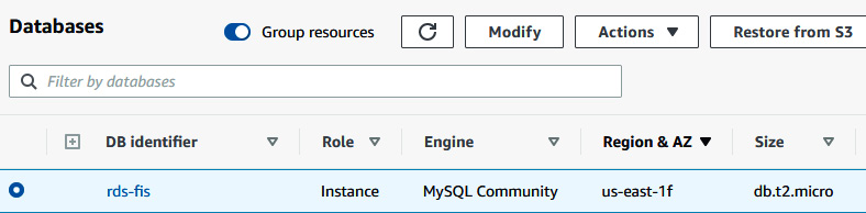
Figure 6.49 – RDS console
- After that you can go to the FIS console to see the status of RDS-FIS-Action. It will now be Completed.
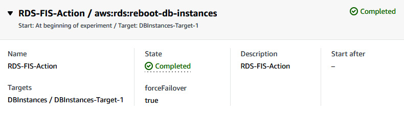
Figure 6.50 – FIS experiment status
So, we just did an experiment where AWS FIS is creating chaos on the Node.js application by rebooting and failing over the RDS. Since RDS is a managed service and has the capability of rebooting and automatic failover within a minute, the application downtime is less than a minute. In the next section, we will try to inject node group failure into an EKS cluster.
Experimenting with AWS FIS on an EKS cluster worker node
In this section of the chapter, we will use FIS to create a disturbance on an EKS cluster by terminating instances of worker node groups. We will deploy an application on an EKS cluster and then we will start the FIS experiment to delete instances of worker nodes and see whether the application is running fine.
Perform the following steps to implement the experiment using AWS FIS:
- Spin up an EKS cluster by running the following command on your terminal (make sure your server or local machine has aws cli configured with the user who has permission to access the EKS).
$ ssh-keygen -y -f <$PRIVATE_KEY_FILE_PATH> public.pem
$ eksctl create cluster --name fis-cluster --region us-east-1 --ssh-access --ssh-public-key public.pem
- Check the number of worker nodes in the cluster. It should be two:
### Make sure .kube/config file is present.
$kubectl get nodes
NAME STATUS ROLES AGE VERSION
ip-192-168-26-157.ec2.internal Ready <none> 3h54m v1.21.5-eks-bc4871b
ip-192-168-50-4.ec2.internal Ready <none> 5h12m v1.21.5-eks-bc4871b
- You can go to the EKS console and see the node group of fis-cluster. The node group name in this case is ng-69f2e42f and it contains two worker nodes:
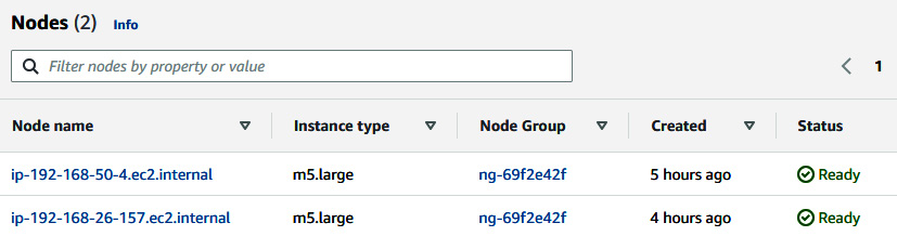
Figure 6.51 – EKS worker nodes
- Now, deploy an application on an EKS cluster, which will spread across worker node instances:
$ curl -o kube-app.yaml https://raw.githubusercontent.com/PacktPublishing/Accelerating-DevSecOps-on-AWS/main/chapter-06-starkapp/kube-deployment.yml
$ kubectl create -f kube-app.yaml
- Once you try to get the Pod information, you will see that Pod placement is spread in both instances (192.168.26.157 and 192.168.50.4):
$ kubectl get pods -o wide
NAME READY STATUS RESTARTS AGE IP NODE NOMINATED NODE READINESS GATES
db-79468d5ff4-zqwhk 1/1 Running 0 21s 192.168.16.205 ip-192-168-26-157.ec2.internal <none> <none>
web-67c6fbbfb5-hpn96 1/1 Running 0 18s 192.168.4.170 ip-192-168-26-157.ec2.internal <none> <none>
words-59dc77b9db-bhrtg 1/1 Running 0 19s 192.168.59.102 ip-192-168-50-4.ec2.internal <none> <none>
words-59dc77b9db-d454t 1/1 Running 0 19s 192.168.25.241 ip-192-168-26-157.ec2.internal <none> <none>
words-59dc77b9db-qjqw6 1/1 Running 0 19s 192.168.8.77 ip-192-168-26-157.ec2.internal <none> <none>
words-59dc77b9db-t5chq 1/1 Running 0 19s 192.168.1.90 ip-192-168-26-157.ec2.internal <none> <none>
words-59dc77b9db-w9q98 1/1 Running 0 19s 192.168.36.9 ip-192-168-50-4.ec2.internal <none> <none>
- You can get the DNS endpoint of a web service that is exposed as a load balancer:
kubectl get svc | grep web
web LoadBalancer 10.100.106.64 a3c0ee988db4546e7b5c9ffd86de36a2-1187254052.us-east-1.elb.amazonaws.com 80:31738/TCP 3m20s
- Copy the ELB DNS and access it in the browser. You will see a Stark word application (every time you refresh the page, you will see a different word box).
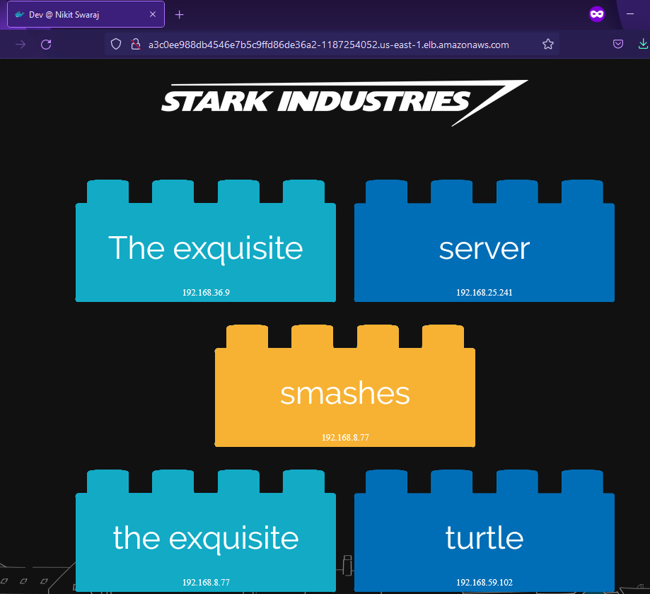
Figure 6.52 – stark-word-app
- Since your application is running fine on an EKS cluster and spread across multiple worker nodes, let's create chaos using an FIS EKS terminate node group instance action to test the resiliency of the infrastructure. Go to IAM and create an IAM policy, fis-eks-policy, using the following code snippet:
{
"Version": "2012-10-17",
"Statement": [
{
"Sid": "AllowFISExperimentRoleEKSReadOnly",
"Effect": "Allow",
"Action": [
"ec2:DescribeInstances",
"eks:DescribeNodegroup"
],
"Resource": "*"
},
{
"Sid": "AllowFISExperimentRoleEKSActions",
"Effect": "Allow",
"Action": [
"ec2:TerminateInstances"
],
"Resource": "arn:aws:ec2:*:*:instance/*"
}
]
}
- Create an IAM role, FIS-EKS-Role, and attach the fis-eks-policy policy. Edit the trust relationship of the role using the following code snippet:
{
"Version": "2012-10-17",
"Statement": [
{
"Effect": "Allow",
"Principal": {
"Service": [
"fis.amazonaws.com"
]
},
"Action": "sts:AssumeRole"
}
]
}
- Once an IAM role is created, go to the FIS console, and click on Create experiment template. Provide the following details in the Description, Name, and IAM Role fields:
- Description: EKS-Node-Resiliency-Test
- Name: EKS-Node-Resiliency-Test
- IAM Role: FIS-EKS-Role
- Provide the following information in the Action section:
- Name: EKS-Node-Termination-Action.
- Action type: aws:eks:terminate-nodegroup-instances.
- Target: Nodegroups-Target-1.
- instanceTerminationPercentage: 50.
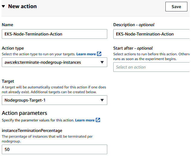
Figure 6.53 – Providing FIS action details
- Click on Save to save the action.
- Click on Edit in Nodegroups-Target-1. Select the node group name of the FIS cluster (in this case, ng-69f2e42f). Under Selection Mode, select Count, and then, in the Number of resources field, insert 1. Click on Save to save the target. Then, click on Create experiment template. Provide a confirmation string and then click on Create experiment template.
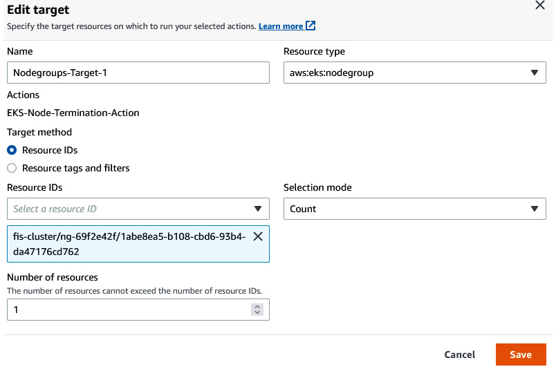
Figure 6.54 – Providing FIS target details
- Once you have created an experiment template, click on Actions followed by Start experiment to start the experiment. Provide the tag and confirmation string.
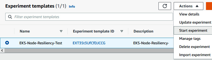
Figure 6.55 – Starting the FIS experiment
- You will see that the experiment will be initiated and in the Running state.
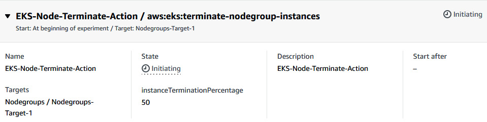
Figure 6.56 – Status of the FIS experiment
- When the experiment starts, it invokes an API call to terminate 50% of the node group (one instance). You can go to the EC2 console to see that one of the worker nodes has been terminated (192.168.50.4).
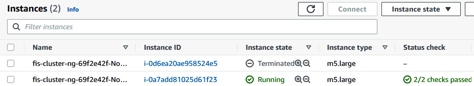
Figure 6.57 – EC2 console showing one worker node terminated
- When one of the worker nodes terminates, any Pods in the terminated worker node will move to the running worker node (192.168.26.157).
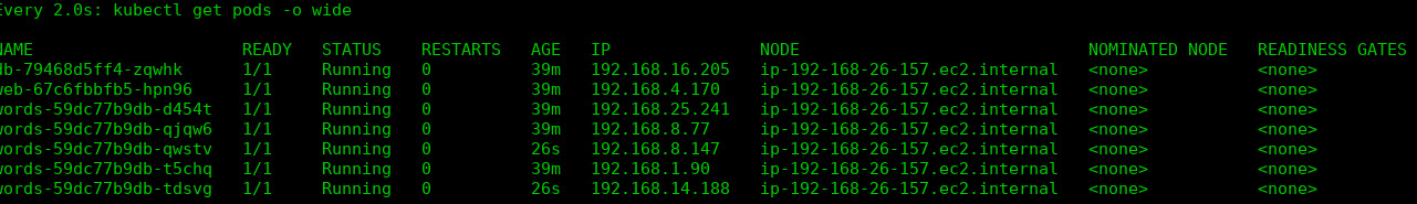
Figure 6.58 – Showing all the Pods placed on one worker node; ip-192-168-26-157
- When you try to access the application, it will still be available.
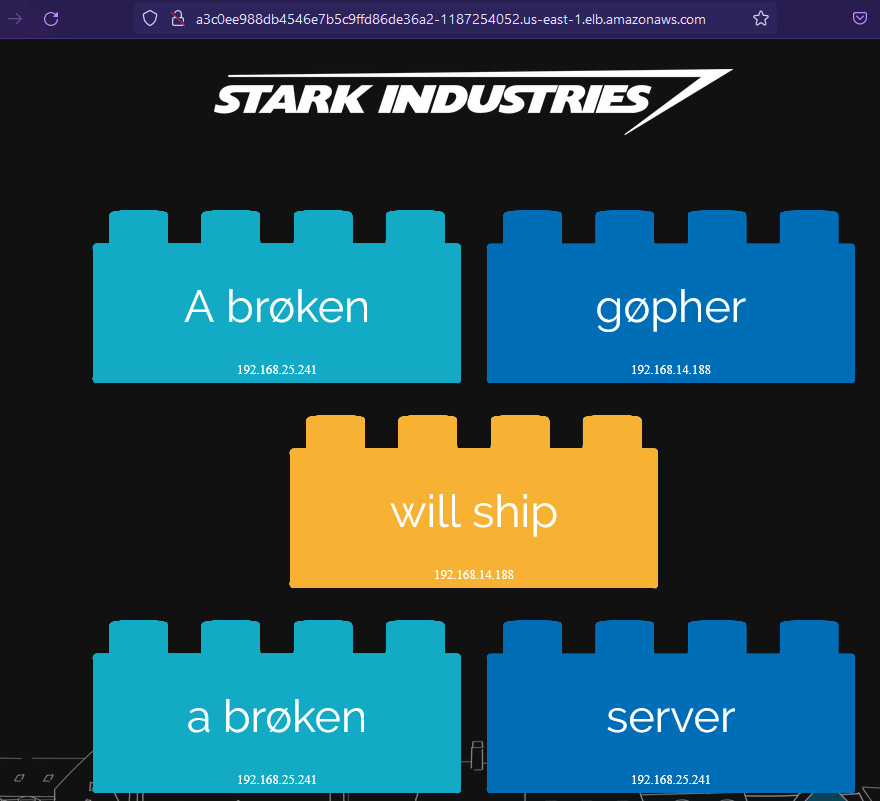
Figure 6.59 – stark-word-app
- Since the node group is backed by ASG and the desired number of worker nodes is two, ASG will spin up another instance to meet the desired number of instances.
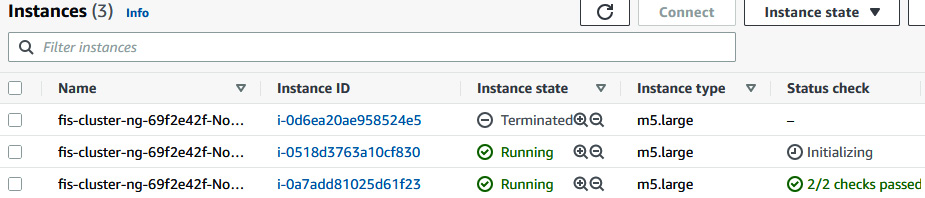
Figure 6.60 – EC2 console showing a new EC2 instance spinning up
- After a while, when you run the following command, you will see that the new worker node is available in the EKS cluster.
$ kubectl get nodes
NAME STATUS ROLES AGE VERSION
ip-192-168-26-157.ec2.internal Ready <none> 4h47m v1.21.5-eks-bc4871b
ip-192-168-57-215.ec2.internal Ready <none> 54s v1.21.5-eks-bc4871b
- When you go back to the FIS experiment state, it will be in the Completed state.

Figure 6.61 – FIS experiment status
We just performed an experiment where we created a disturbance on stark-word-application using the AWS FIS EKS node group instance terminate action. We saw how EKS manages the application Pod by scheduling it to the available running worker node. And since the node group is backed by ASG, it spins up a new worker node to meet the desired number of instances.
Summary
Chaos engineering is one of the important steps in testing the resiliency of the infrastructure and applications running on top of it. In this chapter, we covered the principle of chaos engineering and how we can position it in the CI/CD framework to automate the chaos testing of infrastructure. We learned more about the managed chaos engineering service, Fault Injection Simulator. We performed various chaos actions on running application infrastructure and concluded the downtime. In the next chapter, we will learn how to automate the security posture in the cloud using AWS.