
4. Working with Objects
Lesson Overview
In this lesson, you’ll learn how to do the following:
• Work with layers.
• Create and edit text frames and graphics frames.
• Import graphics into graphics frames.
• Crop, move, and scale graphics.
• Adjust the space between frames.
• Add captions to graphics frames.
• Place and link graphics frames.
• Change the shape of frames.
• Wrap text around an object or graphic.
• Create complex frame shapes.
• Convert frame shapes to other shapes.
• Modify and align objects.
• Select and modify multiple objects.
• Create a QR code.
• Add arrowheads to a line.

This lesson will take approximately 90 minutes.
To download the project files for this lesson, log in or set up an account at peachpit.com. Enter the book’s ISBN (9780134664095) or go to the book’s product page to register. On the book’s page, click Register Your Product. The book shows up in your list of registered products along with a link to the book’s bonus content. Click the link to access the lesson files. Store the files on your computer in a convenient location. Your Account page is also where you’ll find any updates to the chapters or lesson files.

InDesign frames can contain text, graphics, or color. As you work with frames, you’ll discover that Adobe InDesign provides you with a great amount of flexibility and control over your design.
Getting started
In this lesson, you’ll work on a pair of spreads that make up a four-page newsletter. You’ll add text and images and make several modifications to the objects on the two spreads.
1 To ensure that the preferences and default settings of your Adobe InDesign program match those used in this lesson, move the InDesign Defaults file to a different folder following the procedure in “Saving and restoring the InDesign Defaults file” on pages 4–5.
2 Start Adobe InDesign. To ensure that the panels and menu commands match those used in this lesson, choose Window > Workspace > [Advanced], and then choose Window > Workspace > Reset Advanced. To begin working, you’ll open an InDesign document that is already partially completed.
![]() Note
Note
If an alert is displayed when you open the sample document, click Update Links.
3 Choose File > Open, and open the 04_Start.indd file in the Lesson04 folder, located inside the Lessons folder within the InDesignCIB folder on your hard drive. (If the Missing Fonts dialog box displays, click Sync Fonts, and then click Close after the fonts have successfully synced from Typekit.)
4 Choose File > Save As, rename the file 04_Objects.indd, and save it in the Lesson04 folder.
![]() Note
Note
As you work through the lesson, move panels or change the zoom level to a magnification that works best for you.
5 To see what the finished document looks like, open the 04_End.indd file in the same folder. You can leave this document open to act as a guide as you work. When you’re ready to resume working on the lesson document, choose Window > 04_Objects.indd or click its tab at the top of the document window.
![]() Tip
Tip
In the printing industry, facing pages in a multipage publication, as well as the front and back cover pages because they’re printed side-by-side, are commonly referred to as printer spreads.

The newsletter that you will work on in this lesson contains two spreads: The spread on the left contains page 4 (the back page on the left) and page 1 (the cover on the right); the spread on the right contains pages 2 and 3 (the center spread). Keep this page arrangement in mind as you navigate from page to page. Here you see the finished newsletter.
Working with layers
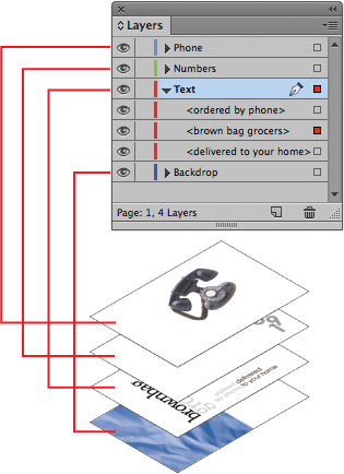
Before you begin creating and modifying objects, you should understand how layers work in InDesign. By default, every new InDesign document contains one layer (named Layer 1). You can rename this layer and add more layers at any time as you work on a document. Placing objects on different layers lets you organize them for easy selection and editing. In the Layers panel, you can select, display, edit, and print different layers individually, in groups, or all together.
The 04_Objects.indd document has two layers. You’ll experiment with these layers to learn how the arrangement of the layers and the placement of objects on layers can affect the design of your document, and you’ll add a new layer.
About layers

1 Click the Layers panel icon or choose Window > Layers to open the Layers panel.
2 If the Text layer is not selected in the Layers panel, click to select it. The layer is highlighted to indicate that it’s selected. Notice that a pen icon (![]() ) appears to the right of the layer name. The pen icon indicates that this layer is the target layer, and while it’s selected, anything you import or create is placed on this layer.
) appears to the right of the layer name. The pen icon indicates that this layer is the target layer, and while it’s selected, anything you import or create is placed on this layer.
3 Click the small triangle to the left of the Text layer name. All of the groups and objects on this layer are now displayed below the layer name. Use the panel’s scroll bar to view the names in the list, and then click the triangle again to hide them.
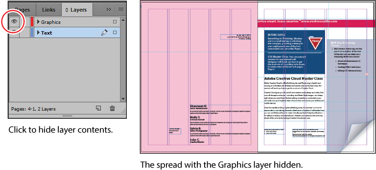
4 Click the eye icon (![]() ) to the far left of the Graphics layer name. All the objects on the Graphics layer are hidden. The eye icon lets you hide or display individual layers. When you turn off the visibility of a layer, the eye disappears. Click the empty box again to display the layer contents.
) to the far left of the Graphics layer name. All the objects on the Graphics layer are hidden. The eye icon lets you hide or display individual layers. When you turn off the visibility of a layer, the eye disappears. Click the empty box again to display the layer contents.
5 Use the Zoom tool (![]() ) to zoom in on the dark blue frame on the front page (page 1).
) to zoom in on the dark blue frame on the front page (page 1).
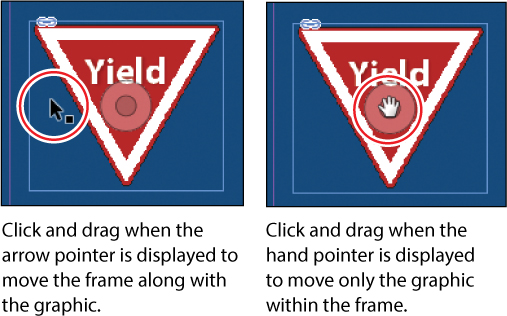
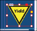
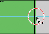
6 Using the Selection tool (![]() ), move the pointer within the Yield sign graphic. Notice the blue frame edge on the graphics frame. This blue border indicates that the frame is on the Text layer, which has been assigned a blue color. A transparent doughnut shape, otherwise known as the content grabber, is displayed in the center of the frame. When you move the pointer within the content grabber, it changes to a hand.
), move the pointer within the Yield sign graphic. Notice the blue frame edge on the graphics frame. This blue border indicates that the frame is on the Text layer, which has been assigned a blue color. A transparent doughnut shape, otherwise known as the content grabber, is displayed in the center of the frame. When you move the pointer within the content grabber, it changes to a hand.
7 Now move the pointer within the circular graphics frame below the Yield sign. Notice that this frame’s edge is red, the color assigned to the Graphics layer.
8 Move the pointer back to the frame with the Yield sign, make sure the arrow pointer is displayed, and then click within the graphics frame to select it.
In the Layers panel, you’ll notice that the Text layer is selected, and a small blue square appears to the right of the layer name. This indicates that the selected object belongs to this layer. You can move objects from one layer to another by dragging this square between layers in the panel.
![]() Tip
Tip
To see the position of the Yield sign in the Graphics layer relative to other objects in the layer, expand the Graphics layer by clicking the triangle to the left of the layer name.
9 In the Layers panel, drag the small blue square from the Text layer up to the Graphics layer, and then release the mouse button. The image now belongs to the Graphics layer and is now the topmost object on the top layer.

10 Click the empty layer lock box to the left of the Graphics layer to lock the layer.
11 Choose View > Fit Spread In Window.
Next, you will make a new layer and move existing content to it.
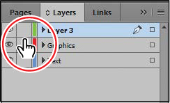
12 At the bottom of the Layers panel, click the Create New Layer button (![]() ). Because the Graphics layer was selected when you created the new layer, the new layer is positioned above the Graphics layer in the Layers panel.
). Because the Graphics layer was selected when you created the new layer, the new layer is positioned above the Graphics layer in the Layers panel.
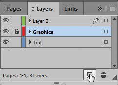
13 Double-click the name of the new layer (Layer 3) to open the Layer Options dialog box. Change the name to Background, and click OK.
![]() Tip
Tip
You can also rename a layer by selecting the layer in the Layers panel and then clicking its name.
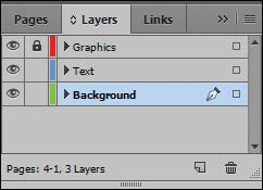
14 In the Layers panel, drag the Background layer to the bottom of the layer stack. A horizontal line appears when you move the pointer below the Text layer, indicating that the layer will be moved to the bottom when you release the mouse button.
15 Choose File > Save.
Creating and modifying text frames
In most cases, text is placed inside a frame. (You can also use the Type On A Path tool [![]() ] to flow text along a path.) The size and location of a text frame determine where the text appears on a page. Text frames can be created with the Type tool and can be modified using a variety of tools—as you’ll do in this part of the lesson.
] to flow text along a path.) The size and location of a text frame determine where the text appears on a page. Text frames can be created with the Type tool and can be modified using a variety of tools—as you’ll do in this part of the lesson.
Creating and resizing text frames
Now you’ll create your own text frame, adjust its size, and then resize another frame.
1 In the Pages panel, double-click the icon for page 4 to center it in the document window.
2 In the Layers panel, click the Text layer to select it. Any content created when the Text layer is selected will be placed on that layer.
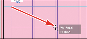
3 Select the Type tool (![]() ) in the Tools panel. Position the pointer where the left edge of the first column meets the horizontal guide at 22p0 on the vertical ruler. Drag to create a frame that snaps to the right edge of the second column and has a height of about 8p.
) in the Tools panel. Position the pointer where the left edge of the first column meets the horizontal guide at 22p0 on the vertical ruler. Drag to create a frame that snaps to the right edge of the second column and has a height of about 8p.
4 Use the Zoom tool (![]() ) to magnify the text frame, and then select the Type tool.
) to magnify the text frame, and then select the Type tool.
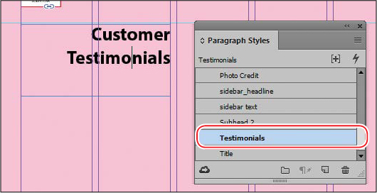
5 In the new text frame, type Customer, press Shift+Enter (Windows) or Shift+Return (Mac OS) to create a forced line break (without creating a new paragraph), and then type Testimonials. Click anywhere within the text to select the paragraph.
Now you’ll apply a paragraph style to the text.
6 Click the Paragraph Styles panel icon or choose Type > Paragraph Styles to open the panel. Click the style named Testimonials to apply it to the selected paragraph.
![]() Tip
Tip
It isn’t necessary to highlight an entire paragraph before applying a paragraph style to it. You can select a paragraph by clicking anywhere within it.
Read more about paragraph styles in Lesson 9, “Working with Styles.”
7 Using the Selection tool (![]() ), double-click the center-bottom handle of the selected text frame to fit the frame to the text vertically.
), double-click the center-bottom handle of the selected text frame to fit the frame to the text vertically.

8 Choose View > Fit Spread In Window, and then press Z to temporarily access the Zoom tool and magnify the rightmost column on the front page (page 1). Use the Selection tool (![]() ) to select the text frame below “the BUZZ.” The frame contains the text “NEW Day & Evening Classes.”
) to select the text frame below “the BUZZ.” The frame contains the text “NEW Day & Evening Classes.”
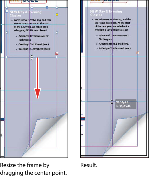
The red plus sign (+) at the lower-right corner of the text frame indicates that the frame contains overset text. Overset text is not visible because the frame is too small to display it. You’ll fix this by changing the size and shape of the text frame.
9 Drag the center-bottom handle of the selected text frame downward to resize the height of the frame until the bottom edge snaps to the ruler guide at 48p0 on the vertical ruler. When the pointer approaches the ruler guide, the arrows change in appearance from black to white, indicating that the frame edge is about to snap to the guide. The text remains overset. You’ll fix that later in this lesson.
10 Choose Edit > Deselect All, and then choose File > Save.
Using Smart Guides
• Align To Object Center. Causes object edges to snap to the center of other objects on a page or spread when you create or move an object.
• Align To Object Edges. Causes object edges to snap to the edge of other objects on a page or spread when you create or move an object.
• Smart Dimensions. Causes the width, height, or rotation of an object to snap to the dimensions of other objects on a page or spread when you create, resize, or rotate an object.
• Smart Spacing. Lets you quickly arrange objects so that the space between them is equal.
1 In the Tools panel, select the Rectangle Frame tool (![]() ). Click the left margin guide and drag to the right margin. As the pointer moves across the page, notice that a guide is displayed when the pointer reaches the middle of a column, the midpoint within a gutter, and the vertical center of the page. Release the mouse button when a Smart Guide appears.
). Click the left margin guide and drag to the right margin. As the pointer moves across the page, notice that a guide is displayed when the pointer reaches the middle of a column, the midpoint within a gutter, and the vertical center of the page. Release the mouse button when a Smart Guide appears.
2 With the Rectangle Frame tool still selected, click the top margin guide and drag downward to the bottom margin. Notice that when the pointer reaches the top edge, center, and bottom edge of the first object you created, as well as the horizontal center of the page, a Smart Guide appears.
3 In an empty area of the page, create one more object with the Rectangle Frame tool. Drag the mouse slowly and watch carefully. Smart Guides appear when the pointer reaches the edge or center of any of the other objects. Also, when the height or width of the new object equals the height or width of either of the other two objects, a vertical or horizontal (or both) line with arrows at both ends appears next to the object you’re creating and the object with the matching height or width.
4 Close the document without saving changes.
Reshaping a text frame
So far, you’ve resized a text frame with the Selection tool by dragging a handle. Now you’ll reshape the frame using the Direct Selection tool to move one of the frame’s anchor points.
1 In the Tools panel, select the Direct Selection tool (![]() ), and then click within the text frame you just resized. Four very small anchor points now appear at the corners of the selected text frame. The anchor points are all hollow, indicating that none of them is selected.
), and then click within the text frame you just resized. Four very small anchor points now appear at the corners of the selected text frame. The anchor points are all hollow, indicating that none of them is selected.
![]() Tip
Tip
To resize a text frame and the text characters inside it simultaneously, select the frame, and then double-click the Scale tool (![]() ), which is combined with the Free Transform, Rotate, and Shear tools in the Tools panel. You can then specify values in the Scale dialog box. You can also choose the Selection tool, hold down Shift+Ctrl (Windows) or Shift+Cmd (Mac OS), and drag a text frame handle. Including the Shift key ensures that the obect and content are scaled proportionally.
), which is combined with the Free Transform, Rotate, and Shear tools in the Tools panel. You can then specify values in the Scale dialog box. You can also choose the Selection tool, hold down Shift+Ctrl (Windows) or Shift+Cmd (Mac OS), and drag a text frame handle. Including the Shift key ensures that the obect and content are scaled proportionally.
2 Select the anchor point at the lower-left corner of the text frame, and pause for a moment until the arrow pointer turns black. Drag straight down until the point touches the margin guide at the bottom of the page and release the mouse button. As you drag, the text reflows simultaneously to give you a real-time view. After you release the mouse button, notice that the overset text indicator (the red plus sign) is no longer displayed, and all of the story’s text is now visible.
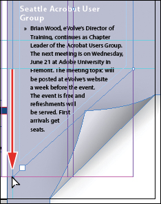
Be sure to drag only the anchor point—if you drag just above or to the right of the anchor point, you’ll move other corners of the text frame, too. If you accidentally move the frame, choose Edit > Undo Move and try again.
3 Press the V key to switch to the Selection tool.
Unselected anchor point.

Selected anchor point.
4 Deselect all objects, and then choose File > Save.
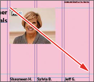
Creating multi-column text frames
Now you’ll take an existing text frame and convert it to a multiple-column text frame.
1 Choose View > Fit Spread In Window, and then use the Zoom tool (![]() ) to display the lower-right portion of the back page (page 4). Use the Selection tool (
) to display the lower-right portion of the back page (page 4). Use the Selection tool (![]() ) to select the text frame that begins with “Shauneen H.”
) to select the text frame that begins with “Shauneen H.”
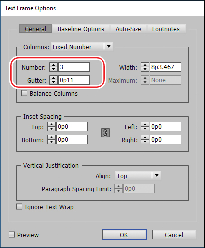
2 Choose Object > Text Frame Options. In the Text Frame Options dialog box, type 3 in the Number box and p11 (11 points) in the Gutter box if necessary. The gutter controls the distance between the columns. Click OK.
3 Choose Type > Show Hidden Characters to see the break characters. (If Hide Hidden Characters is displayed—rather than Show Hidden Characters—at the bottom of the Type menu, hidden characters are already showing.)
![]() Tip
Tip
You can also display hidden characters by choosing Hidden Characters from the View Options menu in the Application bar.
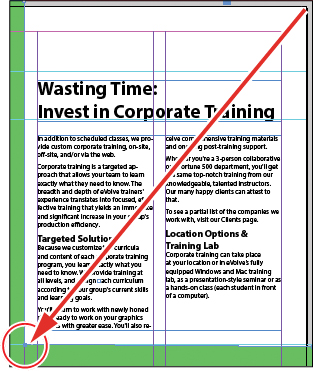
4 To begin each column with a heading, select the Type tool (![]() ), highlight the paragraph return at the end of the line before “Sylvia B.,” and then choose Type > Insert Break Character > Column Break. This forces “Sylvia B.” to the top of the second column. Insert a column break before the name “Jeff G.”
), highlight the paragraph return at the end of the line before “Sylvia B.,” and then choose Type > Insert Break Character > Column Break. This forces “Sylvia B.” to the top of the second column. Insert a column break before the name “Jeff G.”
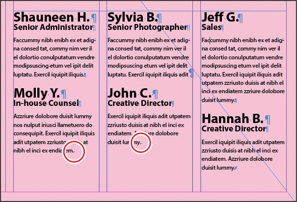
The small blue triangles within the red circles above are the Column Break characters.
5 Choose Type > Hide Hidden Characters.
Adjusting text inset and vertical alignment
You’ll now finish the red title bar on the cover by fitting the text nicely into the frame. By adjusting the space between the edge of the frame and the text, you make the text easier to read.
1 Choose View > Fit Spread In Window, and then use the Zoom tool (![]() ) to magnify the red text frame near the top of the front page (page 1) with the text “arrive smart. leave smarter.” Using the Selection tool (
) to magnify the red text frame near the top of the front page (page 1) with the text “arrive smart. leave smarter.” Using the Selection tool (![]() ), select the text frame with a red fill and white text at the top of the page.
), select the text frame with a red fill and white text at the top of the page.
2 Choose Object > Text Frame Options. If necessary, drag the Text Frame Options dialog box aside so that you can still see the selected text frame as you set options.
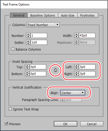
3 In the Text Frame Options dialog box, make sure that the Preview option in the lower-left corner of the Text Frame Options dialog box is selected. Then, in the Inset Spacing section, click the Make All Settings The Same icon (![]() ) to disable it so that you can change the Left setting independently. Change the Left value to 3p to move the left margin of the text frame 3 picas to the right and away from the left edge of the frame, and then change the Right value to 3p9.
) to disable it so that you can change the Left setting independently. Change the Left value to 3p to move the left margin of the text frame 3 picas to the right and away from the left edge of the frame, and then change the Right value to 3p9.
4 In the Vertical Justification section of the Text Frame Options dialog box, choose Center from the Align menu. Click OK.
5 Select the Type tool (![]() ), and then click to the left of “www.evolveseattle.com” to establish an insertion point. To move the URL text so that it aligns with the right inset you specified earlier, choose Type > Insert Special Character > Other > Right Indent Tab.
), and then click to the left of “www.evolveseattle.com” to establish an insertion point. To move the URL text so that it aligns with the right inset you specified earlier, choose Type > Insert Special Character > Other > Right Indent Tab.

6 Choose Edit > Deselect All, and then choose File > Save.
Creating and modifying graphics frames
Now you’re ready to add the company logo and the employees’ images to the spread. In this section, you’ll focus on different techniques for creating and modifying graphics frames and their contents.
Because you’ll be working on graphics rather than text, your first step is to make sure that the graphics appear on the Graphics layer rather than on the Text layer. Isolating objects on different layers streamlines your workflow and makes it easier to find and edit elements of your design.
Drawing a new graphics frame
To begin, you’ll create a frame for the logo at the top of the cover page (the page on the right in the first spread).
1 If the Layers panel is not visible, click the Layers panel icon or choose Window > Layers.
2 In the Layers panel, click the lock icon (![]() ) to unlock the Graphics layer. Lock the Text layer by clicking the box to the left of the layer name. Select the Graphics layer by clicking the name of the layer so that the new elements are assigned to this layer.
) to unlock the Graphics layer. Lock the Text layer by clicking the box to the left of the layer name. Select the Graphics layer by clicking the name of the layer so that the new elements are assigned to this layer.

3 Choose View > Fit Spread In Window, and then use the Zoom tool (![]() ) to zoom in on the upper-left corner of the front page (page 1).
) to zoom in on the upper-left corner of the front page (page 1).
4 In the Tools panel, select the Rectangle Frame tool (![]() ). Move the pointer to the corner where the top and left margin guides intersect, drag down until the pointer reaches the horizontal guide, and then drag across to the right edge of the first column.
). Move the pointer to the corner where the top and left margin guides intersect, drag down until the pointer reaches the horizontal guide, and then drag across to the right edge of the first column.
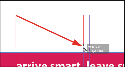
Drag to create a graphics frame.
5 Switch to the Selection tool (![]() ) and make sure that the graphics frame is still selected.
) and make sure that the graphics frame is still selected.
Placing a graphic within an existing frame
Now you’ll place the company logo within the selected frame.
1 Choose File > Place, and then double-click logo_paths.ai in the Links folder in the Lesson04 folder. The image appears in the graphics frame.
![]() Note
Note
If a graphics frame isn’t selected when you place an image, the pointer changes to the loaded graphics icon (![]() ). In this case, you could click within the graphics frame to place the image within the frame.
). In this case, you could click within the graphics frame to place the image within the frame.
2 To ensure that the graphic is displayed at the highest possible resolution, choose Object > Display Performance > High Quality Display.

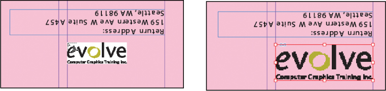
Resizing a graphics frame to crop a graphic
The graphics frame you created isn’t quite wide enough to show the entire logo, so you’ll widen it to reveal the hidden portion.
1 Using the Selection tool (![]() ), drag the center-right handle until the entire logo is visible. If you pause before you drag, you’ll be able to see the cropped portion of the image as you drag and easily determine when the frame edge is beyond the edge of the logo. Make sure you drag the small, white handle and not the larger, yellow one. The yellow handle lets you add corner options, and you’ll learn more about them later in this lesson.
), drag the center-right handle until the entire logo is visible. If you pause before you drag, you’ll be able to see the cropped portion of the image as you drag and easily determine when the frame edge is beyond the edge of the logo. Make sure you drag the small, white handle and not the larger, yellow one. The yellow handle lets you add corner options, and you’ll learn more about them later in this lesson.
![]() Tip
Tip
You can also reveal the cropped portion of the graphic by choosing Object > Fitting > Fit Frame To Content.

2 Choose Edit > Deselect All, and then choose File > Save.
Placing a graphic without an existing frame
The design of the newsletter uses two versions of the logo—one on the front cover and one on the back cover. You could simply use the logo you just placed and the Copy and Paste commands (Edit menu) to add the logo to the back cover, and you’ll do that later in this lesson, but instead you’ll import the logo graphic without first creating a graphics frame.
1 Choose View > Fit Spread In Window, and then use the Zoom tool (![]() ) to display the upper-right quarter of the back page (page 4).
) to display the upper-right quarter of the back page (page 4).
2 Choose File > Place, and then double-click logo_paths.ai in the Links folder in the Lesson04 folder. The pointer changes to a loaded graphics icon (![]() ) in the upper-left corner of a thumbnail of the graphic.
) in the upper-left corner of a thumbnail of the graphic.
3 Position the loaded graphics icon (![]() ) at the left edge of the rightmost column slightly below the rotated text frame that contains the return address. Drag until the pointer reaches the right edge of the column, and then release the mouse button. Notice that as you drag, a rectangle is displayed. This rectangle is proportional to the logo image.
) at the left edge of the rightmost column slightly below the rotated text frame that contains the return address. Drag until the pointer reaches the right edge of the column, and then release the mouse button. Notice that as you drag, a rectangle is displayed. This rectangle is proportional to the logo image.
You don’t need to resize the frame as you did earlier because the frame already shows the entire image. The graphic still needs to be rotated, but you’ll do that later in the lesson.
![]() Tip
Tip
If you click—rather than click and drag—an empty area of the page when you place an image, the image is placed at 100 percent of its original size. The upper-left corner of the image is placed where you click.
4 Choose Edit > Deselect All, and then choose File > Save.
Placing multiple graphics in a grid of frames
The back cover of the newsletter should contain six photos. You could place the photos one by one and then position each one individually, but because they will be arranged in a grid, you can place all the photos and arrange them in a grid at the same time.
1 Choose View > Fit Spread In Window.
2 Choose File > Place. Navigate to the Links folder in the Lesson04 folder, click the graphic file named 01ShauneenH.tif to select it, and then press Shift and click the file named 06HannahB.tif to select all six photos. Click Open.
3 Position the loaded graphics icon (![]() ) at the intersection of the horizontal ruler guide in the top half of the page and the left edge of the third column.
) at the intersection of the horizontal ruler guide in the top half of the page and the left edge of the third column.
4 Drag down and toward the right margin. As you drag, press the Up Arrow key once and the Right Arrow key twice. As you press the arrows, the proxy image changes to a grid of rectangles to indicate the layout of the grid.
![]() Tip
Tip
When using any of the frame creation tools (Rectangle, Polygon, Type, and so on), you can create multiple and equally spaced frames by using the same arrow key gestures as you drag with the tool.
5 Continue dragging until the pointer snaps to the intersection of the right margin guide and the lower horizontal ruler guide, and then release the mouse. A grid of six graphics frames displays the six photos you placed.

6 Choose Edit > Deselect All, and then choose File > Save.
Resizing and moving images within frames
Now that you’ve placed the six photos, you need to resize and reposition them so that they fill the graphics frames and are cropped correctly.
The image and the frame for any placed graphic are separate elements. Unlike text frames, a graphics frame and its content each have their own bounding box. Resizing the image (without resizing the frame) is exactly like resizing the frame and the image together, except that you first select the image’s bounding box before resizing it.
1 Using the Selection tool (![]() ), position the pointer over the content grabber within the image of Shauneen H. (the top-left photo). When the pointer is within the content grabber, a hand icon (
), position the pointer over the content grabber within the image of Shauneen H. (the top-left photo). When the pointer is within the content grabber, a hand icon (![]() ) is displayed. Click to select the frame’s contents (the image itself).
) is displayed. Click to select the frame’s contents (the image itself).
![]() Note
Note
If you want, you can use the Zoom tool to magnify the area you’re working on as you perform the tasks in this lesson.
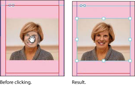
2 While holding down the Shift key, drag the center-bottom handle to the bottom edge of the graphics frame. Do the same with the center-top handle and drag it to the top edge of the frame. The Shift key maintains the proportions of the graphic so that it is not distorted. If you pause briefly before you start dragging, you’ll see a ghosted image of the cropped areas of the graphic contents—a feature called Dynamic Preview. Make sure that the image entirely fills the graphics frame.
![]() Tip
Tip
When resizing an image with the Selection tool, press Shift+Alt (Windows) or Shift+Option (Mac OS) to size the image proportionately from the center outward.
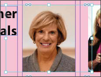
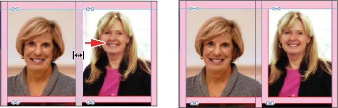
3 The image in the middle frame on the top row is too narrow to fill the frame. Click the content grabber with the Selection tool to select the image. While holding down the Shift key, drag the center-left handle to the left edge of the graphics frame. Do the same with the center-right handle and drag to the right edge of the frame. Make sure that the image entirely fills the graphics frame.
4 The image now fills the frame but is poorly cropped. To fix this, position the pointer over the content grabber within the image, and while holding down the Shift key, drag downward until the top of the photo aligns with the top of the frame.

5 Repeat step 2 for the remaining photo in the top row to fill the frame with the image.

You’ll use a different method to resize the other three photos.
6 Use the Selection tool to select the graphic on the left of the second row. You can select either the frame or its content.
7 Choose Object > Fitting > Fill Frame Proportionally. This increases the scale of the graphic so that the frame is filled. Small portions of the graphic are now cropped by the left and right edges of the frame.
![]() Tip
Tip
You can also access the fitting commands from the context menu by right-clicking (Windows) or Control-clicking (Mac OS), and you can click the fitting controls in the Control panel.
8 Repeat steps 6 and 7 for the remaining two photos in the bottom row.

9 Choose Edit > Deselect All, and then choose File > Save.
You can simultaneously resize a graphics frame and its content by selecting the frame (rather than the content) and holding down Shift+Ctrl (Windows) or Shift+ Command (Mac OS) as you drag a handle of the frame. The Shift key maintains the proportions of the bounding box so that the graphic is not distorted. Using the Shift key is optional if distorting the graphic doesn’t matter to your design.
Next, you’ll adjust the space between some of the photos to give the grid arrangement a visual tweak.
![]() Tip
Tip
If you enable the Auto-Fit option for a graphics frame, the image within will automatically resize when you resize the frame. To enable Auto-Fit for a selected graphics frame, choose Object > Fitting > Frame Fitting Options, and then select Auto-Fit or select Auto-Fit in the Control panel.
Adjusting the space between frames
The Gap tool (![]() ) lets you select and adjust the space between frames. You’ll use it to adjust the space between two of the photos in the top row and then two of the photos in the bottom row.
) lets you select and adjust the space between frames. You’ll use it to adjust the space between two of the photos in the top row and then two of the photos in the bottom row.
1 Choose View > Fit Page In Window. Hold down the Z key to temporarily access the Zoom tool (![]() ), zoom in on the two photos at the top left, and then release the Z key to return to the Selection tool.
), zoom in on the two photos at the top left, and then release the Z key to return to the Selection tool.
2 Select the Gap tool (![]() ), and then move the pointer into the vertical gap between the two pictures. The gap is highlighted—all the way down to the bottom of the two photos below.
), and then move the pointer into the vertical gap between the two pictures. The gap is highlighted—all the way down to the bottom of the two photos below.
3 Hold down the Shift key and drag the gap one gutter width to the right, making the graphics frame on the left one gutter width wider and the one on the right one gutter width narrower. (If you don’t hold Shift while dragging, you’ll move the gap between the two photos below as well.)
4 Choose View > Fit Page In Window. Press Z to temporarily access the Zoom tool, and then zoom in on the two photos on the bottom left.
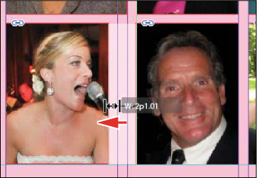
5 With the Gap tool, move the pointer to the vertical gap between the two pictures. Press Shift+Ctrl (Windows) or Shift+Command (Mac OS), and then drag to widen the gap from one gutter width to approximately three gutter widths. (You may have to drag left or right depending on which graphic you click closest to.) It’s important to release the mouse button before releasing the keys.
6 Choose View > Fit Page In Window, and then choose File > Save.
You’ve completed the grid of images on the back page (page 4).
Adding metadata captions to graphics frames
You can automatically generate captions for placed graphics based on metadata information stored in the original graphic files. Next, you’ll use the metadata captions feature to automatically add photographer credits to the pictures using metadata information.
![]() Tip
Tip
If Adobe Bridge is installed on your computer, the Metadata panel lets you easily edit metadata for images and see metadata associated with images.
InDesign lets you create either static captions, which generate caption text from a graphic’s metadata and must be updated manually, or live captions, which are variables that retain links to a graphic’s metadata and can be automatically updated.
1 With the Selection tool (![]() ), Shift-click to select the six graphics frames.
), Shift-click to select the six graphics frames.
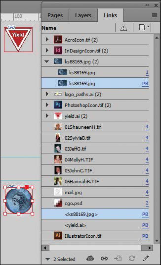
2 Click the Links panel icon to display the Links panel, and then choose Captions > Caption Setup from the panel menu.
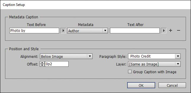
3 In the Caption Setup dialog box, specify the following settings:
• In the Text Before box, type Photo by. (Make sure to enter a space character after by. Don’t add a period after the space character.)
• Choose Author from the Metadata menu; leave the Text After box blank.
• Choose Below Image from the Alignment menu.
• Choose Photo Credit from the Paragraph Style menu.
• In the Offset box, enter p2.
![]() Tip
Tip
You can also open the Caption Setup dialog box by choosing Object > Captions > Caption Setup.
4 Click OK to save the settings and close the Caption Setup dialog box.
5 From the Links panel menu, choose Captions > Generate Static Captions.

Each of the graphic files contains a metadata element named “Author,” which stores the name of the photographer. This metadata information is used when the photo credit caption is generated.
6 Choose Edit > Deselect All, and then choose File > Save.
Placing and linking graphics frames
The two imported graphics on the cover page within the “IN THIS ISSUE” frame are used again on page 3 of the newsletter to accompany articles. Next, you’ll use the Place and Link feature to create copies of these two graphics and place them on page 3.
![]() Tip
Tip
In addition to placing and linking objects within a document, you can place and link objects between documents.
Unlike the Copy and Paste commands, which simply create a duplicate of the original object, the Place and Link feature creates a parent–child relationship between the original object and the copy. If you make changes to the parent object, you have the option to update the child object.
![]() Tip
Tip
You can also add objects to the Content Conveyor by selecting them and then choosing Edit > Place And Link.
1 Choose View > Fit Spread In Window.
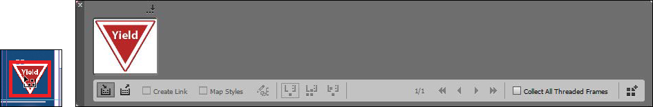
2 Select the Content Collector tool (![]() ). Notice that an empty Content Conveyor is now displayed at the bottom of the window.
). Notice that an empty Content Conveyor is now displayed at the bottom of the window.
3 Move the pointer over the Yield sign graphic on page 1. Notice that a heavy red border is displayed around the image, indicating that this graphics frame is on the Graphics layer. Click within the frame. The graphics frame is added to the Content Conveyor.
4 Click within the circular graphics frame below the Yield sign to add it to the Content Conveyor.

5 Open the Pages panel, and double-click page 3 to center it in the document window.
6 Select the Content Placer tool (![]() ). (It’s paired with the Content Collector tool in the Tools panel, and it’s also available in the lower-left corner of the Content Conveyor.) The pointer changes to a loaded graphics icon with the Yield sign graphic active. Both graphics are loaded.
). (It’s paired with the Content Collector tool in the Tools panel, and it’s also available in the lower-left corner of the Content Conveyor.) The pointer changes to a loaded graphics icon with the Yield sign graphic active. Both graphics are loaded.
![]() Note
Note
Creating a link when placing content not only creates a link to the parent graphic, but also links the object’s appearance. Link Options can be set from the Links panel menu.
7 Select Create Link at the lower-left corner of the Content Conveyor. If you don’t select Create Link, you will simply create copies of the original objects without any parent–child relationships.
8 Click the pasteboard to the right of the top article to place a copy of the Yield sign graphic, and then click the pasteboard to the right of the bottom article to place a copy of the circular graphic.
![]() Tip
Tip
When you select the Content Placer tool, it is loaded with all objects in the Content Conveyor. Press the arrow keys to move between objects in the Content Conveyor. To remove an object from the Content Conveyor, press Esc.
9 Press Esc or click the close box in the Content Conveyor to close it, or choose View > Extras > Hide Conveyor.
Modifying and updating parent–child graphics frames
Now that you’ve placed and linked the two graphics frames, you’ll see how the parent–child relationships work between the original objects and the copies.
1 Open the Links panel and adjust the panel so that all of the filenames of the imported graphics are visible in the scroll list. The selected circular graphic (<ks88169.jpg>) is highlighted in the list. The other graphic you placed and linked (<yield.ai>) is the next filename in the list. The greater than and less than characters (<>) that bracket the filenames indicate that these graphics are linked to parent objects. Notice that these two graphic files—the parent objects—are also listed higher up in the scroll list.
![]() Tip
Tip
A Smart Guide appears when the top of the circular graphics frame is aligned with the top of the text frame.
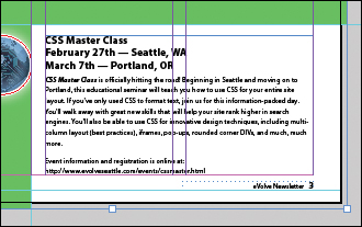
2 Use the Selection tool (![]() ) to position the circular graphics frame to the left of the “CSS Master Class” article. Align the top of the graphics frame with the top of the article’s text frame; align the right edge of the graphics frame with the column guide to the left of the article’s text frame.
) to position the circular graphics frame to the left of the “CSS Master Class” article. Align the top of the graphics frame with the top of the article’s text frame; align the right edge of the graphics frame with the column guide to the left of the article’s text frame.

3 Navigate to page 1 (the front cover page), and then select the circular graphics frame.
4 Use the Control panel to apply a 5-point white [Paper] stroke to the frame.
![A screenshot shows the "Control panel" being used to apply a 5-point white [Paper] stroke to the circular graphics frame.](http://images-20200215.ebookreading.net/17/2/2/9780134664446/9780134664446__adobe-indesign-cc__9780134664446__images__04fig43.jpg)
5 In the Links panel, notice that the status of the <ks88169.jpg> graphic on page 3 has changed to Modified (![]() ). That’s because its parent object has been modified.
). That’s because its parent object has been modified.
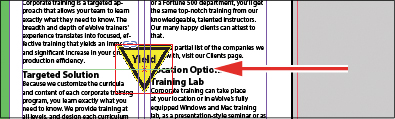
6 Navigate to page 3. Notice that the circular graphics frame no longer matches the version on the cover, and its link badge (the yellow triangle with the exclamation mark) also indicates it’s been modified. Select the circular graphics frame, and then click the Update Link button (![]() ) in the Links panel. The frame now matches its parent.
) in the Links panel. The frame now matches its parent.

![]() Tip
Tip
You can also click the modified link badge on the circular graphics frame on page 3 to update the link or double-click the modified link icon to the right of <ks88169.jpg> in the Links panel.
Next, you’ll replace the Yield sign graphic with a newer version and then update its child frame.
7 Navigate to page 1, and then select the red Yield sign graphic with the Selection tool.
8 Choose File > Place. Make sure Replace Selected Item is selected in the lower-left quadrant of the Place dialog box, and then double-click yield_new.ai in the Links folder in the Lesson04 folder.
In the Links panel, notice that the status of the file named <yield_new.ai> that’s on the pasteboard of page 3 is Modified. That’s because you replaced the parent graphic on page 1.
9 Select <yield_new.ai> in the scroll list, and then click the Update Link button (![]() ) in the Links panel. If you want, navigate to page 3 to see the updated graphic on the pasteboard, and then return to page 1.
) in the Links panel. If you want, navigate to page 3 to see the updated graphic on the pasteboard, and then return to page 1.
10 Click the pasteboard to deselect all objects, choose View > Fit Spread In Window, and then choose File > Save.
Changing the shape of a frame
When you resized a graphics frame using the Selection tool, the frame maintained its rectangular shape. Now you’ll use the Direct Selection tool and the Pen tool to reshape a frame on page 3 (the right page of the center spread).
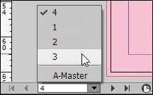
1 Choose 3 from the page box at the bottom of the document window. Choose View > Fit Page In Window.
2 Click the Layers panel icon, or choose Window > Layers. In the Layers panel, click the lock icon for the Text layer to unlock it, and click the Text layer to select it if it’s not selected.
Next, you’ll change the shape of a rectangular frame and, by doing so, change the background of the page.
3 Press the A key to switch to the Direct Selection tool (![]() ). Move the tip of the pointer over the right edge of the green frame that covers the page, and click when the pointer appears with a small diagonal line (
). Move the tip of the pointer over the right edge of the green frame that covers the page, and click when the pointer appears with a small diagonal line (![]() ). This selects the path and reveals the four anchor points and the center point of the frame. Leave the path selected.
). This selects the path and reveals the four anchor points and the center point of the frame. Leave the path selected.
4 Press the P key to switch to the Pen tool (![]() ).
).
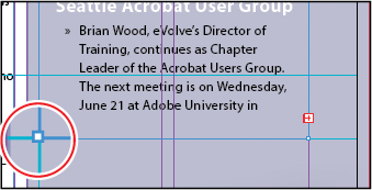
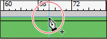
5 Carefully position the pointer over the top edge of the frame path where it intersects with the vertical ruler guide in the first column on page 3. When a plus sign is displayed at the lower right of the pointer, click. A new anchor point is added. The Pen tool automatically changes to the Add Anchor Point tool when it moves over an existing path.
6 Move the pointer to where the horizontal guide below the two-column text frame intersects with the bleed guide. Using the Pen tool, click again to add another new anchor point, and then choose Edit > Deselect All.
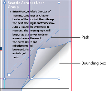
This point and the point you created in the previous step will form the corners of the irregular shape you’re creating. Repositioning the anchor point at the upper-right corner of the green frame will complete the reshaping of the frame.
7 Switch to the Direct Selection tool (![]() ). Click to select the upper-right corner point of the green frame. Drag the point down and to the left. (Pause before you drag so you can see the frame change as you drag.) When the anchor point snaps into place at the intersection of the right edge of the first column and the first horizontal guide from the top of the page (at 40p9 on the vertical ruler), release the mouse button.
). Click to select the upper-right corner point of the green frame. Drag the point down and to the left. (Pause before you drag so you can see the frame change as you drag.) When the anchor point snaps into place at the intersection of the right edge of the first column and the first horizontal guide from the top of the page (at 40p9 on the vertical ruler), release the mouse button.
The graphics frame is now properly shaped and sized for the design.
8 Choose File > Save.
Wrapping text around a graphic
With InDesign you can wrap text around the rectangular bounding box of any object, around objects of any shape, and around the contours of imported images. As you wrap text around the Yield sign in this exercise, you’ll see the difference between wrapping around its bounding box and around the shape of the graphic.
Your first task is to move the Yield sign graphic. For precise positioning, you can use the Smart Guides that are displayed dynamically when you create, move, or resize objects.
1 Using the Selection tool (![]() ), select the graphics frame with the image of a Yield sign on the pasteboard to the right of page 3. Make sure to click when the arrow pointer is displayed. If you click when the hand pointer is displayed, you’ll select the graphic instead of the graphics frame.
), select the graphics frame with the image of a Yield sign on the pasteboard to the right of page 3. Make sure to click when the arrow pointer is displayed. If you click when the hand pointer is displayed, you’ll select the graphic instead of the graphics frame.
2 Being careful not to select one of the handles, drag the frame to the left so that the center point of the frame is aligned with the center point of the text frame that contains the article text. When the two center points align, you should see a purple vertical Smart Guide and a green horizontal Smart Guide appear. When these guidelines appear, release the mouse button.
Make sure that you have moved the frame onto the page without changing its size. Notice that the graphic overlaps the text. You’ll change this by applying a text wrap.
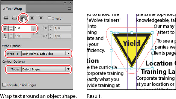
3 Use the Zoom tool to zoom in on the frame you just moved. Choose Window > Text Wrap. In the Text Wrap panel, select Wrap Around Bounding Box (![]() ) to wrap the text around the bounding box rather than around the Yield graphic’s shape. If necessary, choose Show Options from the panel menu to display all of the controls in the Text Wrap panel.
) to wrap the text around the bounding box rather than around the Yield graphic’s shape. If necessary, choose Show Options from the panel menu to display all of the controls in the Text Wrap panel.
This option leaves too much white space for your desired design, so you’ll try another Text Wrap option.
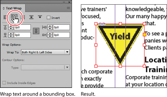
4 Select Wrap Around Object Shape (![]() ). In the Wrap Options section, choose Both Right & Left Sides from the Wrap To menu if it isn’t already selected. In the Contour Options section, choose Detect Edges from the Type menu. Enter 1p in the Top Offset box to add space between the edge of the graphic and the text, and press Enter or Return. Click a blank area to deselect all, or choose Edit > Deselect All.
). In the Wrap Options section, choose Both Right & Left Sides from the Wrap To menu if it isn’t already selected. In the Contour Options section, choose Detect Edges from the Type menu. Enter 1p in the Top Offset box to add space between the edge of the graphic and the text, and press Enter or Return. Click a blank area to deselect all, or choose Edit > Deselect All.
![]() Note
Note
The Wrap To menu in the Text Wrap panel is available only if you select Wrap Around Bounding Box or Wrap Around Object Shape at the top of the panel.
5 Close the Text Wrap panel, and choose File > Save.
Modifying the shape of frames
In this section, you’ll use various features that allow you to create nonrectangular frames. To begin, you’ll subtract the area of one shape from another. After that, you’ll create a polygon-shaped frame, and then you’ll add rounded corners to a frame.
Working with compound shapes
You can change the shape of an existing frame by adding other shapes to or subtracting other shapes from its area. The shape of a frame can also be changed, even if the frame already contains text or graphics. Now you’ll subtract a shape from the green background on page 3 to create a white background for the article at the bottom of the page.
1 Choose View > Fit Page In Window to fit and center page 3 in the document window.
2 Using the Rectangle Frame tool (![]() ), draw a frame from where the right edge of the first column meets the horizontal guide at 46p6 on the vertical ruler to the intersection of the bleed guides that meet outside the lower-right corner of the page.
), draw a frame from where the right edge of the first column meets the horizontal guide at 46p6 on the vertical ruler to the intersection of the bleed guides that meet outside the lower-right corner of the page.
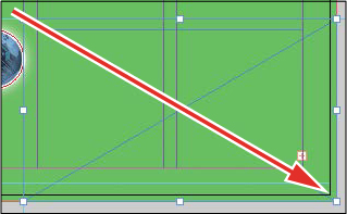
Draw a rectangle, and snap to the bleed guide corner.
3 With the Selection tool (![]() ), hold down the Shift key and click the green shape you modified earlier (outside of the frame you just created) that covers a good part of page 3 to simultaneously select the new rectangle and the green box. Two frames are now selected.
), hold down the Shift key and click the green shape you modified earlier (outside of the frame you just created) that covers a good part of page 3 to simultaneously select the new rectangle and the green box. Two frames are now selected.
4 Choose Object > Pathfinder > Subtract to subtract the top shape (the new rectangle) from the green shape. The text frame at the bottom of the page is now on a white background.
5 With the green box still selected, choose Object > Lock. This helps avoid accidental repositioning of the frame.
![]() Tip
Tip
A lock icon (![]() ) is displayed in the upper-left corner of a locked frame. Clicking the icon unlocks the frame. If a lock icon is not visible on a locked object, choose View > Extras > Show Frame Edges.
) is displayed in the upper-left corner of a locked frame. Clicking the icon unlocks the frame. If a lock icon is not visible on a locked object, choose View > Extras > Show Frame Edges.
Creating polygons and converting shapes
You can use the Polygon tool (![]() ) or the Polygon Frame tool (
) or the Polygon Frame tool (![]() ) to create regular polygons with however many sides you want. You can also change the shape of an existing frame, even if the frame already contains text or graphics. You’ll try this out by creating an octagonal frame, placing a graphic within it, and then resizing the frame.
) to create regular polygons with however many sides you want. You can also change the shape of an existing frame, even if the frame already contains text or graphics. You’ll try this out by creating an octagonal frame, placing a graphic within it, and then resizing the frame.
1 Click the Layers panel icon or choose Window > Layers to open the Layers panel.
2 Click the Graphics layer to select it.
3 Select the Polygon Frame tool (![]() ) in the Tools panel. It’s grouped with the Rectangle Frame tool (
) in the Tools panel. It’s grouped with the Rectangle Frame tool (![]() ) and the Ellipse Frame tool (
) and the Ellipse Frame tool (![]() ).
).
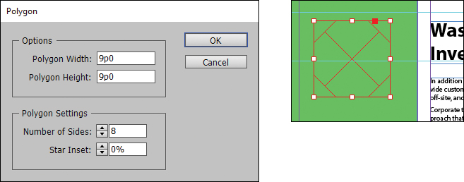
4 Click on page 3 to the left of the headline that begins “Wasting Time:”. In the Polygon dialog box, change Polygon Width and Polygon Height to 9p, change Number Of Sides to 8, and then click OK.
5 With the polygon shape selected, choose File > Place, and select stopsign.tif in the Links folder in the Lesson04 folder. Click Open.
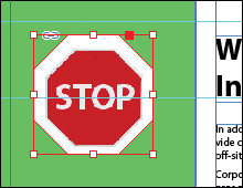
6 Use the Zoom tool (![]() ) to zoom in on the graphic, and then choose Object > Display Performance > High Quality Display to display the graphic as clearly as possible.
) to zoom in on the graphic, and then choose Object > Display Performance > High Quality Display to display the graphic as clearly as possible.
7 Using the Selection tool (![]() ), drag the midpoint handle on the top of the graphics frame downward until the frame crops the white and gray area above the red portion of the Stop sign. Drag the three other midpoint handles so that all of the surrounding area is cropped and only the red of the Stop sign is visible.
), drag the midpoint handle on the top of the graphics frame downward until the frame crops the white and gray area above the red portion of the Stop sign. Drag the three other midpoint handles so that all of the surrounding area is cropped and only the red of the Stop sign is visible.
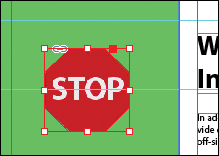
8 Choose View > Fit Page In Window, and then use the Selection tool (![]() ) to move the frame so that the bottom of the letters in the “STOP” sign align with the bottom of the “Wasting Time:” headline to the right. Its right edge will be approximately one gutter width to the left of the right edge of the green background frame. Pause briefly before dragging to display the graphic as you drag.
) to move the frame so that the bottom of the letters in the “STOP” sign align with the bottom of the “Wasting Time:” headline to the right. Its right edge will be approximately one gutter width to the left of the right edge of the green background frame. Pause briefly before dragging to display the graphic as you drag.

Adding rounded corners to frames
Next, you’ll modify a text frame by rounding its corners.
1 Choose 1 from the page box at the bottom of the document window. Choose View > Fit Page In Window.
2 With the Selection tool (![]() ) still selected, hold down the Z key to temporarily access the Zoom tool (
) still selected, hold down the Z key to temporarily access the Zoom tool (![]() ), zoom in on the dark blue text frame on page 1, and then release the Z key to return to the Selection tool.
), zoom in on the dark blue text frame on page 1, and then release the Z key to return to the Selection tool.
3 Select the dark blue text frame, and then click the small yellow square that’s slightly below the resizing handle at the upper-right corner of the frame. Four small yellow diamonds replace the four resizing handles at the corners of the frame.
![]() Tip
Tip
If the yellow square is not visible when selecting the frame, choose View > Extras > Show Live Corners. Also ensure that Screen Mode is set to Normal (View > Screen Mode > Normal).
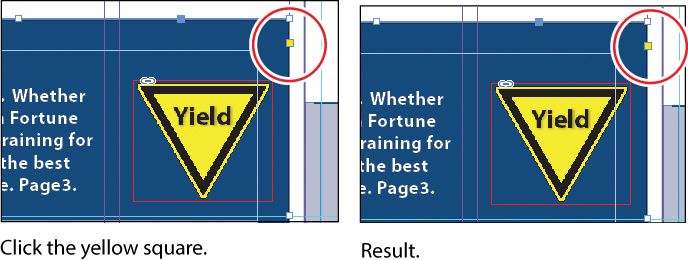
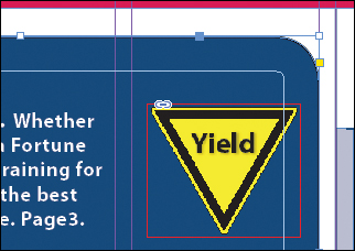
4 Drag the diamond at the upper-right corner of the frame to the left and release the mouse button when the live radius (R:) value is approximately 2p0. As you drag, the other three corners change, too. (If you hold down the Shift key when dragging, only the corner you are working on changes.)
![]() Tip
Tip
After you create rounded corners, you can Alt-click (Windows) or Option-click (Mac OS) any of the diamonds to cycle through several different corner effects.
5 Choose Edit > Deselect All to exit live corner edit mode, and then choose File > Save.
Transforming and aligning objects
Various tools and commands in InDesign let you modify an object’s size or shape and change its orientation on the page. All transformations—rotating, scaling, shearing, and flipping—are available in the Transform and Control panels, where you can precisely specify transformations. You can also align or distribute objects horizontally or vertically along the selection, margins, page, or spread.
You’ll experiment with some of these features now.
Rotating an object
InDesign offers several methods for rotating objects. In this part of the lesson, you’ll use the Control panel to rotate one of the logos you imported earlier in the lesson.
1 Use either the page box at the bottom of the document window or the Pages panel to display page 4 (the first page of the document; the back page of the newsletter). Choose View > Fit Page In Window.
2 Using the Selection tool (![]() ), select the “evolve” logo you imported earlier in the lesson. (Make sure you select the graphics frame and not the graphic within.)
), select the “evolve” logo you imported earlier in the lesson. (Make sure you select the graphics frame and not the graphic within.)
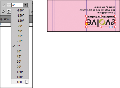
3 At the left end of the Control panel, make sure that the center point is selected on the Reference Point locator (![]() ) so that the object rotates around its center. Choose 180° from the Rotation Angle menu in the Control panel.
) so that the object rotates around its center. Choose 180° from the Rotation Angle menu in the Control panel.
Rotating an image within its frame
You can rotate the content of a graphics frame with the Selection tool.
![]() Tip
Tip
You can also rotate a selected object by choosing Object > Transform > Rotate and entering a value in the Angle field of the Rotate dialog box.
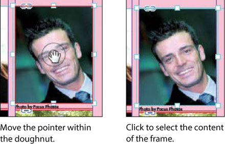
1 Using the Selection tool (![]() ), select the image of Jeff G. (top right) by clicking within the content grabber. The arrow pointer changes to a hand when it’s within the doughnut shape.
), select the image of Jeff G. (top right) by clicking within the content grabber. The arrow pointer changes to a hand when it’s within the doughnut shape.
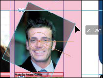
2 Move the pointer slightly outside the resizing handle at the upper-right corner of the picture. The rotate pointer (![]() ) is displayed.
) is displayed.
3 Click and drag clockwise to rotate the image until the head is approximately vertical (about –25°), and then release the mouse button. As you drag, the angle of rotation is displayed along with the image.
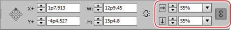
4 In the Control panel, make sure that the center point is selected in the reference point locator (![]() ).
).
5 After being rotated, the image no longer fills the frame. To fix this, first make sure that the Constrain Proportions For Scaling icon (![]() ) to the right of the Scale X Percentage and Scale Y Percentage boxes in the Control panel is selected, and then enter 55 in the Scale X Percentage box and press Enter or Return.
) to the right of the Scale X Percentage and Scale Y Percentage boxes in the Control panel is selected, and then enter 55 in the Scale X Percentage box and press Enter or Return.
6 Choose Edit > Deselect All, and then choose File > Save.
Aligning multiple objects
Precise alignment is made easy when you use the Align panel. Next, you’ll use the Align panel to horizontally center multiple objects on a page, and then you’ll align multiple images.
1 Choose View > Fit Page In Window, and then choose page 2 in the page box at the bottom of the document window.
2 Using the Selection tool (![]() ), click the text frame at the top of the page containing the “Partial Class Calendar” text and Shift-click the “evolve” logo above it. (Unlike the two logos you imported earlier, this logo was created within InDesign and is a group of objects. You’ll work with this group later in the lesson.)
), click the text frame at the top of the page containing the “Partial Class Calendar” text and Shift-click the “evolve” logo above it. (Unlike the two logos you imported earlier, this logo was created within InDesign and is a group of objects. You’ll work with this group later in the lesson.)
3 Choose Window > Object & Layout > Align to open the Align panel.
4 In the Align panel, choose Align To Page from the Align To menu, and then click the Align Horizontal Centers button (![]() ). The objects are now aligned to the center of the page.
). The objects are now aligned to the center of the page.
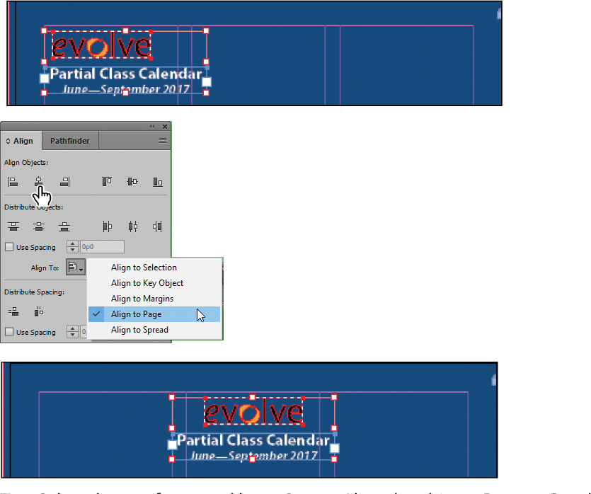
Top: Select the text frame and logo. Center: Align the objects. Bottom: Result.
5 Click a blank area or choose Edit > Deselect All.
6 Use the scroll bar at the bottom of the document window to show more of the pasteboard on the left of page 2. You’ll see seven software application icons.
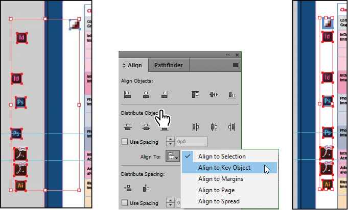
7 Using the Selection tool (![]() ), select the graphics frame at the upper-left corner of the calendar, and then Shift-click to select the seven graphics frames.
), select the graphics frame at the upper-left corner of the calendar, and then Shift-click to select the seven graphics frames.
8 In the Align panel, choose Align To Key Object from the Align To menu. Notice that the first graphics frame you selected now has a thick blue border, indicating it’s the key object.
![]() Note
Note
When you specify a key object, the alignment of the other selected objects will be relative to the key object’s position.
9 Click the Align Right Edges button (![]() ).
).
![]() Tip
Tip
InDesign automatically assigns the object you selected first as the key object. To change the key object once you’ve selected all objects to be aligned, click the object that should be the key object. A thicker selection border will then appear around that object.
10 Choose Edit > Deselect All, and then choose File > Save.
Scaling multiple objects
InDesign lets you scale multiple selected objects.
Next you’ll select two of the icons and resize both of them at once.
1 Use the Zoom tool (![]() ) to zoom in on the two Acrobat icons on the left side of the page.
) to zoom in on the two Acrobat icons on the left side of the page.
2 Using the Selection tool (![]() ), click the first of the icons to select it, and then Shift-click the second icon to select both.
), click the first of the icons to select it, and then Shift-click the second icon to select both.
3 Press Shift+Ctrl (Windows) or Shift+Command (Mac OS), and then drag the handle at the upper-left corner down and to the right to make the two icons the same width as the Adobe Photoshop icon above or the Adobe Illustrator icon below the selected icons. A Smart Guide is displayed when the left edges of the selected frames align with the frame above.
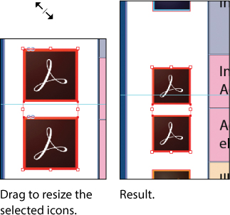
4 Choose Edit > Deselect All, and then choose File > Save.
Selecting and modifying grouped objects
Earlier you aligned the “evolve” logo at the top of page 2 to the center of the page. Now you’ll change the fill color of some of the logo’s shapes. Because they’re grouped, you can select and modify them as a unit. You’ll now change the fill color of just a few of the shapes without ungrouping or changing the other objects of the group.
The Direct Selection tool, or a set of commands in the Object menu (Object > Select), lets you select individual objects in a grouped object.
1 Choose View > Fit Spread In Window.
2 With the Selection tool (![]() ), click the “evolve” group at the top of page 2. If you want, use the Zoom tool (
), click the “evolve” group at the top of page 2. If you want, use the Zoom tool (![]() ) to magnify the area you’re working on.
) to magnify the area you’re working on.
3 Click the Select Content button (![]() ) in the Control panel to select one object in the group without ungrouping.
) in the Control panel to select one object in the group without ungrouping.
![]() Tip
Tip
You can also select an object in a group by double-clicking the object with the Selection tool, by selecting the group and choosing Object > Select > Content, or by right-clicking (Windows) or Control-clicking (Mac OS) the group and choosing Select > Content from the context menu.

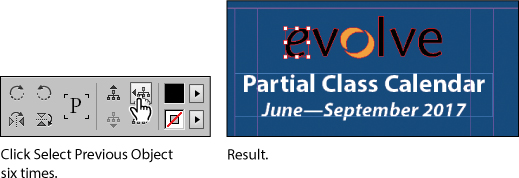
4 Click the Select Previous Object button (![]() ) in the Control panel six times to select the first “e” in the word “evolve.” Note that the Select Next Object button selects in the opposite direction.
) in the Control panel six times to select the first “e” in the word “evolve.” Note that the Select Next Object button selects in the opposite direction.
5 Using the Direct Selection tool (![]() ), hold down the Shift key and click the “v,” “l,” “v,” and “e” letters in the logo to simultaneously select them.
), hold down the Shift key and click the “v,” “l,” “v,” and “e” letters in the logo to simultaneously select them.
6 Click the Swatches panel icon or choose Window > Color > Swatches. Click the Fill box at the top of the Swatches panel and choose [Paper] to fill the letter shapes with a white color.
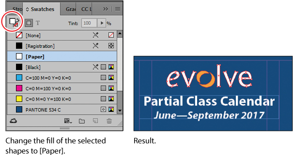
7 Choose Edit > Deselect All, and then choose File > Save.
Creating a QR code
InDesign lets you quickly generate and edit high-quality quick response (QR) code graphics. QR codes are machine-readable printed representations of data for various industry uses and have become common in consumer advertising. A consumer with a smartphone can install a QR-code scanner app that can read and decode the URL information and redirect the phone’s browser to a company website. After scanning QR codes, users may receive text, add a business card contact to their devices, open a web hyperlink, or compose an email or text message.
The QR code generated in InDesign is a high-fidelity graphic object that behaves exactly like other InDesign objects. You can easily scale the object and fill it with color, apply transparency effects, or copy and paste the object as a vector graphic into a standard graphics editor tool such as Adobe Illustrator.
Next, you’ll add a QR code to the back page of the newsletter and configure it to open a web page.
1 Navigate to page 4 of the document (the back cover), and then choose View > Fit Page In Window to center the page.
2 Choose Object > Generate QR Code.
3 Choose each of the options in the Type menu to view the associated controls, and then choose Web Hyperlink.
![]() Tip
Tip
Click the Color tab in the Generate QR Code dialog box to apply a swatch color to the code.
![]() Tip
Tip
To edit a QR code, right-click (Windows) or Control-click (Mac OS) the code with the Selection tool, and then choose Edit QR Code from the context menu or choose Object > Edit QR Code.
4 In the URL field, enter http://www.adobe.com (or the complete URL for any website you want).
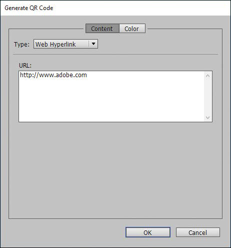
5 Click OK to close the dialog box.
6 Click the intersection of the margin guides at the lower-left corner of the page, and then drag upward until the edge of the frame aligns with the first column guide.
Drawing lines and modifying arrowheads
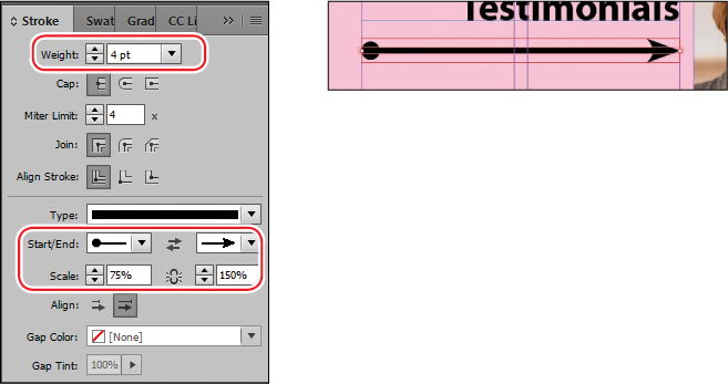
InDesign CC (2017 Release) introduces a new line-related capability: the ability to scale arrowheads independently of line size. Next, you’ll use this new feature to complete the design of the newsletter.
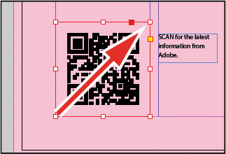
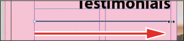
1 Select the Line tool (![]() ). Position the pointer on the left margin guide on page 4, slightly below the text frame with the “Customer Testimonials” text.
). Position the pointer on the left margin guide on page 4, slightly below the text frame with the “Customer Testimonials” text.
2 While pressing the Shift key, drag horizontally from the left margin guide to the vertical column guide at the right of the second column.
3 Click the Stroke panel icon or choose Window > Stroke to open the Stroke panel. Choose 4 from the Weight menu, CircleSolid from the Start Arrowhead menu, and Curved from the End Arrowhead menu.
4 Make sure Link Start And End Arrowhead Scales is not selected (![]() ) so that you can independently scale the start and end arrowheads. Enter 75 in the Scale Factor For Start Arrowhead box; enter 150 in the Scale Factor For End Arrowhead box, and press Enter or Return.
) so that you can independently scale the start and end arrowheads. Enter 75 in the Scale Factor For Start Arrowhead box; enter 150 in the Scale Factor For End Arrowhead box, and press Enter or Return.
![]() Tip
Tip
In addition to adding arrowheads to straight lines created with the Line tool, you can also add arrowheads to curved lines created with the Pen tool.
5 Choose File > Save.
Finishing up
Now it’s time to admire your work.
1 Choose Edit > Deselect All.
2 Choose View > Fit Spread In Window.
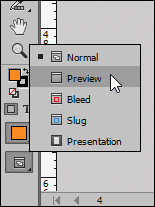
3 At the bottom of the Tools panel, hold down the current screen mode button (![]() ) and choose Preview from the menu that appears. Preview mode is an ideal way to see what a document will look like when printed. Preview mode displays artwork as if it were output, with all nonprinting elements suppressed (grids, guides, frame edges, nonprinting objects) and the pasteboard set to the preview color defined in Preferences.
) and choose Preview from the menu that appears. Preview mode is an ideal way to see what a document will look like when printed. Preview mode displays artwork as if it were output, with all nonprinting elements suppressed (grids, guides, frame edges, nonprinting objects) and the pasteboard set to the preview color defined in Preferences.
4 Press the Tab key to close all the panels at the same time. Press the Tab key again when you are ready to show all the panels.
5 Choose File > Save.
Congratulations. You have finished the lesson.
Exploring on your own
One of the best ways to learn about frames is to experiment on your own.
In this section, you’ll learn how to nest an object inside a frame. Follow these steps to learn more about selecting and manipulating frames:
1 Create a new (Print) document using the default settings in the New Document dialog box.
2 Use the Ellipse Frame tool (![]() ) to create a small circular text frame, approximately 12p0 x 12p0. (Press the Shift key as you drag to constrain the shape to a circle.)
) to create a small circular text frame, approximately 12p0 x 12p0. (Press the Shift key as you drag to constrain the shape to a circle.)
3 Select the Type tool and then click within the frame to convert it to a text frame.
4 Choose Type > Fill With Placeholder Text to fill the frame with text.
5 Press the Esc key to switch to the Selection tool, and then use the Swatches panel to apply a fill color to the text frame.
6 Select Edit > Deselect All, and then select the Polygon tool (![]() ). Draw a shape on the page. (Before creating the polygon, you can double-click the Polygon tool to specify the number of sides and optionally a star inset value if you want to create a starburst shape.)
). Draw a shape on the page. (Before creating the polygon, you can double-click the Polygon tool to specify the number of sides and optionally a star inset value if you want to create a starburst shape.)
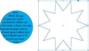
7 Using the Selection tool (![]() ), select the text frame you created earlier, and then choose Edit > Copy.
), select the text frame you created earlier, and then choose Edit > Copy.
8 Select the polygon frame, and then choose Edit > Paste Into to nest the text frame inside the polygon frame. (If you choose Edit > Paste, the copied text frame is not pasted inside the selected frame.)
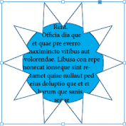
9 Use the Selection tool to move the text frame by positioning the pointer within the content grabber in the center of the polygon frame and then dragging.
10 Use the Selection tool to move the polygon frame and its content by positioning the pointer outside the content grabber and then dragging.
11 Choose Edit > Deselect All.
12 Use the Direct Selection tool (![]() ) to select the polygon frame, and then drag any of the handles to change the shape of the polygon.
) to select the polygon frame, and then drag any of the handles to change the shape of the polygon.
13 When you have finished experimenting, close the document without saving.
Review questions
1 When should you use the Selection tool to select an object, and when should you use the Direct Selection tool to select an object?
2 How do you resize a graphics frame and its content simultaneously?
3 How do you rotate the graphic within a graphics frame without rotating the frame?
4 Without ungrouping objects, how do you select an object within a group?
Review answers
1 Use the Selection tool for general layout tasks, such as positioning, rotating, and resizing objects. Use the Direct Selection tool for tasks involving editing paths or frames, such as moving an anchor point on a path or selecting an object within a group and then changing the object’s fill or stroke color.
2 To resize a graphics frame and its content simultaneously, select the frame with the Selection tool, hold down Shift+Ctrl (Windows) or Shift+Command (Mac OS), and then drag a handle. This keyboard combination ensures that objects and contents will be scaled proportionally. (If you don’t include the Shift key while dragging, the object’s and content’s proportions are not maintained.) Alternatively, you can enable the Auto-Fit feature for a selected graphics frame and resize it without the need to hold down the Ctrl (Windows) or Command (Mac OS) key.
3 To rotate a graphic within a frame, use the Selection tool to select the graphic within the frame by clicking within the content grabber. Then position the pointer slightly outside any of the four corner handles and drag to rotate the graphic. Add the Shift key while dragging to constrain rotation to increments of 45°. You can also rotate a selected graphic by changing the Rotation Angle value in the Control panel.
4 To select an object within a group, use the Selection tool (![]() ) to select the group, and then click the Select Content button (
) to select the group, and then click the Select Content button (![]() ) in the Control panel to select one object in the group. You can then click the Select Previous Object or Select Next Object button to select different objects in the group. You can also select an object in a group by clicking the object with the Direct Selection tool (
) in the Control panel to select one object in the group. You can then click the Select Previous Object or Select Next Object button to select different objects in the group. You can also select an object in a group by clicking the object with the Direct Selection tool (![]() ) or double-clicking it with the Selection tool.
) or double-clicking it with the Selection tool.