Chapter 4. Balancing the Software System Use Case Model
Use cases alone are not enough to carry you into design. The temptation is to base development on use cases, especially to developers who come from a transaction-oriented background. The results are usually enormous control objects, no reuse of functionality, and duplication of objects.
—Anthony Heritage and Phil Coley [Heritage 1995]
What’s in this chapter?
Use cases can describe the functionality of the system, but form is necessary to balance functionality. Form is provided with a well-designed system architecture. In this chapter, we discuss the ways that architecture can enhance the use case model.
Use case modeling, when used in isolation and performed incorrectly, may lead to certain types of problems. First, use cases can be utilized to specify many different kinds of software systems; they are a conceptualization of the way a particular system will be used. The specified system can then be implemented using a variety of programming languages such as object-oriented (Java, C++, Smalltalk, or Eiffel), structured (C, Pascal, or COBOL), or functional (Lisp or Prolog). Use cases are most often used to describe systems created using object-oriented technology; after all, use cases were invented in the context of an object-oriented methodology.
The ability to represent many different software technologies presents a problem. While the world is full of objects and they represent a nice way to categorize software elements, traditional work is done in a more functional manner. As use cases map work onto a model of cooperating objects, they represent functional stripes across the objects. Representing systems as functional stripes maps well to the structured and functional programming paradigm but could drive an object model in the functional direction. A potential risk of utilizing the use case model to drive object-oriented development is the possibility of ending up with a functional model instead of an object model [Firesmith 1995]. This risk is greater for developers with less experience with object-oriented development. However, experienced software developers have fallen prey to the problem as well.
A second problem arises in modeling large systems with use cases. Developing large use case models can be a lesson in understanding how many different views of a system there can be. As the number of use case developers increases, so does the number of natural deviations from a common vocabulary and common understanding. Each developer approaches the description of a system with individual bias. Use cases authored by different developers may describe the same thing differently. Synonyms and homonyms requiring interpretation by the original author creep in. The result is a disjoint use case model and frustration in realizing the system in subsequent steps.
Finally, defining the task of the system is a common problem in the conceptualization and specification of systems [Jacobson 1992]. There can be many different ways users can sort through the system (see the Interesting Issue box on page 47). Another common difficulty is understanding where to stop. An inconsistent or undefined system boundary is the number one problem in use case modeling [Lilly 1999].
Jacobson realized the possible problems when he introduced use case analysis [Jacobson 1992]. He advocated three concurrent initiatives to balance the use case model (Figure 4-1). The first is the use of domain analysis, a technique for developing an initial object model.
Figure 4-1. Three concurrent initiatives to balance the use case model
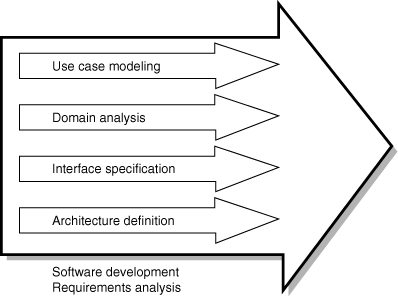
The second technique is interface specification. Interface specification documents the interactions with external entities, the actors. Finally, architecture definition allows us to logically decompose systems into subsystems and components. Nonfunctional requirements can also be addressed in this definition. This chapter examines each of these activities and their ability to reduce some of the possible risks in use case modeling.
Analyzing the Domain
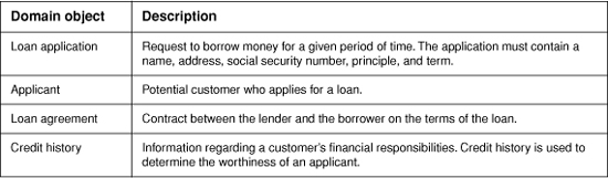
Creating a common vocabulary to be used across the use case model is a very important task. A common vocabulary keeps use case developers focused on the right level of use case to be written. The vocabulary should reflect tangible objects in the domain germane to the system being developed. For example, in the loan application system, possible objects are “loan application,” “applicant,” “loan agreement,” and “credit history.” As there may be many semantic pitfalls in creating this vocabulary (such as differentiating between a loan application and a loan request), domain understanding is critical to the success of this activity.
The result of this activity (called domain analysis) is a system glossary or domain object model. What’s in the system glossary can range from a simple name–definition format (Figure 4-2) to a full-fledged analysis object model complete with associations between the objects. Creating the glossary is an iterative process. As new use cases are found, new entries may be made in the glossary. Similarly, the glossary should serve as a reference for writers of use cases. When changes are made in use cases, the glossary should be updated for accuracy and completeness.
Figure 4-2. Simple system glossary for a loan application system
A good way to start a system glossary is to extract the applicable objects from the business glossary,1 if one exists. This is one way that advanced use case modeling for business process development feeds the software system development process. Using the terms from the business glossary ensures consistency between the business and the systems that aid it. Other inputs to the system glossary might include the vision document, interviews, other required documents, domain experts, and discussions.
The system glossary can also contain information about objects beyond the information in a use case. It might contain formulas, calculations, or business rules that would not be found in a use case but might constrain the way the use case is written. For example, certain personal information (name, social security number, and address) is mandatory on all loan applications. This requirement could be spelled out in each use case or found in the glossary.
When domain analysis is performed in conjunction with use case modeling, it reduces the risk of a functional design. (See the Interesting Issue box on page 47.) Domain analysis pinpoints the language to be used to create textual descriptions in the use cases. It enforces, in some sense, an object-oriented approach by calling out the objects as the use cases are written. We will discuss the glossary and its role in use case development further in Chapter 8.
Domain analysis is one of many techniques designed to aid in the definition of the system boundary. Since objects in the system glossary have tangible value in the system domain, it is easy to see whether they are germane to the problems the system attempts to solve. Reviewing the system glossary can yield objects that fall outside the scope of the system. Objects outside the system boundary may appear in the system glossary, but it should be noted that they are outside the system boundary. These objects may be part of the services that other systems provide or part of a larger business process. When writing a use case, be careful with these objects, as they may cause you to increase the scope or build a solution that encompasses an area greater than necessary.
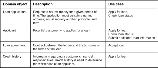
For traceability reasons, a third column may be added to the simple system glossary with the names of use cases that act on the object (Figure 4-3). Use case names can be added to this column as the use cases are identified (if it is obvious) or when the base or initial use case descriptions are written (see Chapters 7 and 8). Traceability can be helpful in the later stages of architectural development and design when objects are partitioned into logical groupings called subsystems. The impact of a use case on the subsystem can be easily understood simply by examining the impact on the objects within it.
Figure 4-3. Simple system glossary with use case traceability
Domain analysis is a form of object modeling, a complete description of which is outside the scope of this book. This brief discussion of domain analysis is included because it is important to the proper development of object-oriented software systems. More information about domain analysis can be found in [Jacobson 1992].
Documenting the Interfaces
Another element that helps demarcate the system boundary is interface specifications. Interface specifications delineate the responsibilities of the system to the external entities interacting with the system, its actors. For every actor, there is by definition an interface.
Interface specifications come in two flavors: user interface and system interface specifications. User interface specifications document interactions with human users. System interface specifications document interactions with other systems. These specifications may be created prior to actual use case modeling in some cases, but they are usually created in conjunction with writing the actual use cases.
User Interface Specification
The most common of the interface specifications is the user interface specification. While the use case model specifies who the users are and what they need the system to do [Jacobson 1999], a user interface specification describes the system experience (“look,” “feel,” “sound,”) of its users. Therefore, these specifications are necessary when one or more of the actors of the use case model are people.
User interfaces should be separated from the business logic of the system. This allows a user interface to maximize its versatility in the presentation of the business logic to the user. The specification of the user interface is no different. User interface logic should, in most cases, be left out of the use case and captured in the specification.
User interface specifications should be developed from the use cases. Therefore, a user interface specification should usually be crafted after the use case is written to ensure that the “use” of the system is correctly portrayed to the user. In this way, we specify the needs of the intended system before trying to realize the needs for a potential user [Ahlqvist 1996], following well-accepted software system design principles.
While the user interface specification is written after any given use case, the specification can, in turn, help clarify the system boundary of the use case model and verify the use case. One common problem in a use case is the loss of understanding of what information the user can and cannot provide. This is a system boundary problem. Since user interface specifications live in the concrete world, it is easy to detect these mistakes.
Modern technology has created tools for quickly developing user interfaces. As a result, a user interface prototype can be created as simply as any presentation. In fact, the Unified Process no longer calls for user interface specifications [Jacobson 1999], opting for user interface prototypes instead. However, you may find prototypes difficult to distribute to the users of your system for validation. If this information needs to be distributed, prototype the user interface and create the specification using screen capturing tools. The user interface specification will be examined in greater detail in Chapter 16.
System Interface Specification
Software systems often need to communicate with other external software systems. External systems often provide services to or request services from the system defined by the use case model. To facilitate the requests, interfaces need to be developed or may already exist. Interfaces must be very precise (as systems are less adaptable than people) so that correct information is communicated between the two. The system interface specification documents machine interfaces.
Two types of external systems are found when developing the use case model of a software system. One is the “legacy” system, the system that is already up and running, capable of providing services to our new system. Legacy systems affect a use case model by defining part of the system boundary. System specifications for these systems should be written prior to the development of use cases associated with them to ensure a complete understanding of the services provided by the systems so that use cases are well defined.
The second type of external system is one that will be built concurrently or following the development of the new system. Negotiation must be performed to ensure a complete understanding of the system boundaries. These interfaces are often subject to change during development. Protocols, the way in which machines communicate, enhanced or reduced as a clearer picture of the information needed, are formed during software development. The specification of these protocols may be ongoing during use case modeling and into later stages of software development.
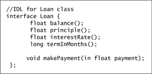
Systems communicate in many different ways. A popular method is byte streams through communication protocols such as TCP/IP and CORBA (Figure 4-4). Documenting services requested or provided may be as simple as documenting the byte streams (position of bytes in the communication stream) or CORBA IDL.2 On the other hand, the document can also be extremely complex, and include state information, handshaking, “keep-alives,” and more. Some amazingly complex system interface documentation can be found in the telecommunications industry, where it is common to find the equipment of multiple vendors communicate routinely.
Figure 4-4. CORBA IDL definition of an applicant
Defining a Software Architecture
Defining software architecture is very important in the early stages of software development as the architecture specifies what is and what is not possible with the system. To understand this impact, ask yourself how many times you have heard it said, “To add that new feature, we are going to have to redesign the whole system.”
What is system architecture? There is no single industry standard definition of this concept, but many definitions are similar to the following:
The software architecture of a program or computing system is the structure or structures of the system, which comprise software components, the externally visible properties of those components, and the relationships among them. [Bass 1998]
Software architecture has roots in building architecture (hence the name) [Coplien 1999]; there are many similarities. Both are crafts, although the craftsmen are becoming increasingly more formal. Both are influenced by their environments and driven by their requirements. They are not so much about technology, although technological capability plays a big role in what can and cannot be done, as they are about the architects and the builders who take advantage of technology.
To develop a software architecture requires identification and prioritization of the important use cases. “Important” use cases are those in which the users derive the most benefit. In a video store use case model, “Rent video” is an important use case. “Withdraw cash” is an important use case in an ATM example. Important use cases may be significant for other reasons, such as real-time constraints, reliability, and other system qualities.
To build software architecture, you need the smallest set of use cases necessary to cover the important architectural aspects of the software system. To choose the cases, ask yourself whether each use case is going to have a significant impact on the way you structure your software. If so, is the impact already addressed by a use case in the set? Is another use case in the model more representative of the impact?
Another area to consider is the future requirements of the system. What future changes are likely to have an architectural impact on the system? Will portability—that is, the ability to change from one platform or operating system to another—be necessary in a future release? We should already understand many of these requirements as a result of building our vision document. If these requirements are functional in nature, we can create change cases (discussed in Chapter 18) or use cases to reflect these changes for consideration in our architecture. Don’t discount the future. Planning for change may be as important to creating a robust architecture as any of our current requirements.
Once you have created the set of important use cases, you can plan and describe the system architecture. Important use cases can be given a priority of 1 and become the focus of an iteration (see iterative development, Chapter 19) of the software development process, where a system limited to the architecturally relevant functionality in the identified use cases will be created. This tends to take more time than most are willing to spend at this stage.
Alternatively, an architectural prototype may be created that considers prioritized use cases but does not build production code. The purpose of an architectural prototype is to validate the architecture with the minimum amount of functionality. Considerations in an architectural prototype may be performance, scalability, ability to distribute the system, and reliability. The goals of an architectural prototype should be clearly outlined, as this form of architectural development can overlook details that would be found in actually building the system.
Once the architecture is complete, a description of the architecture should be captured in a software architecture document. This document describes the technologies and patterns [Gamma 1994] used to realize the use cases. To achieve the qualities necessary to implement this set of use cases, as well as achieving cost effectiveness and adhering to a schedule, decisions may have to be made that constrain other qualities. These decisions should be documented as well.
Another part of the software architecture definition is subsystem decomposition. In subsystem decomposition, the system is partitioned into logical subsystems. Each subsystem contains semantically similar entities. A subsystem is a subclass (in UML) of Package that represents “an independent part of the entire system being modeled” [Booch 1999]. Subsystems may be dependent on other subsystems and overlapped to form layered architectures.
For example, a subsystem decomposition of a video store example may include the subsystems “rental” and “membership” (and many more). Use cases for membership activities such as “Create new membership” would fall into the “membership” subsystem. Use cases such as “Rent Video” may be part of the “rental” subsystem. However, “Rent video” requires membership services, so there is a dependency between the “rental” and “membership” subsystems.
Not all subsystems are as concrete as the ones in the two examples. Use case assortment may create new subsystems to capture common, abstract behavior between use cases [Miller 1999]. Use case assortment develops use cases to serve as requirements for framework development. These new use cases may abstract behavior across subsystems to form new behaviors. Use case assortment is discussed in [Miller 1999].
Subsystems impose organization on the development team. Responsibilities are created as subsystems are identified. A software development team is often dedicated to a subsystem, creating team dynamics. Some subsystems, however, may be bought rather than developed. Integration will need to occur between the built and the bought pieces. Therefore, all subsystems should be documented.
Software architecture tends to be a living thing. It is enhanced over time as new system requirements are generated by new and changing use cases. Good software architecture is malleable and resistant to breakage as the changes occur.
Packaging the Architecture
Domain analysis, interface specification, and subsystem decomposition, as parts of software architecture [Jacobson 1999], can be combined into a single document or broken out into separate documents (as is described in Chapter 19). The value of separate documents is that they can address different purposes and potentially different stakeholders. Essentially, these documents represent different points of view (see Chapter 3). In some cases, the same people need all the information. In these cases, a single software architecture document is more useful.
Deciding whether to build a single software architecture document or a separate software architecture document, a system glossary, and various interface specifications should be part of the development case. The development case should explain who the stakeholders are for each document and what they intend to achieve.3 This is one of the many reasons why a single, one-size-fits-all process is not possible.
Conclusion
The use case model must be balanced with software architecture. An unbalanced use case model can result in
• A functional model (which is fine for structured or functional programming approaches)
• A disjoint or noncohesive use case model because of differing vocabularies and understandings of the system
• A fuzzy system boundary (this can also result in nonexistent or poor system scoping, see Chapter 11)
Domain analysis serves to create the vocabulary of the use case (and later subsequent object models) and help define the system boundary. Interface specifications also define system boundaries. Architecture definition serves to document the technology and patterns to used in the system development as well as ensure certain performance, availability, and quality aspects.