Lesson 11. Taking Apart an iMac (24-inch)
Reference Files
iMac (24-inch) Service Source manual (imac_24in.pdf)
iMac (Late 2006) - Technical Specifications (iMac_Late 2006_Tech_Specs.pdf)
Time
This lesson takes approximately 30 minutes to complete.
Goals
Become familiar with the removal of an LCD panel from an iMac (24-inch)
Identify general system components
In the previous lesson, you learned how to install memory in an iMac (24-inch). Now we will dig even deeper into the iMac to remove a liquid crystal display (LCD) panel. This panel, including backlights and inverter, are responsible for displaying the video signal coming from the system.
Note
The iMac (24-inch) Service Source manual refers to the monitor as an LCD Display Panel. For the purposes of this book, however, we will simply refer to it as an LCD or LCD panel.
On this book’s companion website (www.peachpit.com/ats.deskport3) you will find a complete service manual for this system, including reassembly instructions. Use the Apple Service Source manual as your guide and this text to accompany it.
If you are not an AppleCare Desktop Technician (ACDT) with an up-to-date certification, do not attempt this Take Apart procedure, as it may void the warranty on the system. This lesson and the service manual on the companion website will demonstrate the Take Apart procedure for you.
If you are currently certified as an ACDT and have access to an iMac (24-inch) for this lesson, become familiar with the Take Apart procedure until you are confident in your skills and can perform the procedure efficiently. If you are performing this procedure as an authorized repair, be sure to follow electrostatic discharge (ESD) procedures as required, and return the components to Apple in the packaging provided, taking into account any instructions that accompany the service part.
For this scenario, your lead technician has diagnosed the video issue to the LCD panel.
Required Tools and Equipment
You will need a wrist strap and a grounded ESD-safe workstation and mat. Follow the ESD guidelines discussed in Lesson 4, “Safe Working Procedures and General Maintenance.”
In addition, you will need the following tools and equipment:
• Soft, clean towel or cloth (to protect the display and removed parts from scratches)
• Nylon probe tool (also referred to as a Black Stick; may also use another nonconductive nylon or plastic flat-blade tool)
• Phillips #2 screwdriver
• Torx T6 screwdriver (magnetized)
• Torx T8 screwdriver (magnetized)
• Torx T10 screwdriver (magnetized)
• Screw tray
• Apple Hardware Test (AHT) diagnostic disc for the iMac (24-inch) model
Taking Apart the iMac (24-inch)
At each stage of the Take Apart procedure, we’ll let you know if there are special notes and information; otherwise, we’ll proceed component to component, from the outside in.
Service Manual
Open the service manual for this unit, which you will find on the companion website for this book, www.peachpit.com/ats.deskport3.
The manual is roughly divided into four sections: Take Apart, Additional Procedures, Troubleshooting, and Views. Become familiar with these different sections and the types of information they contain. We will be using the Take Apart section throughout this lesson.
The Take Apart section contains general information and Take Apart procedures to help you replace each part in the unit. The General Information pages contain important safety information, as well as other useful information to ensure the repair is performed properly and using the correct tools.
Pay particular attention to the precautions, as they may be different for each model and may have been updated since the last time you read them. This model, for example, contains the following warning in the General Information section: “When the computer is under power, be aware that the power supply contains high voltages that pose a potential hazard to your personal safety. Never work on or near the power supply with the unit powered on; and as a further precaution, always make sure the unit is unplugged when working on it with the front bezel removed.”
In the service manual, go to page 51, where Take Apart material on the LCD panel begins. Notice that this procedure begins by listing the tools required, as well as any preliminary steps required, and the part location.
After ensuring that you have the correct tools, proceed to the section that covers the first preliminary step: the access door. As with the LCD panel section, the Access Door section lists required tools, preliminary steps, and part location.
As covered in Lesson 4, in addition to following the safety precautions for this unit, don’t wear jewelry, watches, necklaces, or other metallic articles that could present a risk if they accidentally make contact with the power supply circuitry. Although you won’t be working on a powered-on unit during this lesson, make it a rule to take off any jewelry before doing technical work.
For this lesson we will assume that you have followed these steps:
- Read the General Information section, which contains the safety precautions.
- Set up a grounded ESD workstation and mat, and put on your ESD wrist strap.
- Unplug the unit from the wall outlet and the computer itself.
- Properly ground yourself.
For most steps, the unit should be placed screen-side up, with the bottom facing toward you. Now we can review the procedures themselves in detail.
Access Door
Begin by reading the steps outlined in the procedure, reviewing all pictures, precautions, and notes. You should be somewhat familiar with this procedure from Lesson 10, “Upgrading an iMac,” during the memory upgrade procedures for this unit.
This procedure begins with a preliminary step: Place the computer face down so that the bottom is facing you. To remove the access door, raise the stand and loosen the two captive access door screws.
Now you can remove the door, revealing the memory compartment. You do not need to remove the memory modules for this procedure, and the dual inline memory module (SO-DIMM) levers must remain closed, as you will see later in the procedure.
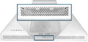
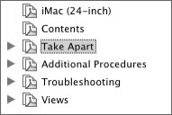
Notice the location of the serial number for this unit. The serial number should be visible on the bottom of the stand, as shown below.
Moving on to the next preliminary step, we’ll remove the front bezel.
Front Bezel
Read the procedure in full detail on page 17 of the service manual, ensuring that you have the correct tools and understand any safety precautions involved.
The first two steps position the computer for you so that you can easily locate and remove the screws.
You may encounter many types of screws during a repair. It is a best practice to use a screw tray. It will keep your screws organized in order of removal, which you replace in reverse order to reassemble the unit.
Note
The iMac (24-inch) does not require a special access card, as other models do. Eventually you will need to obtain an access card to perform procedures on other models. The design of the iMac (24-inch) incorporates the use of screws for the above step instead.
In step 3 of the service manual, you hold the memory card levers and start tilting up the lower end of the bezel. Grasp the levers delicately.
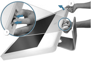
Now that the lower corners are loosened, you can lift the bezel partially to reveal the microphone and camera cables. Take particular care to avoid damaging the face of the LCD panel. Disconnect the camera cable from the camera board and the microphone cable from the cable extension.
You can now remove the front bezel from the unit and move on to the LCD panel itself.
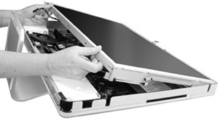
LCD Panel
You have completed the preliminary steps of removing the access door and the front bezel. Now return to the removal procedure on page 51 of the service manual.
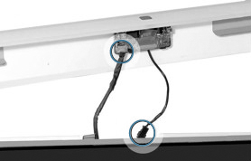
After placing the computer face up, remove the low voltage differential signaling (LVDS) connector and inverter cable in steps 2 and 3.
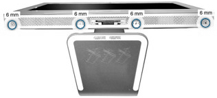
Once you have removed the eight screws from the panel frame sides in step 4, place them in the screw tray. Notice that these are 8-millimeter (mm) screws and the front bezel screws were 6 mm screws.
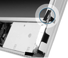
In step 5, you peel up the strip of tape at the lower corners of the LCD panel on both sides. This tape forms part of the electromagnetic interference (EMI) shield. To follow Federal Communication Commission (FCC) guidelines (as well as guidelines from many other regulating agencies worldwide), the computer’s EMI shield reduces spurious radio emissions emanating from the computer.
Later you must place the tape (pictured below) in its original position to ensure the integrity of this shielding.
Carefully grasp the LCD panel at the bottom edge and tilt up the panel to remove it from the computer assembly. Do not press on the screen panel itself in any way.
Note
If you are replacing the LCD panel as part of an authorized repair, disconnect the LVDS cable from the panel and the inverter cable from the inverter board before returning the module to Apple. Transfer the two cables to the replacement panel. A replacement panel includes the inverter board, both display panel mounting brackets, the EMI strip surrounding the panel, and the foam strip and gaskets.
When You Are Finished
If you are performing this procedure as part of an authorized repair, return the faulty LCD panel to Apple in the packaging provided, taking into account any special instructions that were enclosed in the part box. Consult the service manual for the replacement procedures.
Verify that the system works correctly by starting up the system, running AHT, and doing a few user tasks such as printing a file or viewing graphics.
Account for all of your tools and clean up your workstation if needed.
Next Steps
Each iMac model design has a unique set of Take Apart procedures, challenges, and precautions. It is important to review the latest service manual for the model you will be repairing. Once certified and working for an approved service provider, you will be able to access additional iMac service manuals. Let’s look at some differences between the models as an example.
The iMac (Flat Panel) presented a number of challenges for heat dissipation. The design incorporates the use of a heat pipe and fan to conduct heat away from the microprocessor to the metal base of the unit. The use of Thermal Pads and Thermal Grease to ensure heat conductivity between heat producing components and those that dissipate heat is crucial to the unit. This unit also requires 17 inch-pounds of torque to reattach the bottom housing. Given its unique design, special tools and a service stand are required to service this unit.
The iMac G5 has two different types of design and layout within very similar shells, and it’s important to select the correct service manual. The iMac G5 was produced with and without an optical drive initially, which meant that two different midplane boards were produced, followed by a third for the 1.8 GHz model. The different models have different inverter installations procedures and neck assembly procedures.
The Intel-based iMac models all have different layouts, and all except the iMac (24-inch) require a special access card.
Lesson Summary
• Each iMac model has different Take Apart procedures that are explained in detail in that model’s service manual. The information presented in this lesson applies to the iMac (24-inch) only.
• Gaining access to a particular component often requires the removal of other components first.
• Whenever you work on the internal components of an iMac, it’s imperative to follow proper ESD procedures.
• You must unplug the AC power cord to prevent the iMac from turning on during the Take Apart procedure.