Lesson 15. Taking Apart a Mac mini
Reference Files
Mac mini Service Source manual (mac_mini_early_late_06.pdf)
Time
This lesson takes approximately 45 minutes to complete.
Goals
Remove a logic board from a Mac mini
In Lesson 14, “Upgrading a Mac mini,” you learned how to install memory and a hard drive in a Mac mini. In this lesson, you’re going to dig deeper into the Intel-based Mac mini (Early 2006) to remove a faulty logic board—one of several possible reasons a Mac mini won’t turn on, has no startup chime, has no drive or fan sound, or has an unlit power-on LED (see Lesson 16, “Troubleshooting a Mac mini”).
Use this text along with the service manual included on this book’s companion website (www.peachpit.com/ats.deskport3) to follow step-by-step Take Apart instructions. (Apple Authorized Service Providers [AASPs] should download and refer to the latest service manual from AppleCare Service Source before servicing any Apple product.) You’ll begin by opening the service manual to the General Information pages in the Take Apart section.
At each stage of the Take Apart procedure, we’ll let you know about special notes and information; otherwise, we proceed component to component, from the outside in. Several of the steps required for removing the logic board are the same for upgrading the Mac mini and were covered in detail in Lesson 14.
Note
The Mac mini is not designed with any Do-It-Yourself (DIY) parts for repair by users. If anyone other than an AASP opens a Mac mini for any reason, and any damage to the unit results, the repair of such damage will not be covered under the Apple warranty or the AppleCare Protection Plan.
Required Tools and Equipment
In addition to the standard electrostatic discharge (ESD) wrist strap and mat—which you should always use, following the guidelines discussed in Lesson 4, “Safe Working Procedures and General Maintenance”—you will need the following tools and equipment:
• Soft cloth
• Torx T10 screwdriver
• Tweezers
• Nylon probe tool, also called a Black Stick (or other nonconductive nylon or plastic tool)
• Putty knife, 1.5 inch (38 mm), flexible blade
• Phillips #0 screwdriver
• Apple Hardware Test (AHT) diagnostic disc for the Mac mini model
Preliminary Steps
Review the preliminary steps you will need to follow in order to remove a logic board. You will find these instructions on page 16 of the service manual.
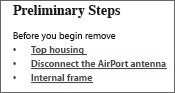
Top Housing
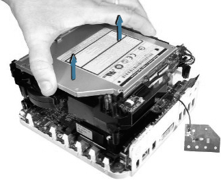
The first step in replacing any internal component is to remove the top housing of the computer.
- Perform preliminary steps 1 through 5 on page 16 of the service manual.
For the protection of you and the computer, always remember the following:
• Shut off the computer and unplug it from its power source before attempting to open the unit.
• Follow ESD procedures at all times.
- Perform removal procedures 1 through 7, beginning on page 17 of the service manual.
Use caution when using the putty knife. Be extremely careful not to scratch or dent the top or bottom housing when inserting the tool. If you insert the tool too deep, it could damage the EMI foam on the inside of the top housing.
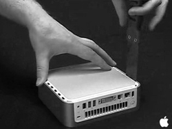
- Set aside the top housing. As always, make sure that your work area is clean and that the top housing is protected from being scratched.
AirPort Antenna
Proceed to page 23 of the service manual to disconnect the AirPort antenna.
- On the internal frame, locate the spring and black plastic posts to which the AirPort antenna is attached. With your fingers, squeeze the black posts to release the AirPort antenna.
- Pay particular attention to avoid bending the antenna.
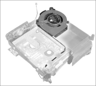
Internal Frame
Gaining access to the logic board requires first removing the black plastic internal frame, to which various other components are attached.
- Perform removal procedure steps 1 through 5 on page 29 of the service manual.
- After you have removed the internal frame from the bottom housing, take a moment to examine several parts that are connected to the internal frame.
The Bluetooth antenna is paired with the AirPort antenna, and vice versa. Should you need to replace either in the future, keep in mind that you will need to replace both. Do not mix different vendors’ antennas; they may interfere with each other.
When taking apart a Mac mini, note how cables are routed before removing any parts. When you reassemble the system, place the cables in the same positions they were in before Take Apart. There is very little room to spare inside of these systems, and cables can be damaged unless they are replaced exactly to specifications.
Keep in mind that the Mac mini has a large number of components packed very tightly into a small space. It’s important that the Mac mini is placed on a hard, flat surface when running to maximize airflow into the base of the computer. Also, keep other materials and equipment away from the Mac mini.
Be sure the fan connector is connected during reassembly. If it is disconnected when you turn on the computer, the Mac mini will quickly flash the LED and then shut off to protect itself from thermal damage.
Now that the top housing is put aside, the AirPort antenna is disconnected, and the internal frame is removed, you can remove the logic board.
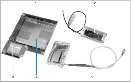
1 Mezzanine board
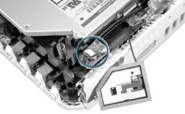
Fan (Highlighted grey object at top corner)
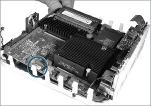
SMC reset switch (circled in blue)
Logic Board
The logic board contains the microprocessor and SMC, and it manages both the hard drive sensor and fan. First, review the steps in the service manual beginning on page 106:
- Perform step 1 of the removal procedure to disconnect the power button cable.
- Perform step 2 on page 107, where you will disconnect both the hard drive sensor and the power-on LED.
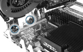
Hard drive sensor (right blue circle)
Power-on LED (left blue circle)
- Perform step 3 on page 108 to remove the standoff screw. The standoff screw will require the use of a Torx T10 screwdriver. As you remove the standoff, use as little pressure as necessary, and keep a steady hand. When you replace the standoff screw later, do not over tighten or strip it. As your skills grow as a technician, you will develop a light touch when working with small parts.
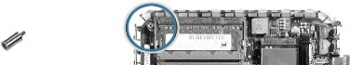
Standoff (circled in blue)
- Perform step 4 on page 108 to lift the logic board. As you are lifting it, do not force the logic board by bending it. If you feel that the logic board is still tightly attached, do not force it; review all of the proceeding steps to ensure that you did not skip any.
Note
The logic board contains thousands of metal traces that carry signals to all of its components. Stressing these traces can cause damage.
- Perform steps 5 and 6 on page 109 of the service manual.
When You Are Finished
- Return the faulty logic board to Apple in the packaging provided.
- Install the replacement logic board following the instructions in the service manual on page 110.
- Follow the internal frame reassembly steps in the service manual, beginning on page 32.
- Verify that the system works correctly by starting up the system, running AHT, and doing a few common user tasks, such as launching a browser, opening applications, or launching Mail.
When replacing a logic board or bottom housing, put in a new thermal pad as well. Of course, any time you find the pad is torn, withered, or damaged, replace it. The thermal pad transfers heat from the microprocessor and logic board to the bottom housing to cool the unit.
Tip
Wear gloves to ensure that the oil in your skin does not degrade the pad’s ability to conduct heat properly.
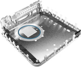
Thermal pad (circled in blue)
Lesson Summary
• There are no DIY parts in a Mac mini. If anyone other than an AASP opens a Mac mini for any reason, and any damage to the unit results, the repair of such damage will not be covered under the Apple warranty or the AppleCare Protection Plan.
• Gaining access to a particular component often requires the removal of other components first.
• Whenever you work on the internal components of a Mac mini, you must follow proper ESD procedures.
• You must unplug the AC power cord to prevent the Mac mini from turning on during the Take Apart procedure.
• When taking apart a Mac mini, you must be very sure of how cables are routed before removing any parts.
• Airflow and heat transfer are important considerations with the Mac mini.