Chapter 5. Programming the Arduino and AVR Microcontrollers

This chapter is an ambitious high-level tour of the tools, concepts, and techniques that you can use to create, compile, assemble, and load software onto an Arduino. There are many deep subjects covered here in broad strokes, and it would be impossible to do any of them real justice in the space of a single chapter. The goal is to provide you with enough information to get previous experience with microcontrollers, you may find out some things about the Arduino environment that you were not aware of before.

Note

This chapter does not describe the C or C++ languages. Those topics are covered elsewhere in great detail (refer to Appendix D for some suggested books). The intent here is to impart an understanding of how the contents of a program or a sketch are converted into binary codes that the AVR MCU, on an Arduino board or wherever it might be, can execute, and what is involved in making that happen.

This chapter starts with a short overview of cross-compiling, the technique of using a compiler and other tools on one computer system to create executable programs that can be transferred to another computer, perhaps with a completely different architecture. This is exactly what the Arduino integrated development environment is designed to do. Chapter 6 provides a more detailed look at the low-level development tools and techniques that the Arduino IDE utilizes, but here the focus is on what the Arduino IDE can do and how you can use it effectively.

Bootloaders are introduced next, with emphasis on AVR microcontrollers. The bootloader is an essential feature of the AVR family of parts used on Arduino boards, and understanding how it works can help to reduce frustration and lay the foundation for installing your own bootloader should the need arise. In Chapter 6 we will look at methods for installing a new bootloader, perhaps of your own design.

The Arduino IDE is introduced next, along with guidance on how to install the IDE on various host computers and how to configure it for your own preferences. We will also take a quick look at what is going on under the hood of the IDE, and how it evolved from earlier tools. A walk-through of a simple program illustrates the key points in the creation of an Arduino program, known as a sketch.

The chapter wraps up with an overview of the Arduino source code, and where you can get your own copy to examine. Having the source code available, both for the supplied libraries and for the IDE and its components, can help to answer questions about why something happened the way it did, and help you determine if you really want to try an alternate approach to programming an Arduino.

Note

Remember that since the main emphasis of this book is on the Arduino hardware and related modules, sensors, and components, the software shown is intended only to highlight key points, not to present complete ready-to-run examples. The full software listings for the examples and projects can be found on GitHub.

Cross-Compiling for Microcontrollers

Like for most single-board microcontroller systems, programs for an Arduino and its AVR MCU are developed on another system of some type (Windows, Linux, or Mac) and then transferred, or uploaded, to the AVR microcontroller on the Arduino board. The development system is referred to as the development host, and the Arduino or other MCU-based device is called the target. This type of development process has been around for quite a long time, and has been used whenever it was necessary to create software for a target machine that didn’t have the capability to compile code for itself.

The technique of creating software for one type of processor on a different type of system is referred to as cross-compiling, and it is really the only way to create compiled software for microcontroller targets. Small microcontrollers like the AVR (or any small 8-bit device, for that matter) simply don’t have the resources to compile and link something like a C or C++ program. A more capable machine with resources such as a fast CPU, large-capacity disk drives, and lots of memory is used to do the compiling and linking, and then the finished program is transferred to the target for execution.

In some cases the host system might even have an emulator available for the target that allows the developer to load and test programs in a simulated environment. An emulator might not provide a 100% perfect simulation of the target MCU and its actual environment, but it can still be a useful tool for checking the basic functionality of the software before it is actually uploaded to the real MCU. There are several AVR emulators available for the Linux operating system, including simavr and the GNU AVR Simulator (see Appendix E for a list of Arduino and AVR software tools, with links).

Bootloaders

Getting a program into a modern microcontroller might entail any one of several different methods, but the easiest is to let the MCU itself assist with the process. This is accomplished with a small preloaded bit of firmware called a bootloader (see the sidebar “Origins of Firmware” for a quick discussion of firmware).

The AVR family of microcontrollers provides reserved space in the on-board flash memory space for a bootloader. Once the MCU has been configured to use the bootloader, the address of this special memory space is the first place the AVR MCU will look for instructions when it is powered up (or rebooted). So long as the bootloader is not overwritten with an uploaded program, it will persist in memory between on-off power cycles.

Reserving the bootloader location typically involves enabling an internal switch, or fuse, with a special programming device that communicates with the MCU through an ICSP or JTAG interface. The MCU examines the fuse configuration (nonvolatile configuration bits) at startup to determine how the flash memory is organized and if space has been reserved for some type of bootloader or other startup code. (For more details on the fuse bits used in the AVR, refer to “Fuse Bits”).

A key feature of the AVR devices is their ability to load program code into their internal flash memory via a bootloader and a serial interface. In the case of the ATmega32U4 (described in Chapters 2 and 3), the USB interface can be used to upload the program code into the MCU; no special programming device or auxiliary MCU is necessary.

Arduino boards—both the official products and the software-compatible boards—come with an Arduino-type bootloader already loaded into the MCU. The Arduino bootloader implements a specific protocol that allows it to recognize the Arduino IDE and perform a program data transfer from the development host to the target board. The Arduino bootloader is described in detail in “Bootloader Operation”, and some techniques for replacing the bootloader with one of your own choosing are discussed in “Replacing the Bootloader”.

The Arduino IDE Environment

As of the date of this writing, the most recent version of the Arduino IDE is 1.6.4. It looks pretty much the same on each platform. Figure 5-1 shows the initial screen that appears when the IDE is launched.

aian 0501
Figure 5-1. The Arduino IDE main screen

The latest version of the IDE incorporates some fixes and updates to some of the menus, adds a command-line interface for managing boards and libraries, and resolves some code highlighting issues. Support for the new Gemma board has been added. It also supports non-Arduino (that is, unofficial) boards by allowing you to enter a URL that will allow the IDE to retrieve information about a board from the supplier’s website and integrate it into the IDE’s board manager.

If you have an older Arduino board (something like a Diecimila, Duemilanove, or Uno), then not having the latest version of the IDE really isn’t that big of an issue. Most people using an older version of the IDE with an older type of Arduino board probably won’t even notice that they don’t have the latest changes. If this applies to you, unless you plan to work with one of the newer Arduino boards (such as the Yún, Zero, or Gemma), you can probably put off getting the latest version of the IDE, at least for now.

Installing the Arduino IDE

The procedure for installing the Arduino IDE and libraries varies from extremely easy to very involved, depending on your platform and how much effort you want to put into it. For most people using Linux the easiest approach is to download an installation package via a package manager and it let it deal with also installing the necessary support packages.

The downside to this is that what is available from a package repository may not be the latest available version. The Arduino main website will always have the latest version, but gathering all the necessary bits and then getting them up and running on Linux can involve multiple manual steps. Windows and Mac OS X are easier to deal with in this regard, as discussed in the following sections.

After installation is complete, it’s a good idea to take a few minutes and look through what has been installed on your system. In the Arduino installation directory you will find the source code for numerous examples, sources and examples for the stock libraries, hex (binary loadable image) files for various versions of the bootloader, and documentation in the form of a suite of HTML pages that can be viewed with a web browser or opened using the Help menu item in the IDE.

Downloads for supported host systems are available from Arduino.cc. Just select the one that it is appropriate for you.

Windows

Installing the Arduino IDE on a Windows system is straightforward. The installation package, arduino-1.6.4-windows.exe, takes care of all the details. If you happen to have an older version of the IDE already installed it will remove it for you before installing a newer version (but it won’t remove your existing sketches). The Arduino executables and libraries are placed in Program FilesArduino. You can also find the examples here. A directory called Arduino is created in your home directory. This is where all user-created sketches and user-supplied libraries will be located.

Linux

Most Linux distributions provide the Arduino IDE in prepackaged form, be it a deb, rpm, ymp, or other package type. This is the preferred way to get the IDE and libraries quickly and correctly installed on a Linux system. As mentioned earlier, the downside to this approach is that the package maintainers for the various Linux distributions might not have the latest version from Arduino.cc available in distribution package format. For example, the latest version of Arduino available for Kubuntu is 1.0.4.

While a distribution package is the easiest way to get the Arduino IDE installed on a Linux system, the various components can also be downloaded directly from Arduino.cc and installed manually. For some distributions this might be the only option. You can read about the supported Linux distributions on the Arduino website.

Package installation on an Ubuntu-type system (Ubuntu, Kubuntu, or some other Ubuntu-derived distribution) is done using apt-get or a similar tool. OpenSuse systems use the yast tool to install the IDE package, and other systems might use rpm or some other package manager. After installation, the various examples, hardware, library files, and tools are located in /usr/share/arduino. On my Kubuntu and Xubuntu systems my sketches and custom libraries are placed in a default location in my home directory, in a subdirectory called sketchbook.

Mac OS X

The Mac OS X version of the Arduino IDE and libraries is supplied in a ZIP file with the name arduino-1.6.4-macosx.zip. According to the Arduino website it is intended for version 10.7 (Lion) or newer. After unzipping the archive, copy Arduino.app to the appropriate location on your system (the Applications folder is one possibility).

For additional information on installing the Arduino IDE on a Mac OS X system, refer to the Arduino.cc website.

Configuring the Arduino IDE

You can tailor the IDE to suit your needs by using the Preferences dialog, found under File→Preferences on the main menu (under “Arduino” on a Mac). This dialog allows you to specify the sketch directory, specify an external editor (if you don’t like the one that comes with the IDE), and modify various behaviors of the IDE. Figure 5-2 shows the Preferences dialog for an older version of the IDE on a Linux system.

The preferences file, which the dialog refers to as /home/jmh/.arduino/preferences.txt in Figure 5-2, contains many more settings that are not shown in the dialog. But, as it states, don’t edit this file while the IDE is active.

Figure 5-3 shows the Preferences dialog for version 1.6.4 of the IDE. It has many more options than the older version, but it is still just a graphical version of the preferences file.

aian 0502
Figure 5-2. Old-style IDE preferences dialog
aian 0503
Figure 5-3. New-style IDE Preferences dialog

The preferences file is an ASCII KVP (key/value pair) data file that contains settings for the editor, application initial display geometry (the size of the Arduino IDE window), serial interface parameters (baud rate, data size, etc.), and the browser to use for viewing the supplied HTML help files, among other things.

The preferences file also contains information about the last sketch that was edited, and the last size of the IDE window. Because it is dynamically modified by the IDE while it is running, it should only be manually edited when the IDE is not active.

For the older version of the IDE, this may be the only way to modify parameters such as the indent size (the default is 2 spaces, but I prefer 4), the size and type of font used in the editor (the default is Monospaced with a size of 12, but I usually set it to 11 so I see more in the editor window), and tab expansion. The newer versions of the IDE offer more options in the Preferences dialog, but there may still be a few things you might want to tweak in the preferences.txt file itself.

Cross-Compiling with the Arduino IDE

What makes an Arduino special, instead of just being yet another PCB with an AVR soldered onto it, is the Arduino IDE, the Arduino firmware, the runtime code, the software libraries developed by Ardunio.cc, and of course the programs supplied by you, the developer. The Arduino IDE is a quick and easy way to build and load software for an AVR chip. It accomplishes this by effectively hiding much of what goes on when code is compiled, linked, and transferred to an AVR target.

Note

The programming language used by the Arduino IDE is typically C++, although it can also use C, as the AVR-GCC toolchain will accept either. For this reason you will see C/C++ when this text refers to both languages, and C or C++ when discussing a particular language.

Individual source code files are displayed in the IDE in what are referred to as “tabs.” You can switch from one file to another by simply selecting the appropriate tab at the top of the editor window. When the source code is compiled the IDE will step through each tab, creating an object file for each one.

The Arduino IDE uses the avr-gcc compiler and related tools (referred to as the toolchain) to build the binary executable code for an AVR device. The libraries supplied by Arduino.cc have functions available for things like time delays, serial data output, and other capabilities (see Chapter 7).

Sometimes the term “Arduinoese” has been used to imply that the Arduino uses its own unique dialect of C/C++. This is incorrect. The language used is real C or C++, with some limitations on what can be done with C++ source code. Recall that the Arduino IDE is really nothing more than a “wrapper” around the AVR-GCC toolchain (covered in “The AVR Toolchain”).

Specifically, in avr-libc there is no support for the C++ new and delete operators, but they are provided by the Arduino team. You can find the Arduino definitions in /usr/share/arduino/hardware/arduino/cores/arduino/new.h on a Linux system, in C:Program FilesArduinohardwarearduinoavrcoresarduino on a Windows system, and in /Applications/Arduino.app/Contents/Java/hardware/arduino/avr/cores/arduino on the Mac.

In addition, C++ templates are not available, and exceptions are not supported. Classes, including constructors and destructors, are supported, however. Pure C code has few limitations. Even malloc() and free() can be used, with some cautions (see the avr-libc user manual for details and guidance). But bear in mind that using dynamic memory allocation with an embedded MCU is technically questionable and can lead to some difficult problems and clumsy code. Like the old saying goes: just because you can, doesn’t mean you should. There needs to be a very compelling reason to use dynamic memory with a memory-constrained microcontroller.

The source of confusion over the language used with the Arduino IDE may be the predefined macro definitions and functions that the Arduino environment uses to simplify access to the various I/O functions of the AVR MCU. An Arduino sketch may have an odd name and an unusual file extension (.ino), and it might look like a stripped-down version of C, but that is intentional. It makes perfect sense when you consider the original intended audience for the Arduino—namely, people who might not have any significant programming experience (or even none at all). But all the messy complexity of C and much of C++ is still there, if you want to use it. Chapter 6 describes the process of creating executable code for an Arduino (or any AVR MCU, for that matter) using the underlying AVR-GCC toolchain components, a text editor, and makefiles.

The Arduino Executable Image

Executable Arduino software (the executable image described earlier) typically consists of three primary components: the sketch created by a developer (you, perhaps), the libraries used to access the various functions of an AVR, and the runtime code that contains a main() function and a loop for the application software to execute within. If you look back at Figure 5-1, you can see that the IDE has helpfully supplied a minimal template for you to fill in with your own code.

The tools and software components involved in creating executable code for an AVR microcontroller can be divided into two primary categories: host development tools and runtime compilation sources, and the target-side executable binary code for the AVR microcontroller. Figure 5-4 shows a block diagram of the primary Arduino software components, and includes the user-supplied program (sketch) to show how things fit into a complete executable binary image.

The Arduino Software Build Process

There are five main steps in the Arduino build process when using the IDE:

Source preparation

The sketch is modified slightly by the IDE, which adds the #include statement "WProgram.h" for version 1.0 or greater of the IDE, or "Arduino.h" for older versions of the IDE. Tabs (source files) that do not have an extension are concatenated with the main sketch, creating a large single source code file (tabs with .c or .cpp extensions are compiled separately).

The IDE also attempts to create function prototypes for any functions other than setup() and loop() found in the sketch. These are placed at the top of the sketch file, immediately after any comments or preprocessor statements (#include and #define) but before any other types of statements. In a conventional C or C++ source file these would be placed in a .h header file to be included when the code is compiled, but the Arduino IDE takes care of this for you by dynamically creating and inserting them into the sketch source file. The last part of the source preparation entails appending the contents of the standard main.cxx file to the sketch (this is where main() is defined).

aian 0504
Figure 5-4. Arduino software organization
Compilation

Arduino uses the AVR-GCC compiler suite to translate the source code into binary files called object files. These are not immediately executable, but must be processed by the tool called the linker before the Arduino hardware can deal with them (refer to the next step). The AVR-GCC compiler is a form of the base GCC compiler built specifically for use with Atmel’s line of AVR devices. Due to the limitations imposed by the target hardware (memory, mainly) not all C++ capabilities are supported, but C support is complete.

The compiler accepts a large number of command-line arguments, also called switches. The Arduino IDE takes care of providing the correct switches to the compiler. These include specifying where standard include files are located, optimization options, target-specific options, and warning message levels, among other things.

Linking

Linking is the process of connecting object files and library modules. The basic idea is to fill in the “holes” in the object files where the original source code referred to a data object or function in an external library or object, but the compiler couldn’t resolve the address at the time the code was compiled. The linker’s job is to locate the missing references and write them into a final executable binary file, along with the binary code for the referenced data or functions.

Conversion

The binary file created by the linker must be converted to what is called Intel hex format, which is what the bootloader firmware on the AVR device expects. The utility avr-objcopy can be used to do this, and it is described in Chapter 6.

Uploading

The final step involves transferring the completed executable binary file to the Arduino hardware. This is accomplished using a USB link (usually) and the bootloader firmware in the microcontroller, along with a utility called AVRDUDE (it’s actually an acronym). It is also possible to load executable code into an AVR device directly via the ICSP interface (such as when there is no bootloader), and the Arduino IDE supports this.

Sketch Tabs

It is possible, and actually quite convenient, to divide a large sketch into smaller source code modules (i.e., files), each with its own include file. When the IDE loads a sketch it looks in the sketch’s directory for any additional files. Auxiliary files may have no extension, or a .c, .cpp, or .h extension. Files with a .c or .cpp extension appear in a tab but are compiled into object files to be linked with the main sketch code. Files without an extension are included into the sketch. In order to use a tab file with a .h extension, it must be referenced via an #include statement using double quotes (not angle brackets).

If your auxiliary files have their own include files they must all be included in the main sketch, even if it doesn’t reference any of the code itself. The same applies to external library modules. If an auxiliary file uses a class in a library but the main sketch does not, both it and the main sketch still need to reference the library’s include file.

A technique I like to use involves putting all the global variables (including class objects, as mentioned earlier) into a separate source file. This allows any other modules that need to access the variables to do so. It also makes the main sketch a lot easier to read, as it could end up with just the setup() and loop() functions. You can read more about multifile sketches at arduino.cc, and Chapter 11 describes a working example created for the DDS signal generator (the full source code is available on Github at https://github.com/ardnut).

Arduino Software Architecture

Regardless of how big or small it might be, a sketch always consists of at least two required functions: setup() and loop(). The setup() function is called once when the sketch starts. The loop() function executes continuously until the power is disconnected or the Arduino board is reset. loop() is called repeatedly by the main() function that is automatically supplied by the Arduino IDE. A sketch may also have additional functions. For example, the sketch for the thermostat shown in Chapter 12 has multiple functions in addition to the mandatory setup() and loop(). The main function runtime code is described in “Runtime Support: The main() Function”.

A sketch will also have statements at the start of the file that define other files to include, constants for I/O pins and other values, and global variables. You can see how a typical sketch is organized in “An Example Sketch”. The sections “Constants” and “Global Variables” discuss constants and global variables, respectively.

A never-ending main() loop, sometimes called an event loop, is a common way to program microcontrollers. A small device like an AVR doesn’t load program files from disk, and any program executing on it is designed to perform a specific function (or range of functions) continuously. So, using the concept of a run-forever primary loop makes perfect sense. Because the program code is stored in flash memory, it will be ready to run again after the Arduino is powered up or reset.

To help put things into perspective, Figure 5-5 shows how the main() function supplied by the Arduino IDE calls the setup() and loop() functions in the sketch.

In Figure 5-5, an external library class object is instantiated (i.e., initialized) outside of both setup() and loop() so it will be available to all the functions in the sketch. In addition to setup(), loop(), and any other functions in the main sketch, there can also be functions in other files, and additional files of source code included in the sketch will be handled by the Arduino IDE as tabs.

aian 0505
Figure 5-5. Arduino program structure

Note that a tab is not a true library; it’s just more sketch source code kept in a separate file. The code used in a tab could be reused in other sketches, but unlike with a real library, you need to manually specify the tab when a sketch is created—just providing an include directive in the main sketch source file is not sufficient. To add code to a sketch in the form of a tab, use Sketch→Add File from the IDE menu bar. The source file for the tab does not need to reside in the same directory as the main sketch file.

External libraries are integrated with the final executable image after the sketch code, along with any tab files, is compiled. The Arduino IDE will generate the correct linker options based on the include statements placed at the start of the sketch. See “Using Libraries in Sketches” for more on incorporating libraries into a sketch.

Runtime Support: The main() Function

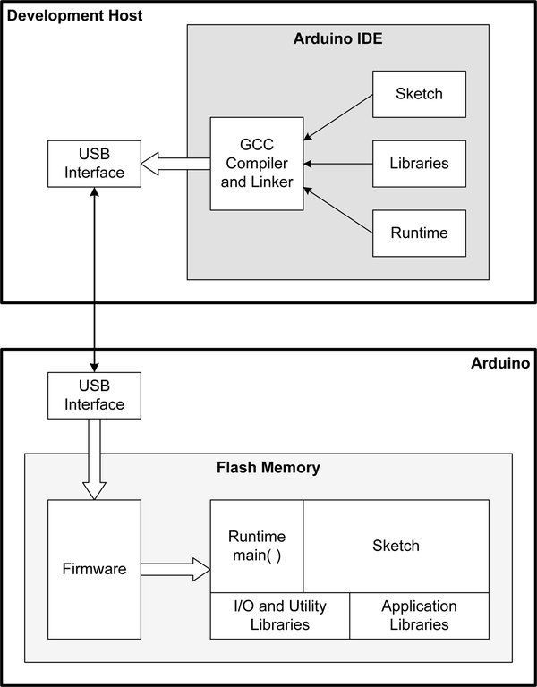
Compilers used with Linux, Windows, and Mac OS X systems provide a platform-specific library of functions called the runtime library. On a GCC-based system this is typically called libgcc.a or libgcc_s.so.1, and on Windows the runtime libraries usually go by the names MSVCRT.DLL for C and MSVCPP.DLL for C++. The AVR version is avr-libc, which is discussed in Chapter 6. The runtime library will contain commonly used functions specific to a particular platform. These can be common math operations, low-level I/O functions, system timers, support for printf(), and so on.

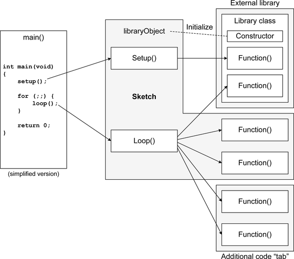
The Arduino also has its own additional runtime support module, but with a twist. By itself, a program sketch won’t do much. It has no main() function to get it started and no way to continuously execute once it does start. The Arduino runtime support includes the necessary main() function, along with other startup configuration functions. As can be seen from Example 5-4, it’s actually very simple, and is a typical design for small microcontrollers.

Example 5-4. Arduino main() function
int main(void)
{
    init();
    initVariant();

    #ifdefined(USBCON)
    USBDevice.attach();
    #endif

    setup();
    for (;;) {
        loop();
        if (serialEventRun) serialEventRun();
    }
    return 0;
}

The calls to init(), initVariant(), and (if applicable) USBDevice.attach() are determined at compile time based on the type of Arduino target hardware selected in the IDE. These comprise the primary components of the runtime support code specific to each type of Arduino board. In a larger realtime operating system (RTOS) these might be part of the board support package (BSP) supplied by the RTOS vendor or created by a developer. The functions are described here:

init()

Located in Arduino/hardware/arduino/avr/cores/arduino/wiring.c, this function initializes various AVR peripheral components such as timers, timer/counter prescaling, A/D converter prescaling, and PWM output modes according to the AVR part used with a particular Arduino board.

initVariant()

This provides a “hook” in the form of a so-called weak function declaration. Typically used to provide additional runtime initialization for hardware not covered by the definitions and code supplied with a standard Arduino development environment.

USBDevice.attach()

This refers to the attach() method of the USBDevice class found in Arduino/hardware/arduino/avr/cores/arduino/USBCore.cpp. This class provides the functionality necessary to communicate with a USB interface.

For many people, what these initialization functions actually do is irrelevant. However, if you want to really understand what the Arduino IDE does and how it does it, then reviewing the source code for these support functions is a worthwhile endeavor. Obtaining the source code is described in “Arduino Source Code”.

As described previously, the setup() and loop() functions are provided by you in the program sketch. The setup() function is typically used to define specific I/O ports and starting states, initialize some parts of the AVR peripheral functions, or perform other one-time operations. It is largely optional and can even be an empty function, but it must exist in the sketch or the linker will generate an error message.

The loop() function is where the main activity occurs in a program sketch. As can be seen from Arduino main it is called repeatedly until power to the Arduino board is removed. Interrupts can and do occur while loop() is executing, and some applications may incorporate a timer interrupt or a delay to give loop() some degree of definite periodicity (as opposed to simply free-running).

An Example Sketch

As we’ve already seen, a basic Arduino program sketch consists of two parts: the setup() function and the loop() function. Since the main() function is provided by the IDE, we don’t need to worry about it when working with simple sketches.

The simple sketch in Example 5-5 will monitor several inputs and produce an output if any of the inputs change from low to high. It could be the basis for a simple burglar alarm.

Example 5-5. Simple intrusion alarm
// CONSTANTS
// Define the digital I/O pins to use
#define LOOP1   2      // sense loop 1
#define LOOP2   3      // sense loop 2
#define ARM     6      // Arm the alarm
#define RESET   7      // Reset alarm state
#define ALERT   12     // Annunciator output
#define LED     13     // Same LED on board

#define SLEEPTM 250    // loop dwell time

#define SLOWFLASH  10  // unarmed flash divisor
#define FASTFLASH  2   // armed flash divisor

// GLOBAL VARIABLES
// State flags
bool arm_state;        // T = armed, F = unarmed
bool alarmed;          // T = in alarm state, F = all quiet
bool led_state;        // control on-board LED
bool loop1state;       // status of sense loop 1
bool loop2state;       // status of sense loop 2
bool in_alarm;         // T = alarm active, F = quiet

int led_cnt;           // flash cycle counter
int flash_rate;        // count divisor

// We will use Arduino's built-in pinMode() function to set the input or
// output behavior of the discrete digital I/O pins

void setup()
{
    // Initialize pins 2, 3, 6, and 7 as digital inputs
    pinMode(LOOP1, INPUT);
    pinMode(LOOP2, INPUT);
    pinMode(ARM, INPUT);
    pinMode(RESET, INPUT);

    // Initialize pins 12 and 13 as digital outputs
    pinMode(ALERT, OUTPUT);
    pinMode(LED, OUTPUT);

    // Initialize state flags
    arm_state  = false;
    alarmed    = false;
    led_state  = false;
    loop1state = true;
    loop2state = true;
    in_alarm   = false;

    // Set LED start condition
    led_cnt = 0;
    flash_rate = SLOWFLASH;
    digitalWrite(LED, LOW);
}


void loop()
{
    // Get arm switch value
    arm_state = digitalRead(ARM);

    // If reset is low (true), cancel alarm state
    if (!digitalRead(RESET)) {
        in_alarm = false;
    }

    // If not armed, just loop with a short pause
    if (!arm_state) {
        flash_rate =  SLOWFLASH;
        in_alarm = false;
    }
    else {
        flash_rate =  FASTFLASH;
    }

    // Check the sense loops
    loop1state = digitalRead(LOOP1);
    loop2state = digitalRead(LOOP2);

    // only go into alarm state if armed
    if (arm_state) {
        if ((loop1state) || (loop2state)) {
            in_alarm = true;
        }
    }

    if (in_alarm) {
        digitalWrite(ALERT, HIGH);
    }
    else {
        digitalWrite(ALERT, LOW);
    }

    led_cnt++;
    if (!(led_cnt % flash_rate)) {
        led_cnt = 0;              // reset flash count
        led_state = !led_state;   // invert LED state
        digitalWrite(LED, led_state);
    }

    delay(SLEEPTM);
}

Figure 5-6 shows how an Arduino might be connected to external switches for doors and windows. The reasoning behind connecting switches in series and connecting one end of the chain to ground is simple: if any of the wiring connecting the sensor switches is cut, it will trigger the alarm.

aian 0506
Figure 5-6. Simple Arduino intrusion alarm

In an application like this the sensor switches could be window frame plungers, magnetically actuated reed relays, leaf switches on sliding doors, or even a sensor module such as a sound detector. The annunciator can be anything from a 50-cent piezo buzzer to a relay to control a siren or even a phone autodialer. For more on Arduino-compatible sensors, see Chapter 9. This basic design could be extended in any number of interesting directions, all the way to creating a commercial-quality alarm system. You can find downloadable software from this book on GitHub.

Constants

There are two ways to define constants for I/O pin numbers, time delays, and other values. The first is to use #define statements. The second is to use integers that are initialized to some value and then never modified. For example, a #define statement to associate pin 2 with a name might look like this:

#define LOOP1 2  // sense loop 1

The alternative approach is to create an integer to hold the value:

int LOOP1 = 2;   // sense loop 1

If you look through example Arduino code you will see both approaches used, and both will work equally well. Although some folks may eschew the #define statement, for whatever reasons, there is a memory use trade-off to consider.

The advantage of using #define statements, as is done in Example 5-5, is that they result in a smaller compiled program size. With the #define statements the final size of the intrusion alarm program is 1,452 bytes. With the #defines replaced with int declarations, it is 1,540 bytes. That difference of 88 bytes may not seem like much, but in a large sketch with lots of I/O definitions and constants it can add up. If, for example, everything has to fit into 30,720 bytes for an ATmega328, it might make the difference between loading and failing.

Global Variables

One thing you may notice about all sketches is the use of global variables. This is common in Arduino sketches for one very good reason: the loop() function is called repeatedly by main() when the sketch code is running, and if the variables were defined in loop() they would be erased and reloaded each time that loop() was called. If loop() needs a variable with a persistent value (a counter, perhaps), then it needs to be outside of loop() so that it won’t be cleared and recreated repeatedly. Global variables also make it convenient for setup() to set initial values before loop() is first called, and any other functions in the sketch will also have access to the variables.

Global variables have gotten a bad reputation in some circles because of the problems that can arise with unintentional “coupling” between different parts of a program. In large applications that load from disk, execute, and are then terminated by a user, such as word processors, games, and web browsers, this makes sense. It’s not a good thing when one part of an application modifies a global variable and another part of the application causes a crash when it also modifies the same global variable. In systems with lots of available memory, dynamic memory allocation, semaphores and mutex locks, and the ability to pass around pointers to things like complex structures, the use of global variables might not be justifiable.

However, in the realm of embedded systems global variables are commonly used as an efficient form of shared memory that is visible to every function in the program. You can think of global variables as a panel full of switches, indicators, knobs, and dials, like in the cockpit of an airplane. Just so long as you follow the “modified by one function, read by many functions” rule things should be fine.

Since an Arduino sketch is not running in parallel with other threads or processes, the chances of an access collision are zero. Interrupts might be a challenge, depending on how they are implemented, but a little forethought can negate potential problems there, as well.

Libraries

The libraries supplied with the Arduino IDE cover a lot of things, but not everything, as can be seen in Chapter 7. Unless someone has put in the time and effort to create a library for a specific sensor or interface, then you will need to supply the code yourself. This is particularly often the case when working with custom or uncommon sensors or shields that require special functions.

With the Arduino IDE the term “library” is used in a way that might seem out of line with what you are used to if you’ve worked with GCC or Visual Studio on large projects. When building software for a full-size computer like a desktop PC, a library typically refers to a binary object archive. On Linux and Unix systems this is accomplished using the ln, ar, and ranlib tools. The resulting binary file is an indexed collection of object files (see “Objects, Images, and Source Code”) that the linker can use to fill in the gaps and generate a complete program. If it’s a dynamic library, then it will be loaded when the application is started (or even during program execution) and the linking will occur at that time.

In the Arduino IDE environment libraries usually exist as source code until they are needed in a sketch. So what is actually happening when a sketch is compiled is that the sketch (and any tab files), any necessary libraries, and the runtime code are all compiled at the same time and linked into a single binary executable image.

Using Libraries in Sketches

As mentioned earlier, when the Arduino IDE encounters an include statement that refers to a library already registered with the IDE it will generate the necessary build steps and linker options to incorporate the library automatically. However, in order for this to work the IDE must know about the library in advance.

Registering a library with the IDE is described in “Adding a Library to the Arduino IDE”. The Arduino IDE comes with a selection of libraries for common operations and I/O devices already preloaded. Figure 5-7 shows the available library listing for an older version of the IDE, and Figure 5-8 shows the library listing and library management options available in the latest version (1.6.4) of the IDE.

aian 0507
Figure 5-7. Registered library listing from older Arduino IDE

Example 5-6 shows how a library—in this case, the SoftwareSerial library—is incorporated into a sketch. The first thing to notice is the include statement at the top of the sketch file:

#include <SoftwareSerial.h>

From this the IDE will determine that it needs to locate a library with the name “SoftwareSerial,” and it will expect that library to be in its list of known library modules.

Example 5-6. Library example 1
 #include <SoftwareSerial.h>

 SoftwareSerial softSerial(2, 3);

 int analogPin = A0;    // select the input pin for the potentiometer
 int analogVal = 0;  // variable to store the value coming from the sensor

 void setup()
 {
     // set the data rate for the SoftwareSerial port
     softSerial.begin(9600);
 }

 void loop() // run over and over
 {
     // read some data from an analog input
     analogVal = analogRead(analogPin);

     // write the data to the softSerial port
     if (softSerial.available())
         softSerial.write(analogVal);

     // pause the program for 1 second (1000 milliseconds)
     delay(1000);
 }

The SoftwareSerial object is instantiated by the line:

SoftwareSerial softSerial(2, 3);

This also defines the pins to use for the serial I/O function, namely 2 and 3 (digital I/O pins).

aian 0508
Figure 5-8. Registered library listing from latest version of Arduino IDE

In the setup() function, the serial baud rate is set.

The loop() function reads a value from the A0 analog input pin, and then sends the binary value out via the softSerial object. The loop() function pauses for 1 second after each binary value is sent.

This technique can be used to send and receive binary data between two Arduino boards, but it won’t work very well if you want human-readable output. For that you will need to use the print() and println() methods in the library, as shown in Example 5-7.

Example 5-7. Library example 2
#include <SoftwareSerial.h>

SoftwareSerial softSerial(2, 3);

int analogPin = A0;    // select the input pin for the potentiometer
int analogVal = 0;  // variable to store the value coming from the sensor

void setup()
{
    // set the data rate for the SoftwareSerial port
    softSerial.begin(9600);
}

void loop()
{
    // read some data from an analog input
    analogVal = analogRead(analogPin);

    // write the data to the softSerial port
    softSerial.print(analogVal);
    softSerial.println();           // print a linefeed character

    // pause the program for 1 second (1000 milliseconds)
    delay(1000);
}

It is also possible to use the standard library printf() function to send data out over the serial port, but printf() doesn’t come preenabled with the Arduino core functions. If you want to learn how to enable printf(), and get an understanding of how it might impact your sketches, refer to the Arduino web page on enabling printf() in Arduino sketches.

You can learn more about the SoftwareSerial library module from the integrated help in the IDE in the “Libraries” section, and the source code can be found in the Arduino installation directories. SoftwareSerial is also described in Chapter 7.

Adding a Library to the Arduino IDE

User-supplied add-on libraries are the key to using external devices like humidity and temperature sensors, radio frequency (RF) modules, and infrared (IR) remote control components. You can write your own library of functions, or you can elect to install code created by someone else.

Add-on libraries are typically placed in a directory called libraries in the sketchbook directory. The set of files that comprise the add-on library reside in a subdirectory with an appropriate name. It is the name of this subdirectory that appears in the library list in the IDE. There are two ways to accomplish this:

Method 1, automatic

Recent versions of the Arduino IDE (1.0.5 and later) can automatically install library source code into your sketchbook directory for you (the actual location will depend on your operating system). From the IDE’s main menu, click Sketch→Import Library→Add Library and then select the directory or ZIP file that contains the library source code. The latest version of the IDE (1.6.4) uses a slightly different series of steps, and the library management functions are grouped under “Include Library.”

One nice thing about this method (other than its simplicity) is that the IDE will immediately recognize the new library—there is no need to restart the IDE. Also, with newer versions of the IDE you can download and install libraries from external sources.

Method 2, manual

Manually installing an add-on library for the Arduino IDE involves the following steps:

  • First, close the IDE if it is running.

  • Unzip the new library files into a temporary directory (most add-on libraries come in the form of ZIP files).

  • You should see at least two source code files, a .c or .cpp file (the program) and a .h file (an include or header file).

  • Create a subdirectory under <home>/sketchbook/libraries with the same name as the two source files.

  • Copy the entire contents of the temporary directory to the new library directory you created in the previous step.

    When the IDE is restarted you should see the library listed in the Sketch→Include Library drop-down list.

The convention for organizing the contents of an add-on library is as follows:

  IRTracker/IRTracker.cpp
           /IRTracker.h
           /keywords.txt
           /README
           /utility/IRCal.cpp
                   /IRCal.h
                   /IREncode.cpp
                   /IREncode.h
                   /IRDecode.cpp
                   /IRDecode.h
           /Examples/ScanIR/ScanIR.ino
                    /SendStop/SendStop.ino

Note that this is an example only. So far as I know, there is no IR tracker library available for the Arduino (yet).

The library subdirectory must have the same name as the source files, and this convention is used throughout the Arduino IDE’s directories. For example, in the Arduino examples directory (/usr/share/arduino/examples in a Linux system) the subdirectories have the same names as the .ino files.

As you can see in the example directory structure, there can be additional subdirectories for utility functions, and even more source files than the two files that share the same name as the subdirectory. They won’t appear in the libraries list, but the library code will be able to access them when it is compiled.

You might notice a file called keywords.txt at the base level of the library directory structure. This is an important file, as it gives the IDE some definitions regarding what things do in the library source code. The keywords.txt file for the hypothetical IR tracker library used for our directory structure example might look like this:

  # IR Tracker
  ##################################
  MAXPWR    LITERAL1
  MAXTIME   LITERAL1

  LastCal   KEYWORD1
  TotHours  KEYWORD1

  IRState   KEYWORD2
  IRSense   KEYWORD2

The format is very simple. The # (pound or hash) indicates that everything to the end of the line is a comment and should be ignored. Special keywords, listed in Table 5-1, are used to indicate the type of literal constants, classes, structures, variables, or functions to the IDE.

Table 5-1. Keyword definitions for keywords.txt
Type Definition

LITERAL1

Literal constants (i.e., macros)

LITERAL2

Literal constants (i.e., macros)

KEYWORD1

Classes, data types, and C++ keywords

KEYWORD2

Methods and functions

KEYWORD3

Structures

You can also find more information in the keywords.txt file located in the directory where the Arduino runtime components are installed on your system. On my Linux machine this is /usr/share/arduino/lib, and on Windows it can be found at C:Program FilesArduinolib. You can also look at what others have done by examining the keywords.txt files in the library subdirectories supplied with the IDE.

While it is possible to place add-on libraries in the Arduino IDE’s predefined set of directories, this is not the recommended approach. The predefined libraries supplied with the IDE are subject to change when the IDE is upgraded to a newer version. The user-contributed libraries and sketches are never altered by an upgrade.

In any case, a library component consists of two basic parts: the source module (name.c or name.cpp) and the include file (name.h). The code in the source module is a set of functions that comprise a simple C++ class. The class itself is defined in the header file. To use the library one need only copy it into the appropriate directory, start the Arduino IDE, and then select the new library from the Sketch→Import Library list. The IDE will examine the header file and place the statement #include <name.h> into the sketch.

Creating Custom Libraries

Creating a custom library for use with the Arduino IDE is straightforward. That doesn’t necessarily mean it’s simple, as libraries can be very complex, but simple or complicated, they all follow the same basic template. The source code is written in the AVR’s restricted version of C++ as a class, perhaps with one or more associated classes to help out. Look at the source code for some of the libraries listed in Chapter 7 to get an idea of how library source code is organized.

As earlier noted, a minimal library is a set of at least two files: a .cpp source file and a .h include file. The source file contains the implementation of the library class, and the include file contains the class definition, type definitions, and macro definitions.

Recall from our earlier sample directory structure that the directory containing the source and include files for the library will have the same name as the primary source (.cpp) file. It should also contain the keywords.txt and README files, and an examples directory is always a nice touch (particularly if you intend to release your library for others to use).

Arduino Source Code

The full Arduino source code set contains source files for both AVR-based boards and the ARM-based Due board, which isn’t covered in this book. The source code is available from GitHub using the URL and the git clone command. You can also download a ZIP file with an image of all the repository files from GitHub.

If you plan to delve deeper into Arduino than just the IDE, then it is helpful to have the source code on hand. Looking at the source files can help to make things much clearer. A tool such as Doxygen can be used to create a linked set of web pages with dependency graphs, call graphs, and an index of classes, source files, and functions. Although the Arduino source doesn’t have much in the way of Doxygen-specific tags, it is still possible to generate useful documentation.

At the top level, the Arduino source directory structure contains directories for application source code (app), build modules (build), hardware-specific files (hardware), and the library modules included with a standard Arduino distribution (libraries). From a low-level perspective, the hardware and libraries directories are the most interesting.

In the hardware subdirectory you can find the source code for various bootloaders, the runtime support code (which is called “core” in this source file set) that includes main.cpp, and a small collection of modules for EEPROM, serial I/O, SPI, and two-wire interfaces (in the hardware/avr/arduino/libraries directory, which is different from the libraries directory mentioned earlier). The support libraries that come with the Arduino IDE are located in the libraries directory. The subdirectories here include source code for audio, Ethernet, liquid crystal displays, SD memory cards, servo motors, stepper motors, TFT displays, and WiFi modules. There are libraries for the Arduino Robot, Esplora, and Yún products as well. Many of the library subdirectories also contain example program sketches, and some have documentation in the form of a text file.

One thing to bear in mind when reading through the Arduino source code is that it makes heavy use of #if, #ifdef, #ifndef, and #define statements to determine what will be included and compiled for a specific type of Arduino board. This can be confusing at first, and it might take a little effort to work through what is going on. It is also worth noting that in some cases a function or set of functions is used, while in other cases a class is defined for a specific purpose.

..................Content has been hidden....................

You can't read the all page of ebook, please click here login for view all page.
Reset
3.147.77.208