
Chapter 8. Shields
An Arduino shield is an add-on circuit board designed to work with the connectors on a standard Arduino board like an Uno, Duemilanove, Leonardo, or Mega. A shield has pins that interface with the Arduino so that things like DC power, digital I/O, analog I/O, and so on are available to the shield. This chapter covers some of the Arduino-compatible shields that are available, and Chapter 10 describes the process of creating a custom shield.
Shields are available for a variety of applications, ranging from minimal boards for prototyping to motor controllers, Ethernet interfaces, SD flash memory, and displays. Many shields have the ability to be stacked, allowing a base Arduino board to interface with two or more shields at once.
Note
This chapter references many different vendors and manufacturers, but it is not intended to be a specific endorsement of any of them. The shields shown here are representative of what is available, and for any given shield type you can likely find different vendors selling the same, or an equivalent, product. Shop around.
This chapter is by no means a complete list of all the various types of shields that are available. There is a quiet cottage industry that specializes in creating new variations on existing shields and new shields that have never been seen before. The selection of shields described here is broadly representative of what is available, and links are provided if you want to learn more, or perhaps buy a shield or two. In some cases I’ve included more detailed information to supplement what the vendor provides (or doesn’t, in some cases), but that doesn’t mean I’m especially fond of any particular shield. I’m just fond of documentation, so I can get the information I need to move on to what I want to do. You may also find yourself in a position of having a really useful-looking shield for which there’s little or no documentation, or where what there is happens to be in Chinese (or some other language you might not know). Hopefully this chapter will help to fill some of the gaps, or at least give you some ideas on where to look.
Tip
Some of the shields shown here are no longer available from the original vendor, but can be purchased from other sources. Most vendors provide active links to documentation, so if you find a look-alike shield (the hardware is open source, after all) you can often still get the technical information you need.
One thing to remember when looking for a shield is that some people seem to be unclear on what a shield is. It is not a module with a row of pins down one side (these are discussed in Chapter 9). A shield is a board that meets the physical characteristics described in “Physical Characteristics of Shields”. Anything else can be considered to be a module, and modules may or may not plug into an Arduino directly (they usually don’t simply plug in, but need wiring of some sort to route power and signals to the appropriate pins on an Arduino board).
Electrical Characteristics of Shields
If you compare the pinout diagrams of the various shields in this chapter, you may notice a pattern emerging: shields that employ a two-wire interface (the TWI or I2C interface) always use pins A4 and A5 of the Arduino. On a baseline-type board (Diecimila, Duemilanove, and Uno R2 or SMD) these will be found on the analog I/O connector, and on the newer extended layout boards (Uno R3, Ethernet, Leonardo) the signals also appear on the extended pin header (in the upper corner by the USB or RJ45 connector). A shield that uses I2C can utilize either set of pins, and you can assume that A4 and A5 will not be available for other uses without some clever programming.
By the same token, shields that use the SPI interface will typically use the D10, D11, D12, and D13 pins (SS, MOSI, MISO, and SCK, respectively). The use of D10 as the select is optional, and some shields use a different digital pin for that purpose. Remember that with SPI each “slave” device must be explicitly selected with a select signal before it will accept incoming data from the master device. Shields with more than one attached SPI device may also use more than one digital I/O pin as a select signal.
Shields that use the UART (or USART, as Atmel calls it) will typically use pins D0 and D1 (Rx and Tx, respectively, or RxD0 and TxD0 on a Mega-type Arduino). Some Bluetooth shields use the UART interface to communicate with a Bluetooth module, as do RS-232 and RS-485 interface shields.
Then there are shields that use almost every single Arduino pin. The DIY Multi-function shield described in “Miscellaneous Shields” is like this, but it does have pins to connect to the signals that are not specifically used on the board (three digital and one analog, in this case). In general, you can safely assume that I/O extension shields will use most or all of the available Arduino pins, and shields that support something like a display will generally not have any connection points for accessing unused signals. For this reason these types of shields are usually nonstacking, and should be placed at the top of a stack of shields on an Arduino.
Most shields do not have extremely complicated circuits but are relatively simple things based on existing ICs or components of some type. Like the Arduino boards, they are essentially carriers for various types of ICs, relays, and so on. The electrical characteristics of a shield are those of the chip or components it is designed around. This simplicity is what helps to keep the cost of a shield low, and the capabilities of the ICs or components it uses are what make a shield useful.
Lastly, some shields may buffer the signals to and from an Arduino, using active circuits or devices such as optical isolators or relays, but most of them simply serve as places to mount connectors or components, such as the extension shields shown in “I/O Extension Shields” that utilize multipin connectors. The connections, be they sockets or pin headers, are just extensions of the Arduino’s own pins, and there is nothing to protect against connecting 12 volts to a 5V (or even 3.3V) digital input and converting the AVR microcontroller on an Arduino into charcoal. Always observe the voltage and current limitations of the AVR microcontroller.
Physical Characteristics of Shields
Physically a typical shield is as wide as a baseline Arduino board (see Chapter 4 for dimensions), and it can be the same length as an Arduino, or it might be longer or shorter. It is possible to make a shield that is wider than a baseline Arduino board, as the only real constraint is that the pins on the shield line up with the pin sockets on the underlying Arduino board (see Chapter 4 for locations and dimensions). Installing a shield is just a matter of connecting the shield as shown in Figure 8-1.
Newer Arduino boards that use the R3 pin layout will have two pin sockets at the end of each row that are not used by the shield. This is unimportant, as these extra sockets are either duplicates of existing pins or not connected. In the case of the Mega boards the shield will mount as shown in Figure 4-20 in Chapter 4, with most of the pins on the Mega board not connected to the shield, and some others made inaccessible by the overlying shield PCB. All of the baseline pins and signals are available to the shield.
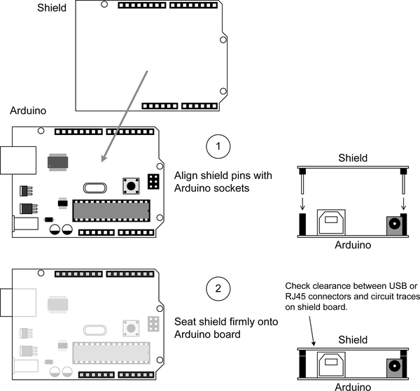
Figure 8-1. Shield mounting on host Arduino board
Tip
Always check the clearance between components on the base Arduino board and the shield PCB. In some cases a USB connector or an RJ45 jack can interfere with the shield and potentially cause a short circuit.
Sometimes you might have a problem with parts on the Arduino board colliding with the circuit traces or pads on the underside of a shield board. A small piece of electrical tape or even some heavy card stock paper can be used as an insulating shim, but the better way to deal with this is to use spacers or standoffs to physically separate the two boards. These can be short metal or nylon tubes (7/16 to 1/2 inch, or about 11 to 12 mm in length) with a center hole sufficient for a machine screw (which would typically be a 2-56 SAE type, or a suitable metric size). The difference between a standoff and a spacer is simple: standoffs have internal threads, spacers do not. A spacer or standoff serves to raise the upper board enough to prevent shorts, as shown in Figure 9-3 in Chapter 9. It also results in firm mechanical coupling between two or more boards.
When stacking two or more shields on an Arduino you can elect to use long machine screws with spacers, or you might want to consider a type of standoff that has a threaded screw-like projection at one end and a threaded hole at the other end. Also known as “jack screws,” these are common in PCs, and if you’ve ever assembled your own computer from scratch you’ve already encountered them. Figure 8-2 shows some examples of the types of spacers and standoffs that are available. These parts can be made from nylon, aluminum, stainless steel, brass, and plastic.
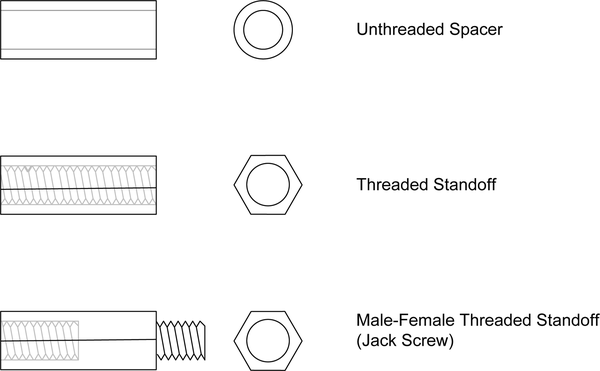
Figure 8-2. Spacers and standoff types
Spacers can also be made from strips cut from a prototyping PCB and slipped over the pins of the upper board. This technique won’t do much for physically coupling the boards, but it will add enough space to prevent collisions.
You can purchase spacers and standoffs from various sources, including Amazon, McMaster-Carr, Mouser, and Digi-Key. If you happen to have a fabrication hardware supplier in your city, you can also purchase these and other useful things (like 1-72 or 2-56 machine screws and nuts) locally.
Stacking Shields
Sometimes it doesn’t make sense to use extended-lead pin sockets to make a shield fit into a stack. If, for example, a shield has a large number of connectors that require vertical access, then there simply may not be enough room for another shield to mount on top of it. But you will sometimes encounter a shield that could stack but doesn’t have the correct connector types.
One of two techniques is used to allow a shield to be stacked on another shield: extended socket pins or offset pins and sockets. The extended pin approach allows the stacked shield to stay in vertical alignment. The offset pin and socket design results in stacked shields that are shifted over by the amount of offset between rows of pins and sockets. If the shields all shift the same way, the result can look like stairs, and the holes in the boards for mounting screws will not line up correctly.
The use of extended pins requires pin sockets with long pins for mounting on a PCB. The protruding pins on the back, or solder, side of the shield board will plug into the pin sockets on an Arduino, and another shield can be mounted on the top of the stackable shield. The offset technique uses separate pin strips to connect the shield to the Arduino and separate socket strips to accept another shield. These are mounted side-by-side, usually as closely as possible to minimize the offset between shields.
Common Arduino Shields
This section reviews some of the readily available shields. This is by no means a comprehensive list, as new shields appear continually, and older shields are discontinued or may otherwise no longer be available. In this age of rapid prototyping, fast-turnaround production, and low-cost manufacturing, a shield may appear and then vanish a few months later. To stay abreast of what is available, you might want to check out the many Chinese vendors on eBay, and the listings on Amazon.com, Adafruit, SparkFun, SainSmart, and other websites. See Appendix C for known sources of Arduino shields. Table 8-2 at the end of this chapter lists the vendors and manufacturers covered here.
The following list provides a quick reference of the shields discussed here, broken down by category:
-
-
I/O extension shields
-
I/O expansion shields
-
Relay shields
-
Signal routing shields
-
-
-
SD and microSD card flash memory
-
-
-
Serial I/O
-
MIDI
-
Ethernet
-
Bluetooth
-
USB
-
ZigBee
-
CAN
-
-
-
DC and stepper motor control
-
PWM and servo control
-
-
-
LED arrays
-
7-Segment LED displays
-
LCD displays
-
Color TFT displays
-
-
-
Data logging
-
Logic analyzer
-
24-bit ADC
-
12-bit DAC
-
-
-
Nano adapters
-
Terminal block adapters
-
-
-
Terminal block/prototyping
-
Multifunction shield
-
In this section we will also take a quick look at some uncommon shields designed for specific applications: a CNC engraver control interface, a RepRap control interface, and an FPGA game controller.
Input/Output
Input/output (I/O) shields are available that bring out the various I/O pins of the Arduino to connectors that are more robust than the pins on the Arduino circuit board (or, in the case of the Arduino Nano, the pins below the board are connected to terminal block–type connectors on a carrier for the Nano PCB).
I/O shields can be broadly classified as either extension shields or expansion shields, although the term “expansion shield” is often applied to both types. An extension shield brings out the I/O pins from an Arduino without altering the signals—it just uses different types of connectors. A true expansion shield, on the other hand, employs active electronics to increase the number of discrete digital I/O channels. These types of shields use either SPI or I2C to communicate with the host Arduino board.
I/O Extension Shields
This category of shield is used to route the input/output signals from the AVR chip to connectors that are more robust than the pin sockets used on an Arduino board. Some I/O extension shields may offer active buffering of some type, but most simply bring out the signals from the Arduino board. These are sometimes referred to as expansion shields, but that is not really correct. They simply transfer the existing signals from one connector on the Arduino to another on the shield.
- SainSmart Sensor Shield
-
This is a stackable shield (note the offset pin and socket strips in Figure 8-3). The AVR I/O is brought out as latching multipin sockets, pin header blocks, and positions for two 10-pin headers suitable for use with ribbon cable IDC-type connectors. A reset switch is also provided. This shield can be used with any Arduino board with the baseline pin configuration, including the Mega boards.
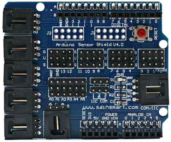
Figure 8-3. SainSmart I/O expansion (sensor interface) shield
Figure 8-4 explains the large modular connectors along the edges of the shield PCB. These are multipin connectors, sometimes referred to as “buckled” connectors, that mate with corresponding three- and four-pin plugs. The multiconductor cables are common and can be obtained from multiple vendors. One source (other than SainSmart) is TrossenRobotics.
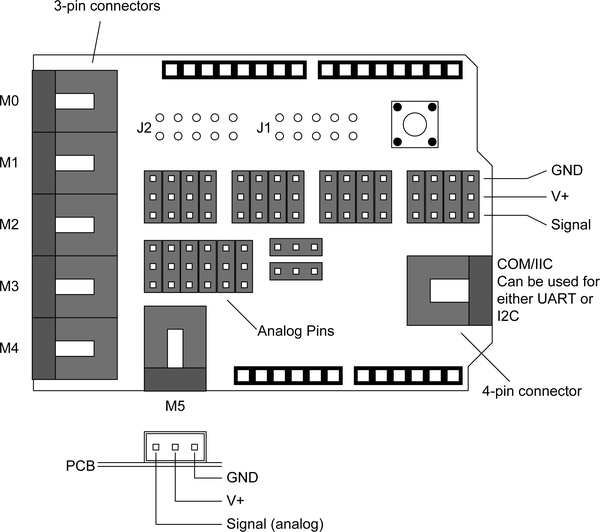
Figure 8-4. SainSmart I/O expansion shield pin and connector layout
- TinkerKit Sensor Shield
-
This stackable shield (Figure 8-5) uses long-lead pin sockets, 12 three-pin connectors, and 2 four-pin connectors. A reset switch is located between the four-pin connectors.
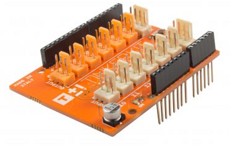
Figure 8-5. TinkerKit I/O expansion shield
The TinkerKit sensor shield was originally designed to work with the various sensor and motor modules produced by TinkerKit, but it can be used like any other I/O extension shield. Figure 8-6 shows the layout of the connectors on the PCB. These employ a three-wire scheme like that used with the SainSmart board shown previously. For more about the TinkerKit modules designed for use with this shield, refer to Chapter 9.
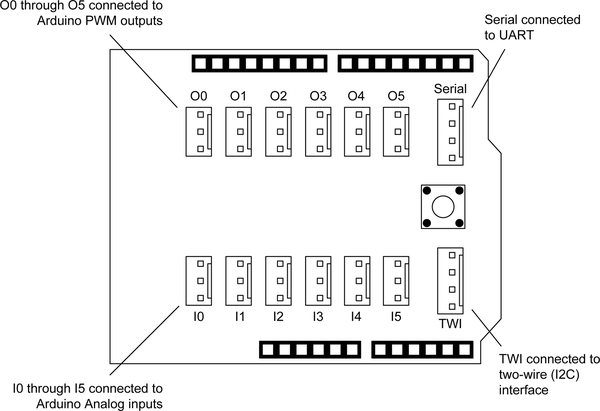
Figure 8-6. TinkerKit I/O expansion shield connectors
Although the status of TinkerKit is currently in limbo, the products are still available from Mouser and other sources. The software libraries are available on GitHub.
- TinkerKit Mega Sensor Shield
-
The TinkerKit Mega Sensor Shield (Figure 8-7) is designed to bring out the additional I/O pins of an Arduino Mega, Mega2650, or Mega ADK board. It utilizes long-lead pin sockets for stackability, and a reset switch is provided on the PCB. It is essentially a larger version of the TinkerKit shield described previously.
- Grove Base Shield
-
A module and shield system gaining popularity among Arduino users are the Grove components sold by Seeed Studio. These are a large number of modules to select from, and a base board is available that features an integrated Arduino-compatible ATMEGA328p MCU. The board, designed by Linaro.com (96Boards.org) is shown in Figure 8-8.
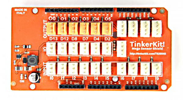
Figure 8-7. TinkerKit I/O expansion shield for Mega-type Arduino boards
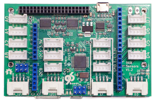
Figure 8-8. Grove Base Shield
Seeed Studio also sold a passive (that is, no onboard MCU) expansion shield for the Grove module system, but while you may still be able to find some, they have been discontinued. The Passive Seeed Studio Grove Base Shield is shown in Figure 8-9.
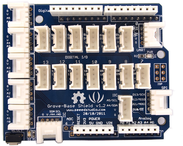
Figure 8-9. Seeed Studio Passive Grove Base Shield
For more information about the Grove series of modules and compatible interface shields, visit the Seeed Studio wiki.
- CuteDigi Sensor Expansion Shield
-
Technically an I/O extension shield rather than a true expansion shield, this shield from CuteDigi (Figure 8-10) uses pin headers instead of connectors to bring out the signals from an Arduino Mega-type board. It is not stackable, but given the vertical arrangement of the pins on the PCB it wouldn’t make sense to stack something on top of this board. The labels on the PCB are clear and the functions obvious.
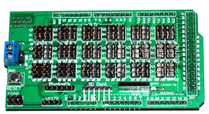
Figure 8-10. CuteDigi Mega extension shield with SD flash and bluetooth connections
This shield is interesting in that it also includes a header with right-angle pins for connecting to an SD-type flash card carrier, and there is a pin header for use with a Bluetooth module as well. The connectors employ the same S-V-G (signal, V+, ground) scheme seen on other I/O extension shields.
I/O Expansion Shields
Unlike the I/O extension shields listed in the previous section, an I/O expansion shield provides additional I/O capabilities, usually in the form of discrete digital I/O (although some shields do have analog capabilities). Because these shields have active circuitry in addition to various connectors, they are more expensive than extender shields. Their big advantage lies in providing multiple I/O channels using only an I2C or SPI connection to the underlying Arduino board. This leaves the remaining pins on the Arduino available for other applications.
- Macetech Centipede Shield
-
The Macetech Centipede Shield (Figure 8-11) uses the Arduino I2C interface to provide 64 general-purpose discrete digital I/O pins. The pins are arranged as 4 groups of 16 pins, with each group controlled by an I2C I/O expander chip.
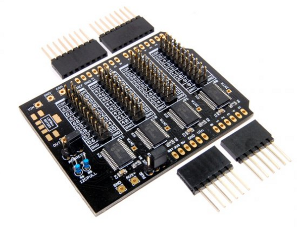
Figure 8-11. Macetech Centipede I/O expansion shield
Figure 8-12 shows the layout of the I/O pins used on the Macetech shield. Each of the MUX (multiplexer) ICs controls 16 pins, or one block of I/O pins. Notice how the pin numbering is arranged on each block, with the numbering “wrapping” around the block.
- LinkSprite I/O Expander Shield
-
This is a stackable shield that uses an MCP23017 I2C I/O expander chip to provide an additional 16 discrete digital I/O pins (Figure 8-13). Note that this shield is designed for use with R3-style Arduino boards and uses the last two pins (9 and 10, SDA and SCL) on the extended connector found on Uno R3 and Leonardo boards.
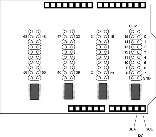
Figure 8-12. Macetech Centipede I/O pin layout
The expanded I/O pins are arranged as two sets of eight discrete channels, designated GPIOA and GPIOB. As shown in Figure 8-14, these are positioned next to the digital I/O pin socket strips. This might make it awkward to use these pins if another shield is stacked on top of this one, so be aware of little “gotchas” like that. But if it’s the only shield, or the top shield in a stack, then it shouldn’t be a problem.
- Numato Digital and Analog IO Expander Shield
-
The digital and analog expander shield from Numato (Figure 8-15) provides 28 additional discrete digital I/O channels and 16 analog inputs using two MCP23017 I2C digital I/O chips and an NXP 74HC4067 analog multiplexer IC for analog signals.
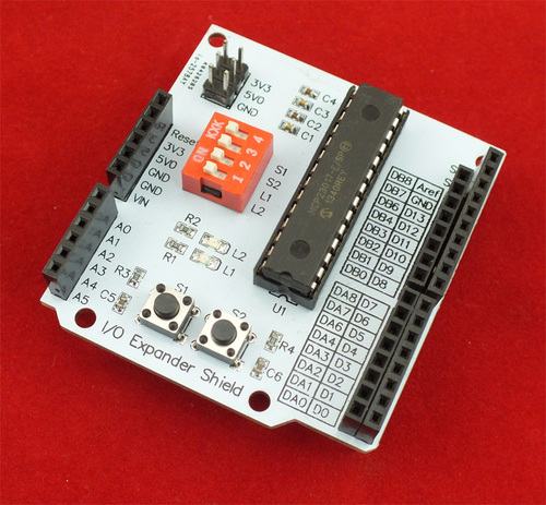
Figure 8-13. CuteDigi 16-channel I/O expander shield
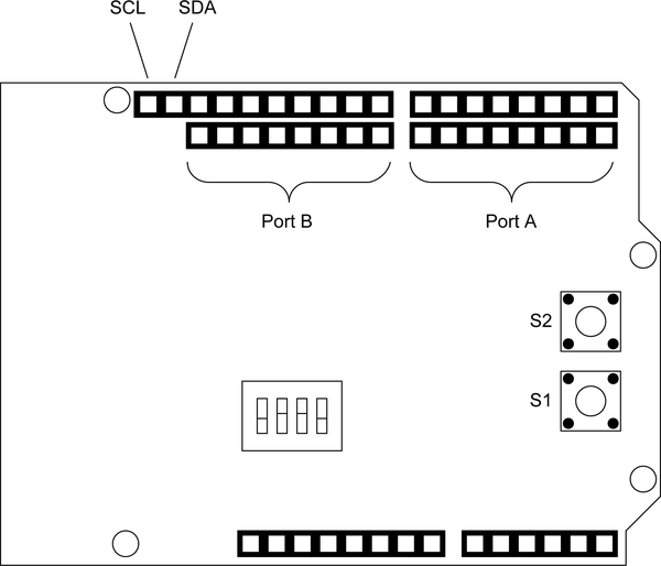
Figure 8-14. CuteDigi 16-channel I/O expander shield pin layout
As shown in Figure 8-16, the primary interface to an Arduino is via the I2C interface on pins A4 and A5. The interrupt pins on the MCP23017 chips are also brought out on the digital I/O pin blocks. The six pin headers in the middle of the board are used with jumper blocks to select the I2C addresses of the two MCP23017 chips.
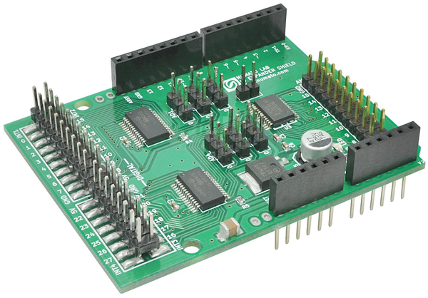
Figure 8-15. Numato digital and analog I/O expansion shield
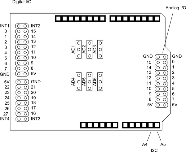
Figure 8-16. Numato I/O expansion shield pin layout
Relay Shields
Relay shields are available with one or more relays. The relays used in these shields may be 5- or 10-ampere types like the ones shown on the shields listed here, as well as reed relays in DIP packages.
Note
When evaluating relay boards take care to note what the vendor gives as maximum ratings for the shield. The modular relays used on a shield may have contacts rated for 10A at 120V AC, but the connectors and traces on the shield PCB may not be rated for that level of current. Also note that not all vendors will derate the current capacity to account for PCB or connector constraints. It is prudent to take a moment and look up the relay specification from the part number shown in the vendor’s photos or schematics. You might want to think twice about a shield where the part numbers have been removed or otherwise obliterated (and that goes for any shield, not just relay shields).
- DFRobot Relay Shield
-
This shield shows how the form factor of a shield can be “tweaked” to accommodate larger parts. In the case of the DFRobot relay shield (Figure 8-17), the four relays are mounted in an expanded part of the shield PCB. The relay contacts are rated at 3A nominal at 24V DC or 120V AC, with 5A maximum current capacity. This is a stackable shield, although the vertical I/O pins may be difficult to use with a shield on top of this board.
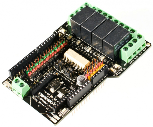
Figure 8-17. DFRobot relay shield
The board uses a set of jumpers to route the digital signals for the relay drivers and an XBee module’s pins, shown in Figure 8-18. All of the Arduino’s digital and analog pins are brought out in blocks of pin headers.
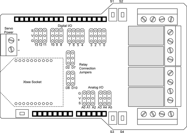
Figure 8-18. DFRobot relay shield board layout
- Numato Relay Shield
-
This shield (Figure 8-19) uses two low-power modular relays with contacts rated for 1A at 120V AC and 2A at 24V DC. The Numato shield uses the Arduino’s digital pins 2 and 3. Miniature terminal blocks bring out the relay terminals. This is a stackable shield.
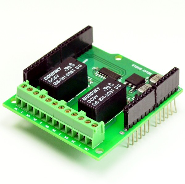
Figure 8-19. Numato relay shield
- Seeed Studio Relay Shield
-
The Seeed Studio relay shield (Figure 8-20) uses four relays with contacts rated at 10A at 120V AC. It uses the Arduino’s digital output pins 4 through 7, one per relay. Each relay has an LED to indicate activity. This is a stackable shield.
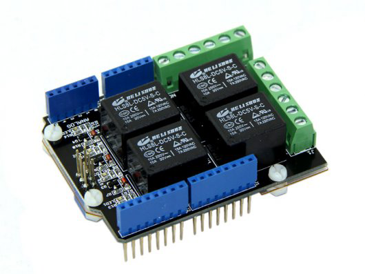
Figure 8-20. Seeed Studio relay shield
Signal Routing Shields
There aren’t a lot of signal routing shields available. What shields are available typically come in one of two styles: passive routing or active MUX (multiplexer) routing.
- Adafruit Patch Shield
-
The passive patch shield available from Adafruit, shown in Figure 8-21, allows you to route signals between four RJ45-type connectors (also known as 8P8C connectors) and the underlying Arduino board using short patch wires inserted into blocks of pin sockets.
Note
This is a kit, not an assembled shield. The photo shows what the assembled shield should look like.
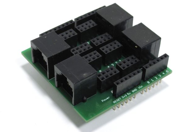
Figure 8-21. Adafruit patch shield
The main idea behind the patch shield is to route specific signals to and from an Arduino through conventional Ethernet cables to remote connection points, as shown in Figure 8-22. The kit includes four satellite PCBs with 8P8C (RJ45) jacks and pins to connect to a solderless breadboard, a sensor module, or another Arduino. There are no active components on this shield or the satellite boards; it just routes signals.
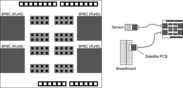
Figure 8-22. Adafruit patch shield layout and usage
- Mayhew Labs Go-Between Shield
-
The Go-Between shield (Figure 8-23) employs a matrix of solder jumper locations to route signals from the base Arduino or a lower shield to an upper shield. It could be handy if you want to stack two shields that use the same pins for I/O functions. If the pins of the upper shield could be moved to different pins on the lower shield without any shield hacking, that would solve the problem. A minor change to the software would make it all work.
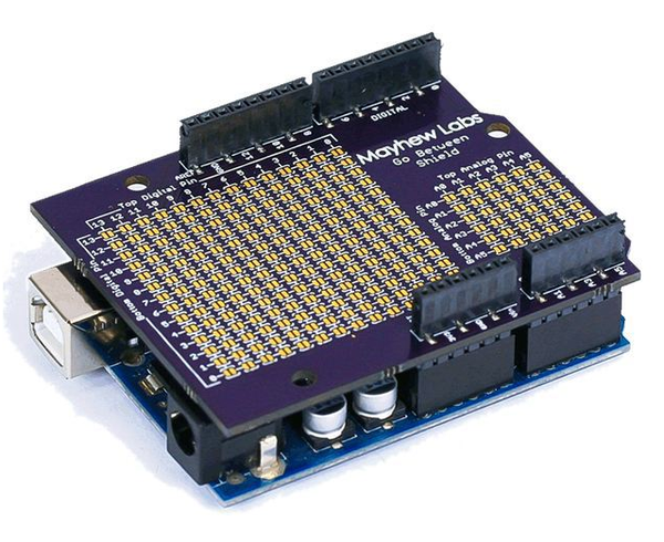
Figure 8-23. Mayhew Labs Go-Between shield
- Mayhew Labs Mux Shield II
-
The Mux Shield II (Figure 8-24) is an active shield that supports up to 48 inputs or outputs using three Texas Instruments CD74HC4067 multiplexer chips and three output shift register circuits. The board uses four of the Arduino digital pins to control the MUX chips and shift registers. The default digital pins are 2, 4, 6, and 7. Pins A0, A1, and A2 of the Arduino are used as inputs from the MUX chips.
The 3 × 16 array of pads (Figure 8-25) can be used with pin headers or pin sockets. Each channel is bidirectional, routing signals to a common output or from a common input. Each MUX chip is similar to an array of switches, each with a slight resistance while closed, and a very high impedance when open.
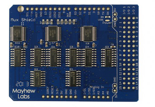
Figure 8-24. Mayhew Labs active signal multiplexer shield (Mux II)
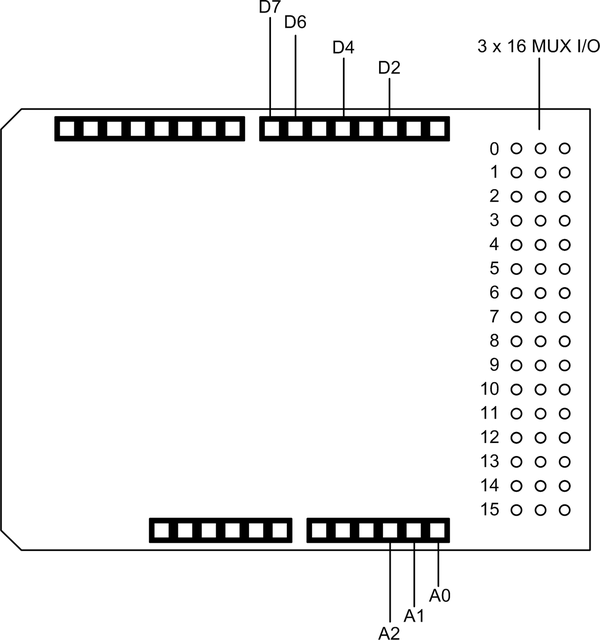
Figure 8-25. Mayhew Labs signal multiplexer shield pins
- Mayhew Labs Mux Shield
-
Similar to the shield described previously, this active multiplexer shield provides 48 programmable I/O lines using three TI CD75HC4067 MUX chips (see Figure 8-26). It also provides two large blocks of pin socket headers to access the signals. The Arduino’s digital pins 2 through 5 are used to address the MUX chips, and pins A0, A1, and A2 are the analog inputs from the MUX chips. This is a stackable shield.
Memory
Without a doubt, the SD and microSD flash memory formats are the most popular way to add some file-like memory to an Arduino. External flash memory is accessed through the SPI interface, and an SD or microSD socket is often found as an added feature on shields that are using the SPI for the primary function (Ethernet, WiFi, USB host, etc.). Removable flash memory is a convenient way to log data from a standalone Arduino, and then later load the data into your PC and do whatever it is you want to do with it.
These descriptions don’t have accompanying diagrams, mainly because the SD or microSD interface to an Arduino is just an SPI interface. One shield has the select signal on an unusual pin. That might create a conflict with existing software.
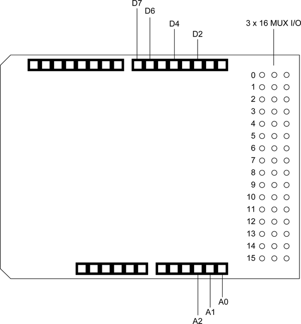
Figure 8-26. Mayhew Labs active signal multiplexer shield (Mux)
- Seeed Studio SD Card Shield
-
Designed for full-size SD flash memory cards, this shield (shown in Figure 8-27) can easily be used with microSD cards with an adapter. Arduino digital pins D4, D11, D12, and D13 are used for the SPI interface. The shield also brings out the ICSP, I2C, and UART pins to connectors on the PCB. This is a stackable shield.
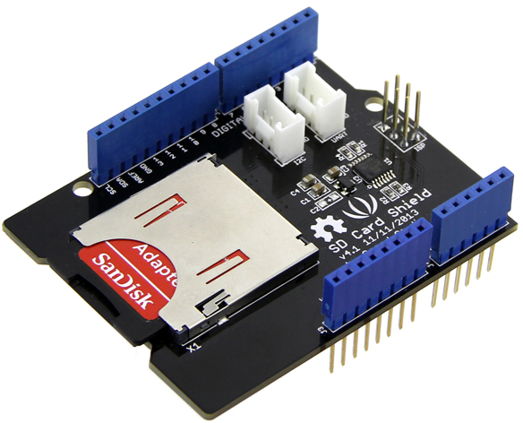
Figure 8-27. Seeed Studio SD memory card shield
- SHD-SD SD Card Shield
-
This SD shield, pictured in Figure 8-28, features a small prototyping area for adding your own circuitry. It can accept microSD cards with an adapter. The shield uses the D10, D11, D12, and D13 pins on an Arduino for the SPI interface to the SD memory. It also uses the 3.3V DC from the Arduino. The shield is shorter than a conventional shield, with a baseline Arduino pin arrangement. It is a stackable shield.
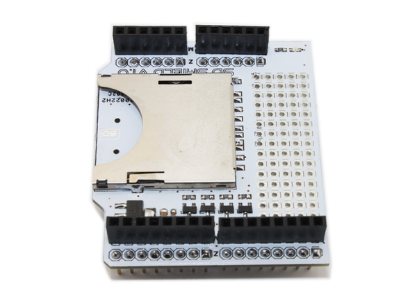
Figure 8-28. Short SD card shield
- SparkFun microSD Shield
-
The SparkFun microSD shield (Figure 8-29) accepts only microSD cards. It includes a large 12 by 13 prototyping area. It does not come with pin sockets or headers, but these can be ordered separately. It uses the D10, D11, D12, and D14 pins on an Arduino.
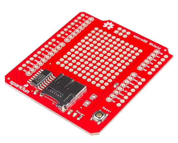
Figure 8-29. SparkFun microSD shield
Communication
Although an Arduino might have a USB interface (most do) with the ability to act as a serial port from the host system’s perspective, or an Ethernet jack as found with the Arduino Ethernet, a basic Arduino like an Uno or Leonardo doesn’t really have much in the way of plug-and-play data communications interfaces. It is possible to attach level-shifting chips and use the built-in UART or write a so-called “bit-banger” to send serial data, but it is sometimes more convenient to use something with an SPI interface to the Arduino and let it do the serial sending and receiving. For other forms of data communication the necessary external hardware can get rather involved, so it’s definitely easier to use a ready-made shield.
Serial I/O and MIDI
Although even Ethernet can be considered a form of serial data communication, serial I/O here refers to the old standards of RS-232 and RS-485. While these are old, they are ubiquitous. Older PCs have RS-232 connectors (and quite a few newer models also have at least one), and RS-485 is common in instrumentation, testing, and distributed measurement systems.
- CuteDigi RS232 Shield
-
This RS-232 shield (Figure 8-30) employs a MAX232 IC to perform the signal-level shifting necessary to send and receive RS-232–compatible signals. A bank of jumpers is used to configure the serial interface, and any two digital pins from D0 to D7 on an Arduino may be used for the serial interface. With the supplied pin sockets installed it becomes a stackable shield.
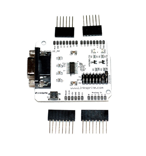
Figure 8-30. CuteDigi RS232 shield
- CuteDigi RS-485 Shield
-
CuteDigi’s RS485 shield (Figure 8-31) uses a MAX481CSA chip to provide the RS485 electrical interface using the Arduino’s Rx and Tx ports (D2 and D3, respectively). A mounting position is provided in the shield PCB for an optional DB-9 connector. This is a stackable shield.
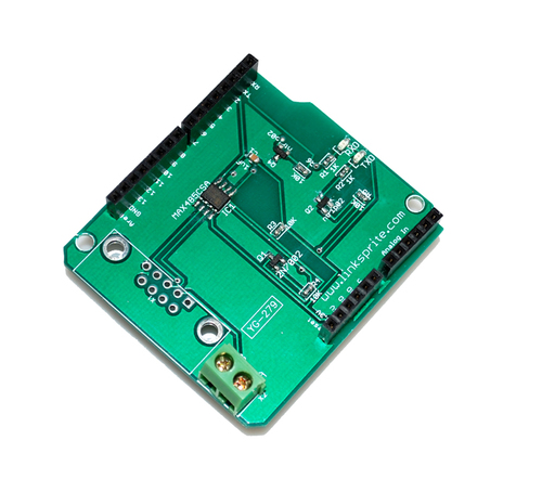
Figure 8-31. CuteDigi RS485 shield
- SparkFun MIDI Shield
-
MIDI is a venerable serial protocol that has been around for over 30 years. It is used to control musical synthesizers, sequencers, drum machines, and mixers, among other things. The SparkFun MIDI shield (Figure 8-32) uses the Arduino’s USART pins to send and receive MIDI event messages.
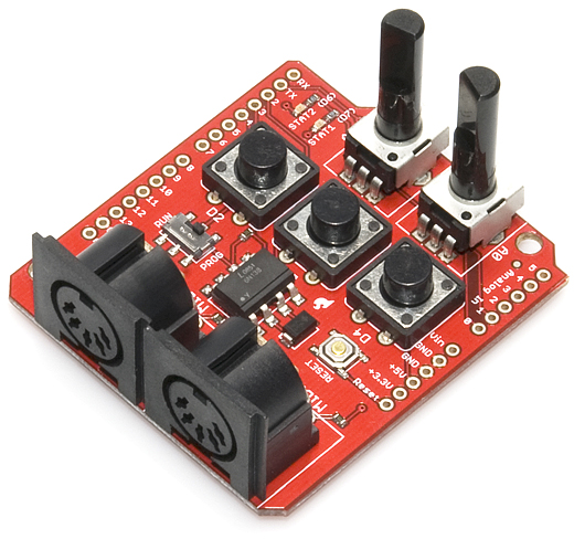
Figure 8-32. SparkFun MIDI shield
The MIDI shield uses the D0 and D1 pins (Rx and Tx, respectively) for MIDI serial I/O. It also has pushbuttons on D2, D3, and D4; LEDs connected to D6 and D7; and potentiometers connected to A0 and A1.
Ethernet
Ethernet shields are popular, and the Arduino IDE comes with a fairly comprehensive Ethernet library suite (see Chapter 7 for details). Be aware that the communication between the AVR MCU on the Arduino board and the Ethernet controller on the shield uses the SPI interface. The AVR does not have DMA (direct memory access) capability, and it has no external memory to directly access in any case.
With Ethernet shields that use SPI as the interface with an Arduino there is an inherent limit on how fast data can move between the AVR MCU and the Ethernet I/O chip, and consequently on how fast data can move over the Ethernet connection. It is simply not possible to get 100 Mb/s (100Base-T) data rates with a processor running at 20 MHz using an SPI interface, and 10 Mb/s (10BASE-T) is an unlikely stretch. 5 Mb/s is a more realistic expectation. The data is still sent out over the physical layer (the actual Ethernet) at 10 Mb/s, just in byte-sized dribbles rather than as a continuous stream. It all depends on how quickly the software running on the AVR can assemble outbound data and send it to the Ethernet chip. So, while it is possible to create a web server that can fit into a tiny enclosure like an old mint tin, it isn’t going to be very fast, and it won’t handle a lot of connections at the same time.
Where the Ethernet interface really shines is when it is used as the end node of a remote sensing or control system. You can attach it to the Internet, implement some password protection, and use it to retrieve data from some remote location. It can be used to report data back to a central controller in an industrial setting such as a factory, or it can be used to sense temperature, humidity, and other parameters for a distributed HVAC (heating, ventilation, and air conditioning) system controller like the one described in Chapter 12.
- Vetco Ethernet Shield with microSD Card Reader
-
This Ethernet shield from Vetco (Figure 8-33) also includes a microSD card carrier and a reset button. The Arduino’s digital pins D10, D11, D12, and D13 are used for the SPI interface used by the WIZnet W5100 Ethernet chip and the microSD card socket. It is a stackable shield.
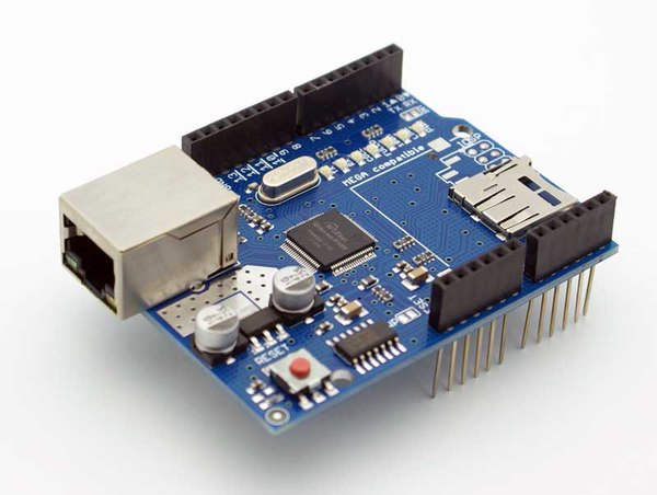
Figure 8-33. Vetco Ethernet shield
- Arduino Ethernet Shield R3 with microSD Connector
-
The official Ethernet shield from Arduino comes with a microSD card reader, a reset button, and all the necessary electronics to implement the Ethernet interface (see Figure 8-34). It uses digital pins D10, D11, D12, and D13 for the SPI interface. This is a stackable shield.
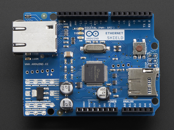
Figure 8-34. Arduino Ethernet shield
Bluetooth
Bluetooth is a low-power, short-range wireless communication technology originally intended to replace the cables strung between a computer and external devices such as printers, keyboards, mice, and so on. While it is still used for these applications, it has found use in many other types of communications applications. There are a number of Bluetooth shields available.
- Bluetooth Shield
-
This shield comes assembled with a Bluetooth module already mounted on the PCB. Note that it is a stackable shield that is shorter than a typical shield. The antenna is the gold pattern emerging from the end of the Bluetooth module (see Figure 8-35). It uses the Rx and Tx pins (D2 and D3, respectively).
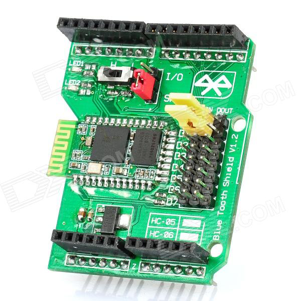
Figure 8-35. DealeXtreme Bluetooth shield
- Seeed Studio Bluetooth Shield
-
This compact, stackable Bluetooth shield (Figure 8-36) uses an Arduino’s Rx and Tx pins. It also brings out the pins for analog and digital signals to interface with sensor modules.
- ITEAD Bluetooth Wireless BT Module Shield Kit
-
This shield (Figure 8-37) uses a standard Bluetooth module, and comes with a prototyping area on the PCB. It is a “short” shield, in that it doesn’t cover the whole length of an Arduino board. It is stackable.
- DFRobot Gravity:IO Expansion Shield
-
This multifunction board from DFRobot (Figure 8-38) combines I/O extension capabilities with a set of pin sockets for a Bluetooth or ZigBee wireless module. It is not a stackable board.
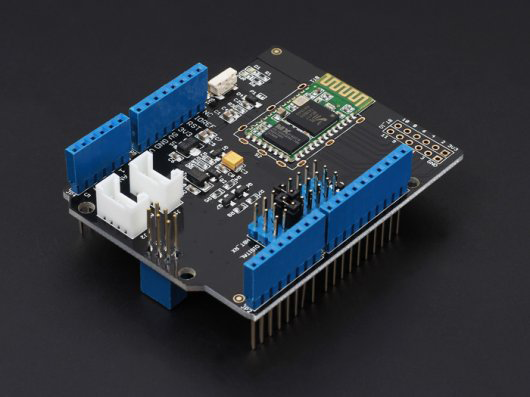
Figure 8-36. Compact Bluetooth shield from Seeed Studio

Figure 8-37. ITEAD Bluetooth shield with prototyping area
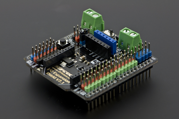
Figure 8-38. DFRobot multifunction shield with Bluetooth
USB
One thing an 8-bit Arduino can’t do is act as a USB host to other USB devices. A USB host shield allows you connect USB devices such as keyboards, printers, some test instruments, and various toys to an Arduino.
- ITEAD USB Host Shield
-
This is a stackable shield with USB host functionality. It also provides pins for the Arduino digital and analog signals, and two 10-pin positions on the PCB for either connectors or pin headers (see Figure 8-39). It is based on a MAX3421E chip with an SPI interface to an Arduino.
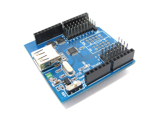
Figure 8-39. USB host shield with I/O connections
- Circuits@Home USB Host Shield
-
This shield (Figure 8-40) supports USB 2.0 full-speed operation and uses an SPI interface to an Arduino. The digital and analog signals from the Arduino are available on the shield’s PCB, and with the right pin sockets it could be stackable. It employs a MAX3421E chip with an SPI interface to an Arduino using pins D10, D11, D12, and D13. It does not come with pin sockets or headers.
- Arduino USB Host Shield
-
Like other USB host shields, this board uses the MAX3421E chip with an SPI interface to the Arduino using pins D10, D11, D12, and D13. Three- and four-pin connectors bring out input and output ports that will work directly with TinkerKit modules (the TinkerKit modules are described in Chapter 9). This is a stackable shield (see Figure 8-41).
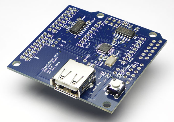
Figure 8-40. Circuits@Home USB host shield
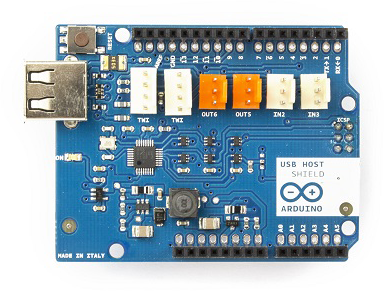
Figure 8-41. Arduino USB host shield with I/O connectors
ZigBee
ZigBee is a popular low-power wireless protocol. Many of the available ZigBee Arduino shields use readily available XBee modules, but most shields will accommodate any RF module with the correct pinout. Some are available with an XBee module, and some are available without. A 1 mW XBee module costs around $25.
- Arduino Wireless SD Shield
-
On this ZigBee shield (Figure 8-42), two inline pin sockets are provided for a Digi XBee module, or any module with a compatible pin arrangement. This shield uses an Arduino’s pin D4 as the select, and pins D11, D12, and D13 for SPI communication. A microSD carrier on the shield also uses the SPI interface.
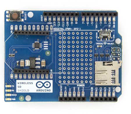
Figure 8-42. Arduino ZigBee shield
- SainSmart XBee Shield
-
This shield comes without an XBee module, but the pin layout will accept a standard XBee module, or any module with a compatible pin arrangement. Note that there is no microSD carrier. This is an offset stacking shield (note the locations of pin headers and pin sockets in Figure 8-43).
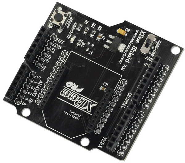
Figure 8-43. SainSmart compact ZigBee shield
- Seeed Studio XBee Shield
-
The XBee shield from Seeed Studio (Figure 8-44) has the expected mounting position for a common XBee module, and it also provides a prototyping area. This shield uses the Rx and Tx pins from an Arduino, and a block of pins for jumpers is used to route the Rx and Tx signals from the Arduino to the wireless module.
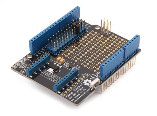
Figure 8-44. SainSmart ZigBee shield with prototyping area
CAN
The Controller Area Network (CAN, also known as CAN bus), is a differential signalling relative of RS-485 found in vehicles, industrial settings, and some military equipment. It is relatively fast (up to 1 Mb/s), incorporates signal collision detection and error detection, and supports multiple nodes. It is used with the OBD-II on-board diagnostics found in late-model automobiles, in electric vehicles, and with distributed sensors in scientific instruments, and has even been integrated into some high-end bicycles.
- Seeed Studio CAN-BUS Shield
-
The CAN interface shield from Seeed Studio (Figure 8-45) utilizes an MCP2515 CAN bus controller with an SPI interface and an MCP2551 CAN transceiver chip. Both a terminal block and a DB-9 connector are provided for the CAN bus signals. The shield also brings out the I2C and UART communications from the Arduino. The pin layout is shown in Figure 8-46.
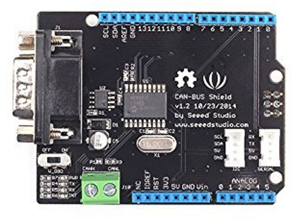
Figure 8-45. Seeed Studio CAN shield with auxiliary I/O connectors
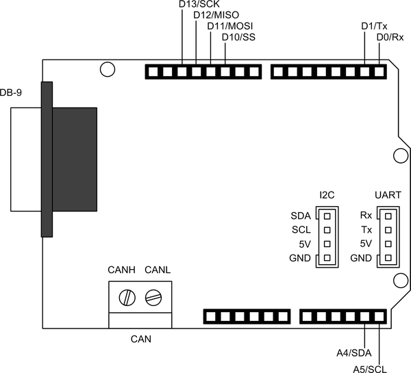
Figure 8-46. Seeed Studio CAN shield with auxiliary I/O pin layout
- SparkFun CAN-BUS Shield
-
This CAN shield from SparkFun (Figure 8-47) incorporates many of the features one might want to use when creating an OBD-II readout and data capture device. It has a DB-9 connector for CAN bus signals, and a 4-pin header also provides the signals. Connection points are provided for an external LCD display and an EM406 GPS module.
An interesting feature is a four-position binary joystick, and it incorporates a microSD flash card carrier. The joystick is connected to the Arduino analog inputs. The CAN chip and the SD flash are separately selected via digital pins D9 and D10. Pins D3, D4, D5, and A0 are not used by the shield. The pin layout is shown in Figure 8-48.
- LinkSprite CAN-BUS Shield
-
The LinkSprite CAN shield (Figure 8-49) is physically similar to the Seeed shield. It has both a DB-9 connector and a two-position terminal block for the CAN signals. Pins D10, D11, D12, and D13 are used for the SPI interface to an MCP2515 CAN chip.
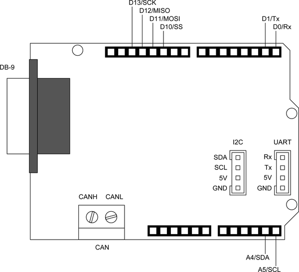
Figure 8-47. SparkFun CAN shield with microSD carrier and digital joystick

Figure 8-48. SparkFun CAN shield I/O pin layout
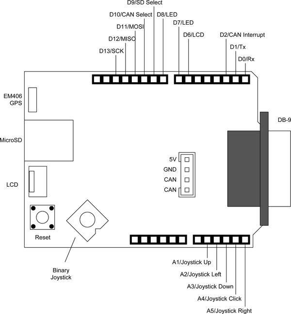
Figure 8-49. LinkSprite CAN shield
Prototyping
If you want to create your own shield you can build a prototype (or even a permanent shield) using a prototyping shield board. This is not the same as the process of creating a shield described in Chapter 10, which involves laying out a PCB for (possible) mass production. Figure 8-50 shows a prototype shield similar to those described in this section with a temperature sensor and a relay mounted on it. A potentiometer is connected to the +5V, ground, and A0 (analog input 0) pins passed through from the underlying Arduino board. The pot controls the temperature set point.
This prototype was used to control an ancient (and very dangerous) portable electric heater that used a bimetallic thermostat that couldn’t seem to hold the temperature to better than +/– 15 degrees. Since the relay is only rated to 10 amperes at 120 VAC and the heating elements were rated for 15 amps, it was used along with a 24 VAC transformer to control a 20-amp contactor. It worked pretty well, and kept my office relatively comfortable during the winter. I plan to add a tilt sensor, output temperature sensor, and fan motion detector to it. Just to be safe.
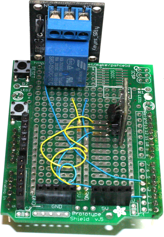
Figure 8-50. Prototype temperature sensor/controller shield
The shields in this section are representative of what is available, and none are particularly complicated. What the Arduino pins are used for is entirely up to you (it is a prototype, after all), so there isn’t much need for diagrams.
- Adafruit Stackable R3 Proto Shield
-
This shield (Figure 8-51) comes as a kit, which means a bare PCB and a bag of parts. It’s not hard to assemble, but some soldering skill is essential.
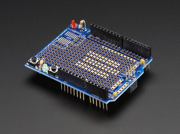
Figure 8-51. Adafruit stackable prototype shield kit
- Adafruit Mega Proto Shield
-
Another kit from Adafruit, this stackable prototyping shield comes with all the bits you can see in Figure 8-52. Note the double rows of solder pads for the connections along the sides of the PCB. This allows you to solder in short-lead pin sockets to gain easy access to the signals from an underlying Mega-type Arduino.
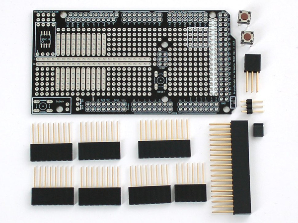
Figure 8-52. Adafruit Mega prototype shield kit
- CuteDigi Assembled Protoshield for Arduino
-
This prototyping shield (Figure 8-53) comes fully assembled. It also has pin sockets on the PCB for access to the Arduino signals. This is not a stacking shield.
- CuteDigi Assembled Protoshield for Arduino MEGA
-
Designed to work with a Mega-type Arduino, this shield (Figure 8-54) also features a small-outline (SOIC) mounting location for an IC. This is not a stacking shield.
- CuteDigi Protoshield for Arduino with Mini Breadboard
-
This shield, pictured in Figure 8-55, includes a small solderless breadboard for your own circuit creations.
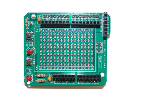
Figure 8-53. CuteDigi prototyping shield
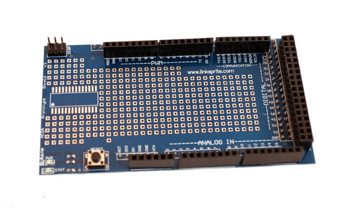
Figure 8-54. CuteDigi Mega prototyping shield
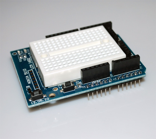
Figure 8-55. CuteDigi prototyping shield with breadboard
Creating a Custom Prototype Shield
You can whip up a workable shield using nothing more than a prototyping PCB and some pin and socket connectors. The size of the PCB doesn’t really matter, so long as the pins line up with the sockets on an Arduino board.
- Adafruit DIY Shield Kit
-
If there was award for the simplest shield kit, this would definitely be at the top of the list of contenders. Consisting of a prototyping PCB and four long-lead pin socket connectors (Figure 8-56), this shield lets you put anything you like on it. This is handy for prototyping a new shield design, or just quickly throwing something together, and it’s great for using an existing module of some type that was never intended to be connected to an Arduino.
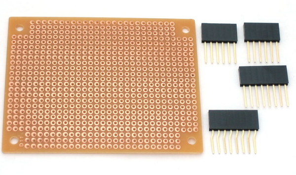
Figure 8-56. Adafruit DIY shield kit
Unfortunately the product has been discontinued by Adafruit, but all you need is a prototyping PCB (these are readily available from multiple sources) and the pin sockets, which Adafruit and other vendors carry. Since the pin pads on an Arduino use industry-standard 0.1 inch (2.54 mm) spacing, it’s easy to make something with basic prototyping supplies that can serve as a shield.
Motion Control
Motion control is a big area of interest in the Arduino domain. From programmable mobile robots to CNC engravers, 3D printers to laser scanners, and even automated sun-following tracking controllers for solar panels and kinetic sculptures, Arduinos have been used to control DC motors, servos, and stepper motors from the outset. As you might expect, a number of shields are available for each type of motor, and this is just a small sampling of what’s available.
DC and Stepper Motor Control
Motor controller shields based on an H-bridge (a type of solid-state current routing switch) can usually be used to control either brush-type DC motors or stepper motors. Basically, these types of shields can be used to control any inductive DC load, including solenoids and relays.
- Rugged Motor Driver shield
-
The Rugged Motor Driver Shield from Rugged Circuits (Figure 8-57) can drive either two brush-type DC motors, or one bipolar stepper motor. It is rated for up to 30V at 2.8A peak current. The shield uses the D3, D11, D12, and D13 pins for enable and direction control inputs. The enable inputs can be driven with a PWM signal for smooth control of a DC motor. Check the website for more details regarding current handling and software.
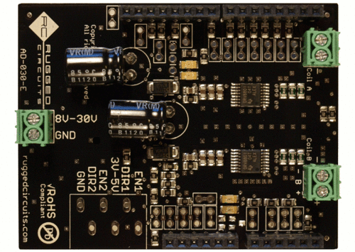
Figure 8-57. Rugged Motor Driver shield
- SainSmart Motor Drive Shield
-
The SainSmart motor shield (Figure 8-58) is based on an L293D four-channel driver IC. It can drive four brush-type DC motors or two stepper motors at up to 10V. It features terminals for an external power supply. Check the website for more details regarding current handling and software.
- Arduino Motor Shield
-
The motor shield from Arduino.cc (Figure 8-59) is based on an L298 dual-driver IC. It can be used with relays, solenoids, DC motors, and stepper motors. An interesting feature is the ability to measure current consumption, which can be handy for detecting a stalled motor. Also note that it has modular connectors that are compatible with various TinkerKit modules (described in Chapter 9).
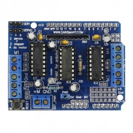
Figure 8-58. SainSmart L239D Motor Drive shield

Figure 8-59. Arduino motor shield
PWM and Servo Control
The small servos used in RC models and small-scale robotics work by positioning an armature relative to a series of control pulses of varying width but at a steady frequency. The width (the “on” time) of the pulses determines the rotation angle of the servo. A PWM/servo shield can also be used to drive a DC motor, precisely control the brightness of one or more LEDs, or operate a linear actuator.
- 16-Channel 12-bit PWM/Servo Shield
-
This shield (Figure 8-60) utilizes a PCA9685 16-channel PWM controller IC with an I2C interface. It has the ability to generate a unique programmable PWM signal on each output, and it doesn’t require the constant attention of the Arduino.
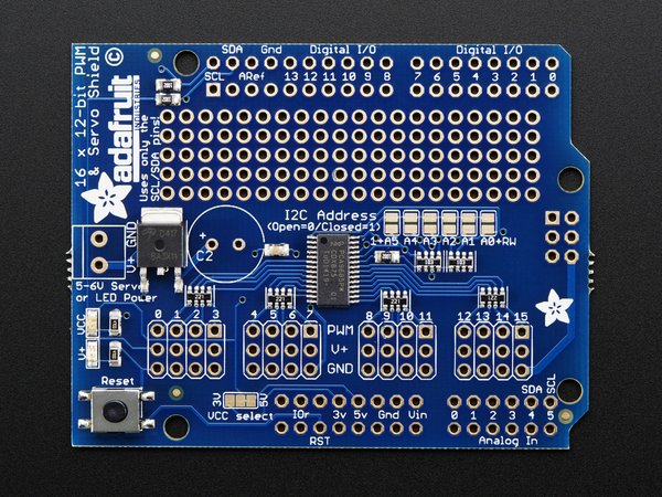
Figure 8-60. Adafruit PWM/servo shield with I2C interface
- LinkSprite 27-Channel PWM Servo Shield
-
This shield from LinkSprite (Figure 8-61) uses an STM32F103C8T6 microcontroller IC to generate up to 27 unique PWM outputs. It is worth noting that the STM32F103C8T6 is an ARM Cortex-M3 32-bit RISC device with up to 128 KB of flash memory and 20 KB of SRAM. The microcontroller on this shield is actually more computationally powerful than the AVR on the Arduino it is mounted on. It communicates with an Arduino using the SPI interface.
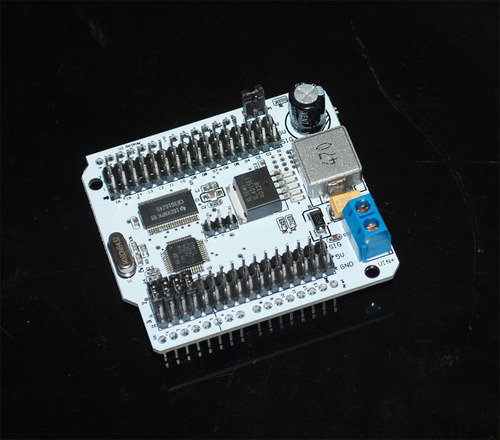
Figure 8-61. LinkSprite servo shield
- SparkFun PWM Shield
-
The PWM shield from SparkFun (Figure 8-62) utilizes a TLC5940 IC and is capable of producing 16 PWM outputs. The TLC5940 is capable of driving LEDs or servo motors. It uses an SPI-type clocked serial interface, but only receives data. More information and software libraries are available from SparkFun.
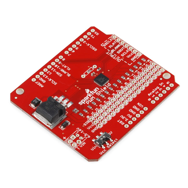
Figure 8-62. SparkFun PWM shield
Displays
Display shields for Arduino boards might contain LED (light-emitting diode) readouts, LED arrays, an LCD (liquid-crystal display), or a color graphical display. Some of the shields utilize multiple digital outputs from an Arduino; others use the SPI or TWI (I2C) interfaces. Whatever it is you want to display, chances are there’s a display shield that will do the job.
LED arrays
By itself a single LED array is fun, but when they’re set side-by-side it is possible to create marquee displays in a variety of colors. For more information about the shields listed here, refer to the websites for each:
-
Adafruit LoL Shield (Figure 8-63)
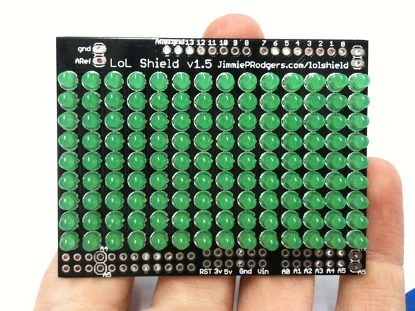
Figure 8-63. Adafruit 9 × 14 LED array shield
-
Solarbotics SMD LoL Shield (Figure 8-64)
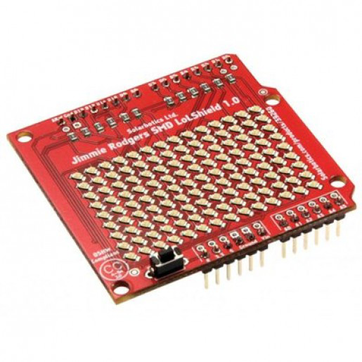
Figure 8-64. Solarbotics 9 × 14 LED array shield
-
Adafruit NeoPixel Shield (Figure 8-65)
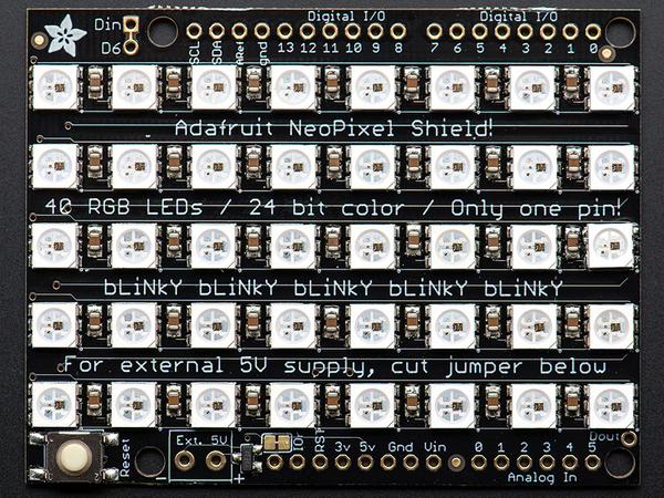
Figure 8-65. Adafruit 40 RGB LED pixel matrix
7-segment LED displays
The 7-segment LED display has been around for almost as long as there have been LEDs. While now considered rather quaint, the 7-segment display still has a role to play when you need big, bright digits you can easily see from across the room. Also check out the multifunction shield listed in “Miscellaneous Shields”, which features a 4-digit numeric LED display.
-
4x 7-Segment Arduino Compatible Digit Shield (Figure 8-66)
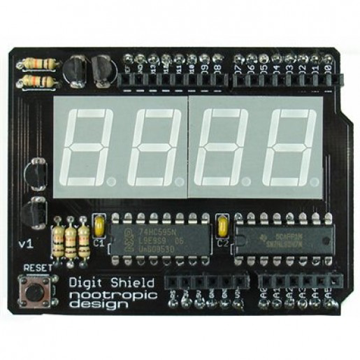
Figure 8-66. Nootropic Design 7-segment display shield
LCD displays
Many low-cost character-based LCD shields utilize 16 × 2 (16 characters in 2 rows) displays with white letters on a blue screen, red letters on a black screen, or black letters on a green screen. Other combinations are also available, including 16 × 4 and 20 × 4 configurations. Most of these types of shields are based on the Hitachi HD44780 LCD controller, or something similar.
There are also pixel-addressable and bitmap-capable LCD displays available. Some of these, like the popular Nokia 5110, are available from various vendors and are easy to interface to an Arduino. You can also find displays with resolutions of 128 × 64 and 160 × 128 pixels without looking too hard, but not many of these are available in the form of an Arduino-compatible shield. See Chapter 9 for more information about bare (nonshield) display components.
- SainSmart LCD Keypad Shield
-
This is a common LCD shield design, shown in Figure 8-67, that uses a 16 × 2 LCD display module and the Hitachi HD44780 LCD controller (the display module is available separately, and one is used in the signal generator in Chapter 11 and in the thermostat in Chapter 12).
This LCD shield uses a voltage divider for the five pushbutton switches, so each button press results in a different voltage. Figure 8-68 shows how this works. The advantage of this approach is that five switch inputs are routed through one analog input.
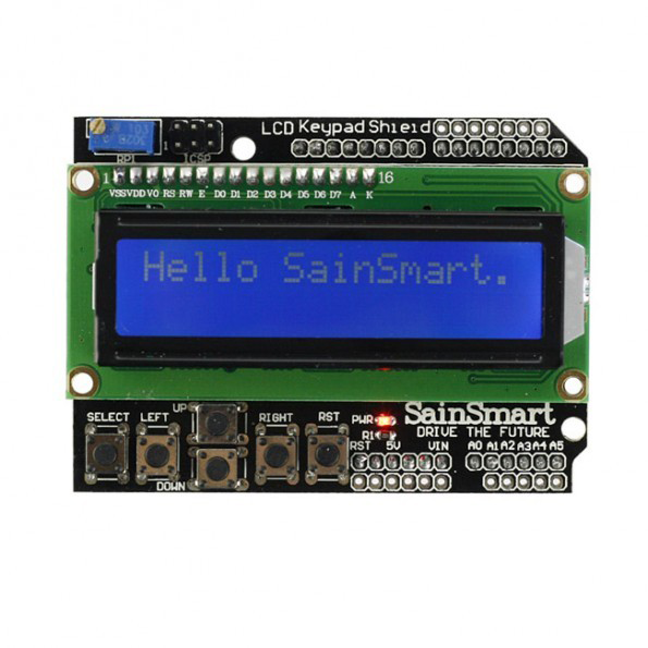
Figure 8-67. SainSmart 16 × 2 LCD keypad shield
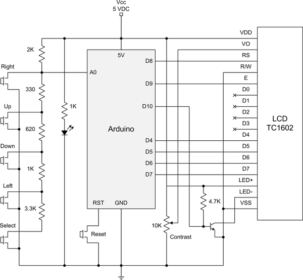
Figure 8-68. SainSmart LCD shield schematic
- DFRobot LCD Keypad Shield
-
This is similar to the SainSmart LCD shield, except with analog pin connections to the underlying Arduino (see Figure 8-69). According to the vendor’s documentation the additional pins are mainly intended for interfacing to an APC220 radio module or a Bluetooth module.
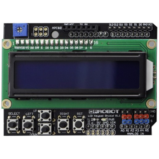
Figure 8-69. DFRobot 16 × 2 LCD keypad shield with analog pins
- Adafruit LCD Shield Kit
-
The 16 × 2 LCD shield kit from Adafruit, shown in Figure 8-70, uses the I2C interface and an MCP232017 I/O expander IC (also used in Chapter 10) to control the LCD display. This results in the shield only using two of the Arduino’s pins, A4 and A5, for the I2C interface. The LCD and the pushbuttons are all connected to the MCP23017 IC, and it does not use a resistor divider. Note that this is a kit, but it’s not too hard to assemble.
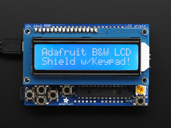
Figure 8-70. Adafruit LCD shield kit with 16 × 2 character display
- Nokia LCD5110 Module with SD
-
This shield, pictured in Figure 8-71, combines a Nokia 5110 LCD display with an SD flash card socket. It uses pins D3, D4, D5, D5, and D7 for the display, and pins D10, D11, D12, and D13 for the SD card. Pins D0, D1, and D2 are available for other applications.
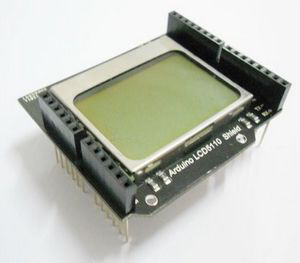
Figure 8-71. Nokia 5110 LCD shield from Elechouse
Unlike the 16 × 2 character-based displays, the 5110 is a graphics-capable LCD with a 48 × 84 display area. Originally manufactured for cell phones, all the currently available units are surplus. Some may have scratches or other slight blemishes. Also bear in mind that when they are gone, that’s it. So, it’s not a good idea to design a new product using these, but they are fun to play with and they are relatively inexpensive.
TFT displays
The TFT LCD (thin-film transistor liquid crystal display), or just TFT for short, is a common display type found in computer monitors, cash register displays, cell phones, tablets, and just about anything else with a color graphical display. A color TFT shield for an Arduino can display thousands of colors at resolutions such as 240 × 320 pixels. Larger displays are available, but these generally don’t fit on a shield. TFT shields are generally inexpensive; most use an SPI interface, and some have a parallel digital interface for high-speed image generation.
- ITEAD 2.4” TFT LCD Touch Shield
-
This shield, pictured in Figure 8-72, uses a parallel digital interface with an Arduino. An 8-bit interface is used with an S6D1121 TFT controller on the shield, and the touchscreen functions are handled by the TSC2046 chip. For additional detailed information, refer to the vendor’s website.
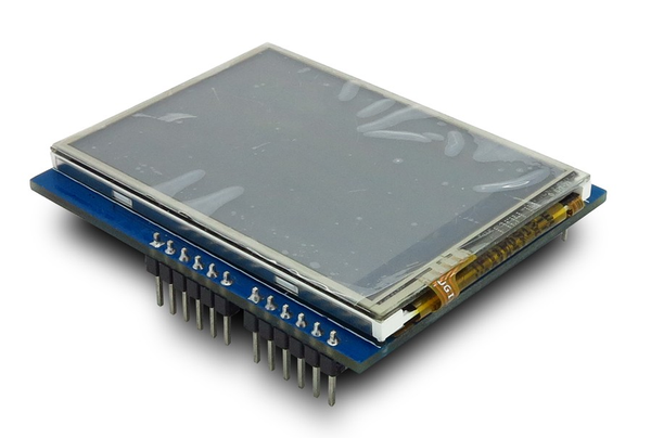
Figure 8-72. ITEAD 2.4 inch color TFT shield with touchscreen
- Adafruit 2.8” TFT Touch Shield
-
The 2.8 inch TFT shield from Adafruit (Figure 8-73) uses a high-speed SPI interface for both an ILI9341 display controller with a built-in video RAM buffer and an STMPE610 touchscreen controller. It also incorporates a microSD flash card carrier. The shield uses the Arduino digital pins D8 through D13, the touchscreen controller uses pin D8, and the microSD carrier select is on pin D4.
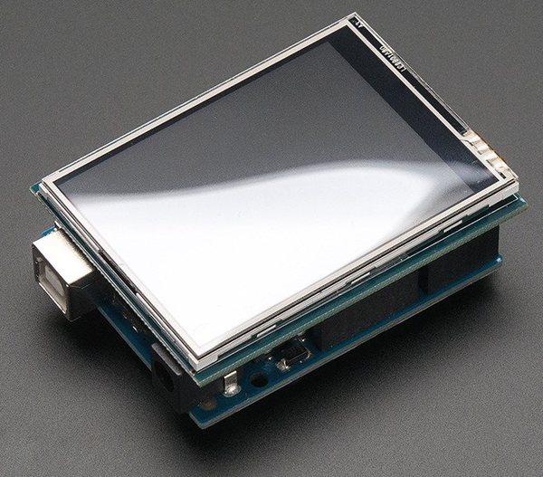
Figure 8-73. Adafruit 2.8 inch TFT shield with resistive touchscreen
Instrumentation Shields
Although not as plentiful as some other shield types, there are instrumentation-type shields available. These include data logging shields, logic analyzers, and precision analog-to-digital (A/D) converters. Instrumentation, in this case, refers to the ability to sense and capture data from the physical world, or generate an analog signal.
There aren’t many shields available with on-board data capture and conversion capabilities, mainly because the AVR MCU on an Arduino already has most of these functions in the chip itself. The built-in A/D converter (ADC) in the AVR MCUs used with Arduino boards has 10-bit resolution, which gives a conversion resolution of 1/1,024 per DN, or digital number. If you need better resolution (12, 16, or even 24 bits, for example), then you will need to consider some type of add-on module or a shield.
- Adafruit Data Logging Shield
-
The Adafruit data logging shield, shown in Figure 8-74, includes an SD flash card carrier and a real-time clock (RTC) chip. The RTC can be powered by a battery when the main power from the base Arduino is off. A small prototyping grid is supplied for custom circuitry. This is not a stacking shield.
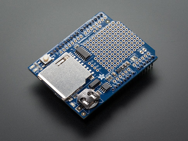
Figure 8-74. Adafruit assembled data logging shield
- Adafruit Ultimate GPS Logger Shield
-
This shield, shown in Figure 8-75, incorporates a GPS receiver as well as an SD flash carrier and an RTC chip. The output of the GPS can be automatically logged to the flash memory card. This is not a stacking shield.
- HobbyLab Logic Analyzer and Signal Generator Shield
-
This is actually a standalone logic analyzer on a shield. It monitors the Arduino signals without interfering with them, which is handy to see what’s happening on the I/O pins. In addition to the logic analyzer capability, it also includes an SPI decoder, a UART decoder, and a one-wire monitor. It does not communicate directly with the Arduino, but uses a USB interface to interact with a host computer. This is a stacking shield (see Figure 8-76).
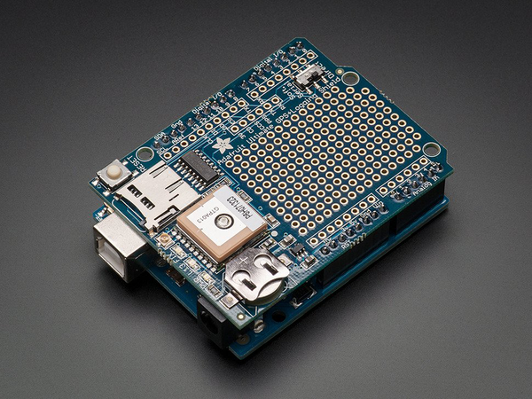
Figure 8-75. Adafruit GPS data logging shield
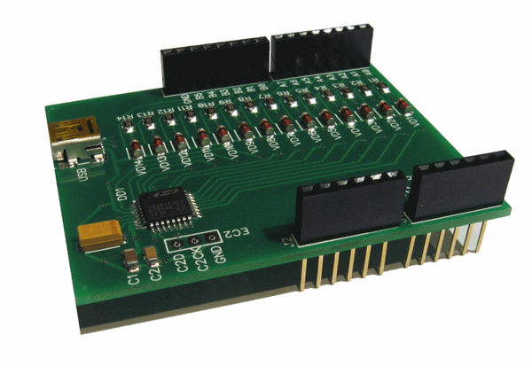
Figure 8-76. HobbyLab logic analyzer and signal generator
- Iowa Scaled Engineering 16-Channel 24-Bit ADC Shield
-
This shield incorporates a 24-bit A/D converter and a precision voltage reference to obtain readings from multiple single-ended or differential inputs. It also has on-board EEPROM for storing and reading calibration and configuration data. It communicates with an Arduino via the I2C (TWI) interface. This is a stacking shield (see Figure 8-77).
- Visgence Power DAC Shield
-
One function the AVR MCU, and by extension an Arduino, lacks is a built-in digital-to-analog converter (DAC). The AVR’s internal ADC incorporates a 10-bit DAC, but the output is not available externally. Although audio output shields are readily available, there don’t seem to be a lot of pure DC output DAC shields available. The Visgence Power DAC Shield (Figure 8-78) provides three channels of analog output with the ability to source up to 250 mA of current.
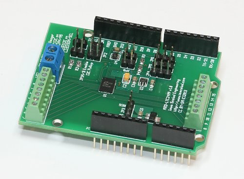
Figure 8-77. Iowa Scaled Engineering 24-bit ADC data acquisition shield
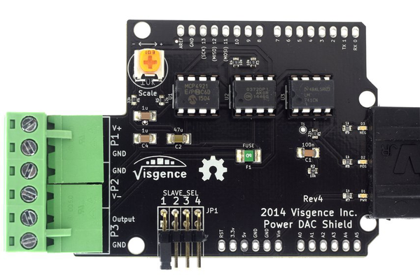
Figure 8-78. Visgence 12-bit Power DAC Shield
Adapter Shields
An adapter shield is used as a physical interface between what would otherwise be two physically incompatible modules. The primary difference between an adapter shield and a signal routing shield (see “Signal Routing Shields”), at least with regard to how the shields are organized in this chapter, is that an adapter is intended as a physical interface. A signal routing shield doesn’t deal with physical differences, just signals.
- Tronixlabs Australia Expansion Shield for Arduino Nano
-
A Nano is every bit as capable as a larger baseline Arduino, but it won’t work with conventional shields. This board, shown in Figure 8-79, addresses that by bringing out the pins from a Nano to pin headers, and optionally to standard pin socket connectors.
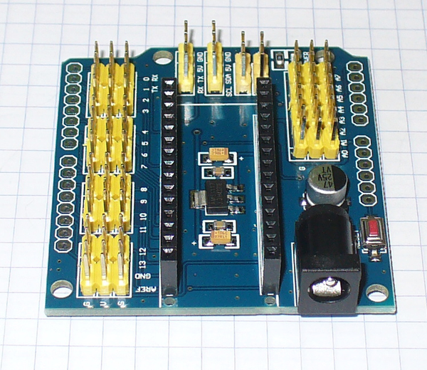
Figure 8-79. Tronixlabs Nano adapter shield
- Arduino Nano I/O Expansion Board (eBay)
-
Another example of a Nano adapter (Figure 8-80). This was found on eBay, but there are others like it available.
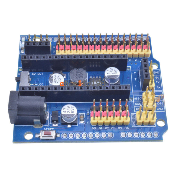
Figure 8-80. Expansion board for Arduino Nano
- Screw Terminal Shield
-
Although not technically a shield, per se, these handy block adapters allow you to connect up to 18-gauge insulated wire to an Arduino. They are readily available from a variety of sources. Notice that these parts have the ability to stack (see Figure 8-81).
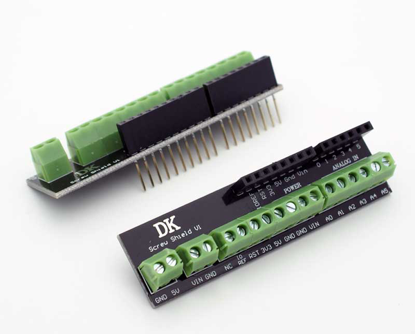
Figure 8-81. Terminal block adapters
Miscellaneous Shields
This section describes some useful shields that don’t really fit into a neat category. I like the so-called “wing shields” because they allow for neater wiring, and the multifunction shield shown here has a multitude of uses.
- Adafruit Proto-ScrewShield (Wingshield)
-
The Wingshield, also known as a Proto-ScrewShield, is a passive shield with two sets of miniature terminal blocks (see Figure 8-82). If you plan to incorporate an Arduino into a commercial product or a laboratory setup, then you may want to consider a shield like this. The screws in the terminal blocks provide for a much more secure and reliable connection than pin jumpers. The prototyping area in the middle of the shield can be used to mount sensor modules, or it can hold a custom circuit. The shield includes a reset switch and an LED, and it’s also a stackable shield. Be aware that this is a kit, so it comes as a bare PCB and a bag of parts. Assembly isn’t hard, but it does require some soldering skill.
- DFRobot Screw ProtoShield
-
Like the Adafruit Wingshield this shield (Figure 8-83) provides screw terminals for each of the signals from an Arduino, but it comes fully assembled. It is also a stackable shield, so you can put it under other shields and still be able to access the terminal blocks.
- DealeXtreme DIY Multifunction Shield
-
This is an interesting shield: it has a 4-digit numeric LED readout; an interface point for an APC220 Bluetooth module; several pushbutton switches connected to Arduino pins A1, A2, and A3; a reset switch; and a potentiometer connected to the A0 input (see Figure 8-84). Four LEDs are connected to digital pins D10, D11, D12, and D13, and a 3 × 4-pin header brings out pins D5, D6, D9, and A5, along with +5V and ground. Unfortunately this shield is also rather poorly documented, and it can take some digging to get useful information. You can find additional information on the HobbyComponents.com forum. A collection of example sketches and a schematic can be downloaded from http://bit.ly/dx-diy-sketch. Note that the directory names in the ZIP archive are all in Chinese, but most of the sketches have comments in English.
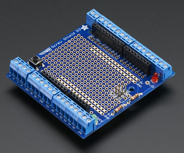
Figure 8-82. Adafruit Wingshield
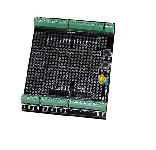
Figure 8-83. DFRobot terminal block shield
The arrangement of the various components of the multifunction shield is shown in Figure 8-85. Note that this is not a stacking shield, which makes sense, because stacking another shield on top would make the LED display useless.
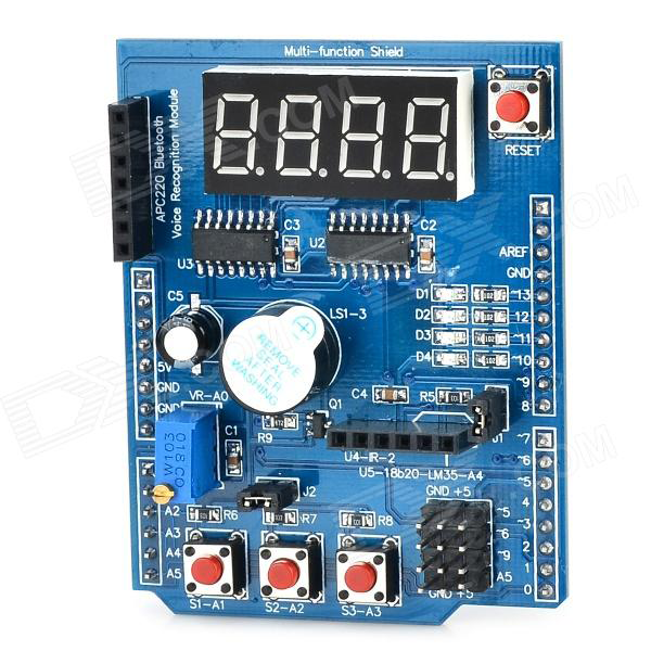
Figure 8-84. DX DIY multifunction shield expansion board
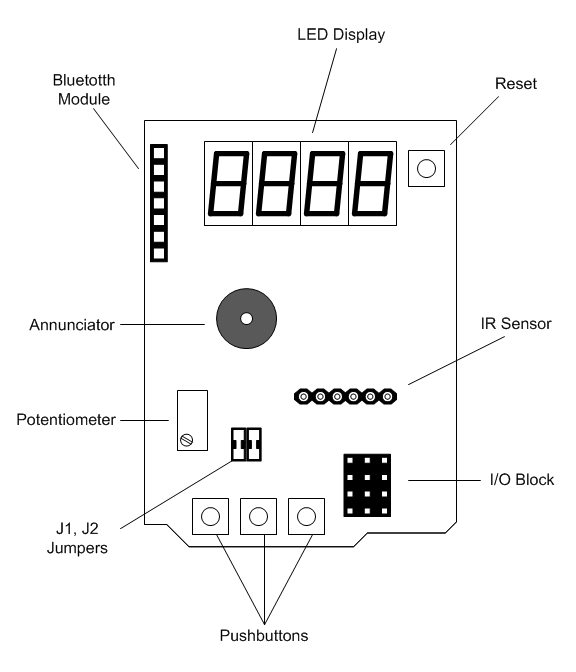
Figure 8-85. Multifunction shield main functional features
The schematic provided for this shield is somewhat cryptic, so I’ve created an alternate version, shown in Figure 8-86. Notice that all the Arduino pins are used by this shield. Table 8-1 lists the Arduino pins and what the multifunction shield uses them for.
This shield is a good example of what one will often encounter with a new shield board. The documentation may be minimal, and much of it might be in a language you don’t understand (Chinese, in this case, but English can be just as difficult for other people). The schematic is correct, but might be difficult to understand at just a glance, and there is no detailed pinout description. (Well, actually, there is now.)
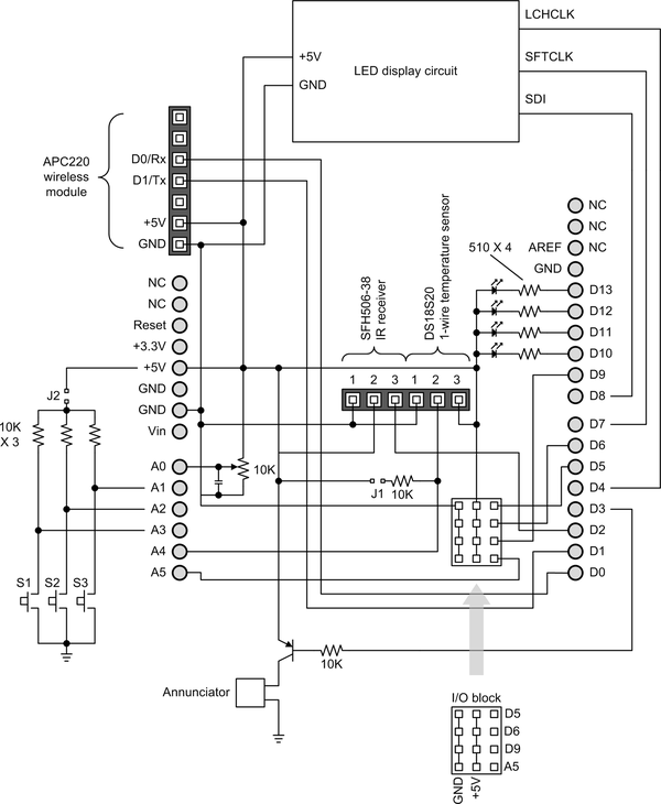
Figure 8-86. Multifunction shield schematic
Table 8-1. Multifunction shield Arduino pin functions Pin Use Pin Use D0
Rx from wireless module
D10
LED
D1
Tx to wireless module
D11
LED
D2
ID received input
D12
LED
D3
Annunciator control
D13
LED
D4
LED display latch
A0
Potentiometer wiper
D5
To D5 on I/O block
A1
Switch S3
D6
To D6 on I/O block
A2
Switch S2
D7
LED display clock
A3
Switch S1
D8
LED display serial data input
A4
Temperature sensor input
D9
To D9 on I/O block
A5
A5 on I/O block
Uncommon Arduino Shields
In addition to a large collection of shields for everything from RS-232 I/O to PWM servo control, there are also shields created for specific applications. Some open source 3D printers utilize an Arduino as the primary controller, and the control interfaces, in the form of a shield, can be found easily. Some of these shields are intended for Mega-type Arduinos and are sized accordingly.
Other uncommon shields don’t really fit into any of the categories in this chapter, but are interesting nonetheless. The Gameduino is an example of this type of shield. It’s essentially a carrier for an FPGA (field-programmable gate array) chip, and has potential for other applications besides playing video games.
- Qunqi CNC Shield for Arduino V3 Engraver
-
This shield, pictured in Figure 8-87, does not come with the motor driver modules, but these are readily available. A typical driver module uses Allegro’s A4988 DMOS microstepping driver chip.
- SainSmart RepRap Arduino Mega Pololu Shield
-
The RepRap 3D fabricator, billed as “humanity’s first general-purpose self-replicating manufacturing machine,” is a compact fabricator that can create parts for other RepRap machines, along with many other things. This shield, shown in Figure 8-88, is designed to replace the electronics on a RepRap-type device and uses a Mega-type Arduino as its processor.
- excamera Gameduino
-
This shield uses a Xilinx FPGA (Figure 8-89) to control the graphics and sound for a homemade games console. An Arduino is used to interface with the controls and direct the game play. The Gameduino is open source, so all the technical details are available, and one could conceivably repurpose the FPGA for something other than games.
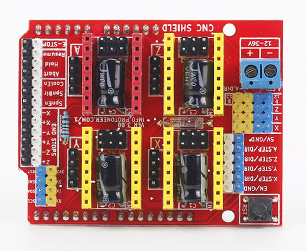
Figure 8-87. Qunqi A4988 driver CNC shield expansion board
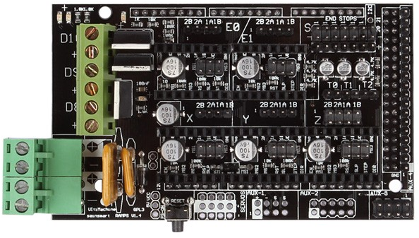
Figure 8-88. SainSmart RAMPS 1.4 RepRap shield for 3D printer
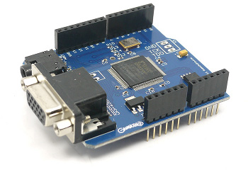
Figure 8-89. excamera Gameduino game controller shield
Sources
Table 8-2 lists the vendors and manufacturers referenced in this chapter. There are, of course, many others not listed here that are also good places to seek useful or novel shields. Entering “Arduino shield” in the Google search bar returns around 400,000 results, so there’s no shortage of places to look for products and information. Just because a vendor or manufacturer is not here doesn’t mean they aren’t worth considering; it’s just that trying to be all-inclusive with a market as volatile as this, with so many different products available, would be a Sisyphean task.
| Name | URL | Name | URL |
|---|---|---|---|
Adafruit |
Macetech |
||
Arduino |
Mayhew Labs |
||
Arduino Lab |
Nootropic Design |
||
Circuits@Home |
Numato |
||
CuteDigi |
RobotShop |
||
DFRobot |
Rugged Circuits |
||
DealeXtreme (DX) |
SainSmart |
||
Elecfreaks |
Seeed Studio |
||
Elechouse |
SparkFun |
||
excamera |
Tindie |
||
Iowa Scaled Engineering |
Tronixlabs |
||
iMall |
Vetco |