
Chapter 9. Modules and I/O Components
While many of the shields available for the Arduino have a lot of interesting and useful functions already built in, they don’t have everything. Nor should they, given that there are a multitude of different types of sensors, controls, and actuator interfaces available that can be used with an Arduino. Many vendors offer single-function add-on sensor components and small PCB modules for the Arduino. These include temperature and humidity sensors, vibration detectors, photo detectors, keypads, joysticks, and even solid-state lasers.
Almost any sensor, control, or actuator device that can be used with a microcontroller can be used with an Arduino. There are some limitations in terms of DC supply voltage, depending on the type of microcontroller in the Arduino itself (3.3V versus 5V), but for the most part this is a relatively minor detail that can be resolved with simple interface electronics and an appropriate power supply.
This chapter looks at both I/O modules and individual components. I/O modules are small PCBs that perform a specific function and use only a few active components, if any at all. They are small, about the size of a postage stamp or less, and they use pins for the connections. They work well with female-to-male or female-to-female jumpers, and in some cases special multiwire cables can be used to connect modules to a shield made for just that purpose. The products from KEYES, SainSmart, and TinkerKit are featured here, primarily because they are good representatives of modules in general. Other modules worth considering are the Grove series of modules and interface shields available from Seeed Studio, and the modules from TinyCircuits.
Individual I/O components cover the spectrum from LEDs to graphical displays, and from mechanical sensors like switches and reed relays to self-contained temperature and humidity sensors. The individual sensors are intentionally covered after the discussion of modules because many of the modules use the components described there. Cross-references are provided between the sections as appropriate.
Most people appreciate neatness and reliability. Unfortunately, using the ubiquitous jumper wires to connect modules and other components can quickly become anything but neat, and the push-on crimp connectors used at each end of the jumper wire have a tendency to work loose from a module’s pins.
Rather than resorting to soldering directly to the pins of a module, or covering the jumper connectors with a blob of silicon adhesive to hold them in place, you can use modular connectors. These can be custom-made for your specific application using simple hand tools, or you can opt to use a system like TinkerKit, Grove, or TinyCircuits. This chapter wraps up with an overview of methods for connecting modules to an Arduino that don’t involve a tangle of jumper wires.
Modules
Sensor and I/O modules are certainly the most convenient way to connect a sensor, switch, relay, or microphone to an Arduino and experiment with it. Figure 9-1 shows some different module types.
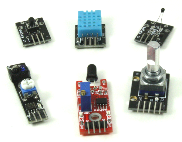
Figure 9-1. Different sensor module types and sizes
Over time it is easy to end up with a large collection of modules, some of which are more useful than others. I would suggest starting off with the largest kit of modules you can afford, and then figuring out which ones you use the most. Keep several of those on hand, and save the other less-used modules for a future project.
Warning
The descriptions found online for how various modules work are not always correct. It might be a translation issue, but sometimes an online description will state that a module will generate a high output when active, when in reality it will generate a low output. Always check the operation of a module with a digital multimeter (DMM) before committing it to a circuit. Most of the modules listed in this section have been tested to determine how they really work, and the descriptions here reflect those findings. That being said, I can’t claim that every module that may look like one of the modules listed in this chapter will behave the same or have the same pin functions. In this corner of the universe, standardization has yet to take hold.
As for schematics for the modules listed here, well, there really aren’t any official schematics that I have been able to locate. Several brave souls across the Internet have taken it upon themselves to trace out some of the module PCBs. I’ve attempted to gather what I could find and combine it with my own efforts at reverse engineering. In some cases the result is a complete schematic, and in others I just wanted to verify that the pins really did what the available (and rather minimal) documentation stated.
Physical Form Factors
Modules can vary in size from 1.8 by 1.5 cm (approx. 3/4 by 9/16 inch) to 4.2 by 1.7 cm (approx. 1 11/16 by 5/8 inch), with some as large as 3.4 by 2.5 cm (approx. 1 5/16 by 1 inch) for a 5V modular relay. Figure 9-2 shows a variety of module dimensions. Note that these are approximate dimensions. The actual PCB dimensions may vary by about +/– 1 mm (0.04 inches), depending on where the modules were produced.
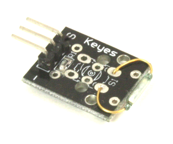
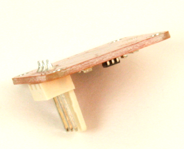
Many modules have mounting holes in the PCB large enough for a #2 machine screw. The metric equivalent is typically an M1.6 or M1.8 size. Figure 9-3 shows a stack of two modules made using 2-56 machine screws and nylon spacers. This happens to be a one-wire temperature sensor with a mercury tilt switch module.
Unfortunately, not all modules will stack nicely. Sometimes the mounting holes don’t have the same spacing, or they might be in the wrong places on the PCB to allow modules to stack. Some modules don’t have mounting holes at all, so always check before assuming that you will be able to create a stack of modules.
Interfaces
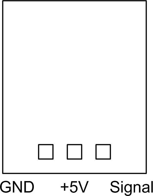
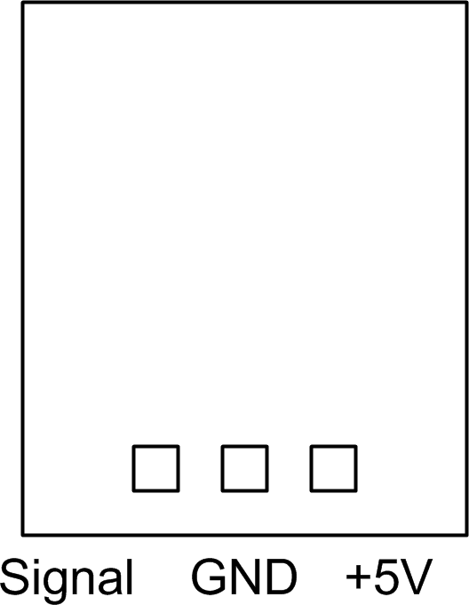
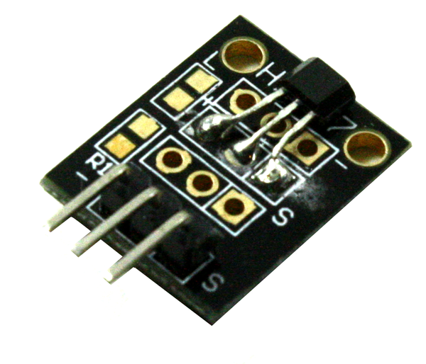
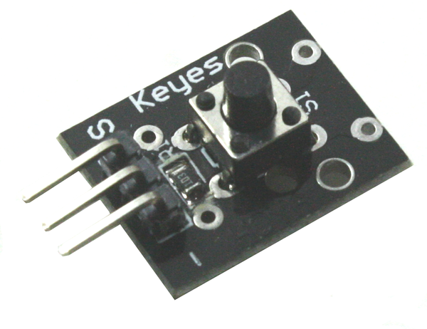
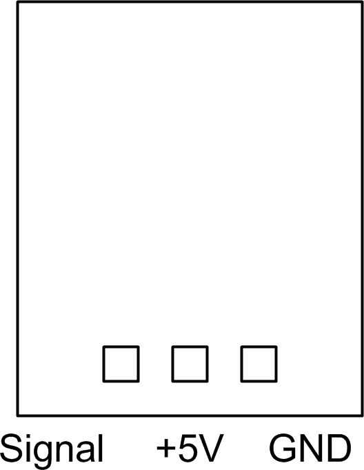
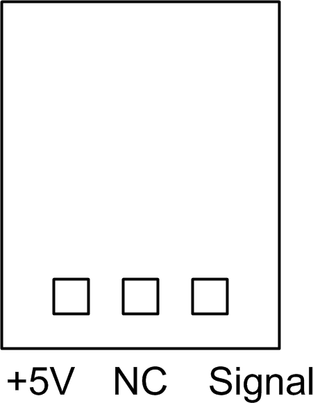
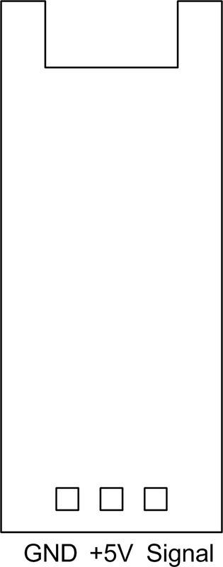
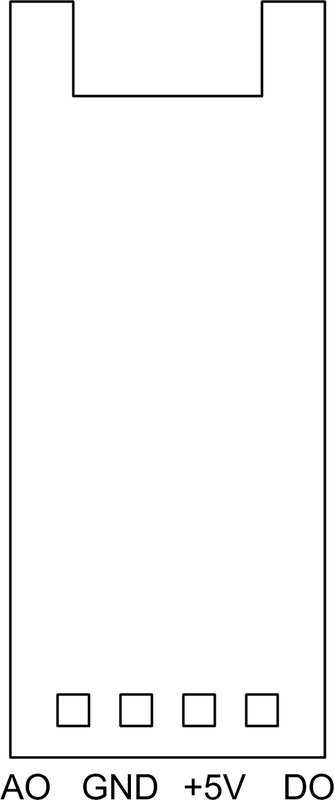
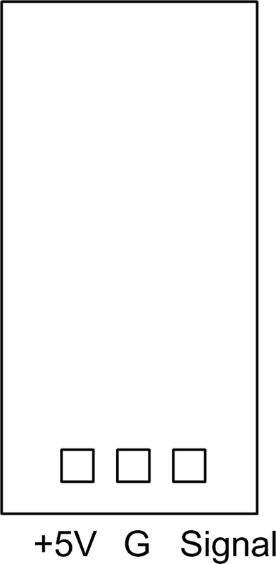
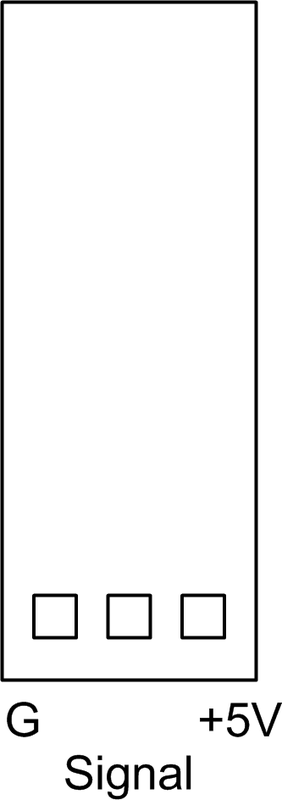
The pinouts used with the various PCB modules can vary from one type to another, so other than the TinkerKit series there really isn’t a lot of standardization. Figure 9-4 shows some of the variations you can expect to encounter.
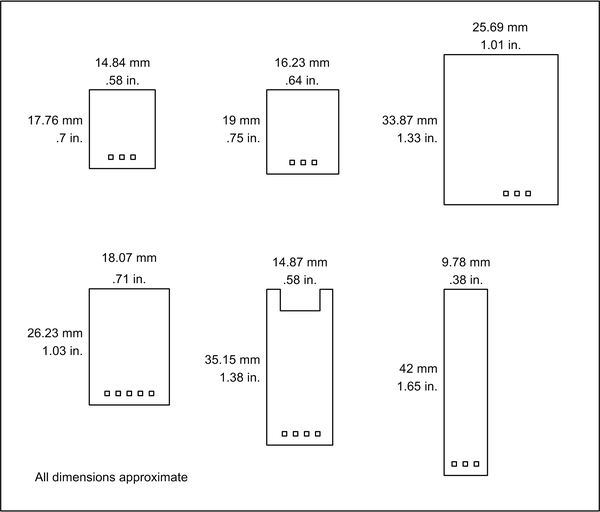
Figure 9-2. Examples of commonly encountered module dimensions
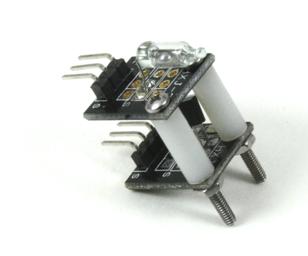
Figure 9-3. Modules mounted using #2 machine screws and spacers
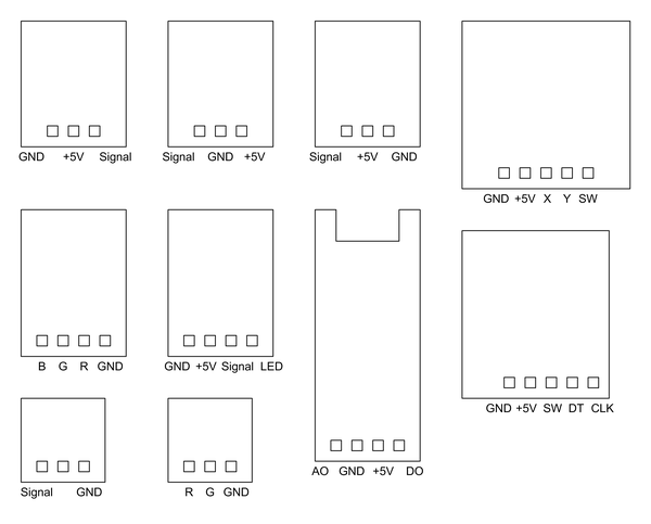
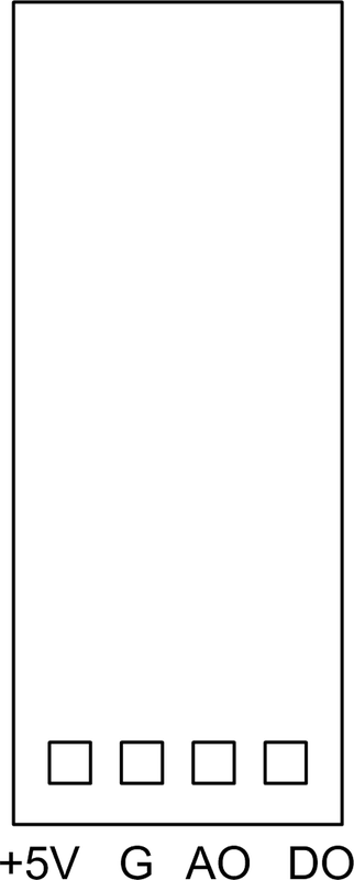
Figure 9-4. Typical pinout configurations used with modules
Note
Although you might assume that modules with three or four pins would be compatible with I/O extension shields that feature modular connectors or I/O pins arranged in blocks (such as those described in Chapter 8), that is not always the case. Pin-to-pin compatibility between modules and shields is only guaranteed when connecting a family of modules to an interface shield designed to work with those components. TinkerKit is one example of this, but only when connecting TinkerKit modules to a TinkerKit interface extender shield. Always check the module pins to verify the voltage and signal positions before connecting a module.
Because the AVR is a rather robust device it is possible to connect many sensors directly to the inputs of an Arduino, and some output devices as well. Power-hungry output devices, like a solid-state laser or an RGB LED, really need some type of driver to boost the current beyond what the AVR chip on an Arduino can supply directly (recall the current source and current sink specifications given in Chapter 3).
Some output modules have a high current interface built in, but some do not. A simple circuit, like the one shown in Figure 9-5, can be used to safely boost the current supplied to something like a relay or laser LED module. The value of R in the righthand circuit in Figure 9-5 would be determined by the LED and the amount of current it needs to operate. So long as the current doesn’t exceed the rating of the transistor it should work fine.
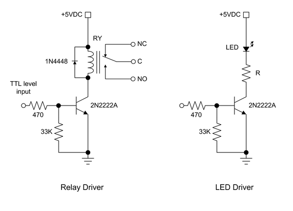
Figure 9-5. Output circuit for driving high-current devices
Another option is a special-purpose IC like the MAX4896, shown in Figure 9-6. It uses an SPI interface, and an Arduino can interface directly to the IC. While intended to drive small relays, this IC can handle large LEDs just as easily.
Module Sources
Single-PCB modules and kits of sensors with 24, 36, or more modules are available from the sources listed in Table 9-1. They can also be found on eBay and Amazon. Figure 9-7 shows a plastic storage container with a full suite of modules (37 different types; the last bin contains two different modules).
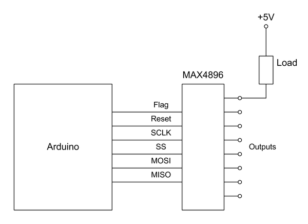
Figure 9-6. Output driver IC for multiple relays or other loads
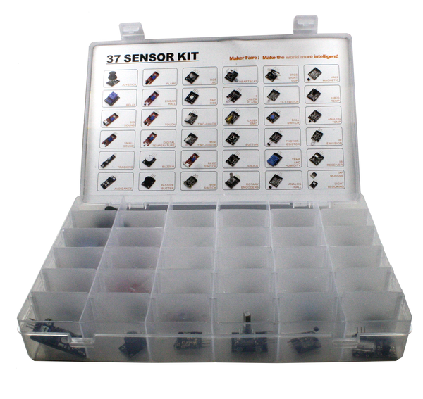
Figure 9-7. A set of input/output modules
Most of the suppliers listed in Table 9-1 also sell individual modules, as well as jumper wires, interconnection cables, and “bare” input and output components. You can buy most any module you might need in small quantities, although not every module in a kit may be available as a single item.
| Name | URL |
|---|---|
Adafruit |
|
CuteDigi |
|
DealeXtreme (DX) |
|
KEYES |
|
SainSmart |
|
Seeed Studio |
|
TinyCircuits |
|
Trossen Robotics |
|
Vetco |
Module Descriptions
This section lists modules from three sources: KEYES, SainSmart, and TinkerKit. The descriptions are, by necessity, terse. The main emphasis here is on the physical form and the electrical connections of the modules listed in the tables. “Sensors” describes the sensor components in more detail, and the modules are cross-referenced to the detailed descriptions where appropriate.
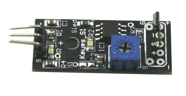
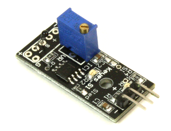
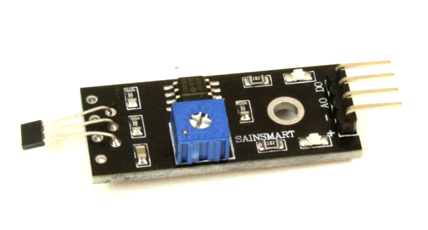
After working with various modules for a time you may notice that many of the modules described here use the same basic circuit. This typically consists of an LM393 comparator and some type of sensor. In each case a potentiometer sets the threshold comparison voltage, and the output of the LM393 is wired to the signal pin of the module. The KEYES modules with similar circuits are listed in Table 9-2, and the SainSmart modules with similar circuits are listed in Table 9-3.
| Part no. | Name |
|---|---|
Reed Switch Module |
|
Flame Sensor |
|
Conductive Contact Sensor |
|
Sensitive Microphone Sensor |
|
Microphone Sensor |
| Part no. | Name |
|---|---|
Photosensitive Sensor |
|
Vibration/Shock Sensor |
|
Hall Effect Sensor |
|
Flame Sensor |
Figure 9-8 shows a generic schematic representation of the LM393 comparator circuit used in the modules listed in Table 9-2 and Table 9-3. The actual component values may vary somewhat, but this same basic circuit is used in multiple modules. The sensor (IR flame, microphone, LDR, etc.) is the major difference between the modules.
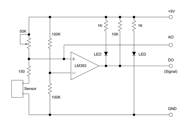
Figure 9-8. Generic module circuit with comparator IC
The DO (digital output) terminal comes directly from the comparator. It is high when the noninverting (+) input is greater than the inverting (–) input. The output of the comparator will go low if the noninverting input is lower than the inverting input. Some modules may be designed with the inputs to the comparator IC arranged opposite to what it shown in Figure 9-8, but the operating principle is the same.
The voltage on the noninverting input is set by the potentiometer, or pot. It is one-half of a voltage divider, with the sensor and perhaps a current-limiting resistor making up the other half. A second voltage divider is used to apply about one-half of the +5V VCC to the inverting input, or about 2.5V. This is the reference input. The pot is used to set the voltage at which the comparator will change its output as the sensor changes its resistance in response to some type of input.
On the output end of the circuit a 10K resistor is used as a pull-up on the output pin of the IC. The AO (analog output) is the “raw” value from the sensor at the input of the LM393 IC (in this case). On those modules with just a single output, only the output of the comparator is brought out to a terminal pin as the DO signal. A module may also have an LED to indicate when power is present, and some have an additional LED to indicate when the comparator output is low (it becomes a current sink for the LED).
How all this relates to a sensor depends on how the sensor responds to input, and you may need to experiment with it a bit to get a feel for how it behaves. In many cases an active sensor will exhibit decreased resistance, which will cause the noninverting input to go below the reference voltage on the inverting input. When this happens the output of the comparator circuit shown in Figure 9-8 will go low, and the LED on the output of the IC will be active (the IC serves as a current sink for the LED).
Comparator circuits that exhibit a low output when the input is in an active state or below some threshold are called active-low circuits. In these circuits, a low voltage on the output is equivalent to a true condition. Circuits that exhibit a high output level when the sensor is active or the input is above some threshold level are called active-high circuits. In an active-high circuit a high output is equivalent to a true condition. True and false in this sense just mean that the sensor is either receiving input or not, respectively.
Warning
Spend a few moments with a DMM (digital multimeter) and a magnifying glass or loupe and carefully examine a module before connecting it to an Arduino. This is particularly important with the bargain modules, where I have discovered missing parts, solder bridges (shorts) between pads, and connection pins that go nowhere. One module I examined had a factory-installed piece of wire soldered between traces connected to the +5V and ground pins! That would have caused some problems. Just because a module has pins for ground, +5V, and signal doesn’t mean that all the pins are actually used, or even that the pins do what the assigned names imply. Once any issues are addressed, the modules tend to work just fine (they only have a small number of parts on them, after all). Keep notes and save yourself from headaches later on.
Many common modules designed by the Chinese company Shenzhen KEYES DIY Robot Co. Ltd. (also known simply as KEYES) can be found as single units or bundled into kits of modules, usually with 36 or so modules per kit. You may also encounter modules with the letters “HXJ” on them. They are functionally identical to the KEYES modules, but the PCB layout may be slightly different.
Table 9-4 is a summary list of the KEYES modules covered in this section, and Table 9-7 contains images, notes, and pinout diagrams, from KY-001 to KY-040. Some of the models shown are KEYES, and some are from other vendors but are otherwise identical (the HXJ units, for example). They all share the same pinout and functions, and often have the same name (KY-002, KY-027, and so on). Notice that there are no KY-007, KY-014, KY-029, or KY-030 modules. I have no idea why.
| Part no. | Name | Part no. | Name |
|---|---|---|---|
Temperature Sensor |
Mini Reed Switch |
||
Vibration Sensor |
Infrared Sensor/Receiver |
||
Hall Effect Magnetic Field Sensor |
2 Axis Joystick |
||
Pushbutton Switch |
Linear Hall Effect Sensor |
||
Infrared Emitter |
Reed Switch Module |
||
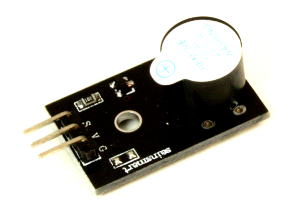
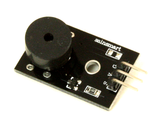
Passive Buzzer |
Flame Sensor |
||
Laser LED |
Magic Light Cup Module |
||
RGB Color LED |
Temperature Sensor |
||
Optical Interrupter |
Shock Sensor |
||
2 Color LED |
IR Proximity Sensor |
||
Active Buzzer |
IR Line Following Sensor |
||
Analog Temperature Sensor |
Automatic Flashing Color LED |
||
Temperature and Humidity Sensor |
Hall Effect Magnetic Sensor |
||
3 Color RGB LED |
Touch Sensor |
||
Mercury Tilt Switch |
Sensitive Microphone Sensor |
||
LDR Module |
Microphone Sensor |
||
5V Relay |
LED Heartbeat Sensor |
||
Tilt Switch |
Rotary Encoder |
SainSmart is another manufacturer of sensor modules. Table 9-5 is a summary of what is available in a SainSmart module kit, and Table 9-8 contains images, notes, and pinout diagrams. This is a representative list, as the contents of the kits can vary. The modules with a SainSmart Part no. are also available individually, and some of them are unique.
| Part no. | Name |
|---|---|
Part no. |
Name |
Relay Module |
|
Touch Sensor |
|
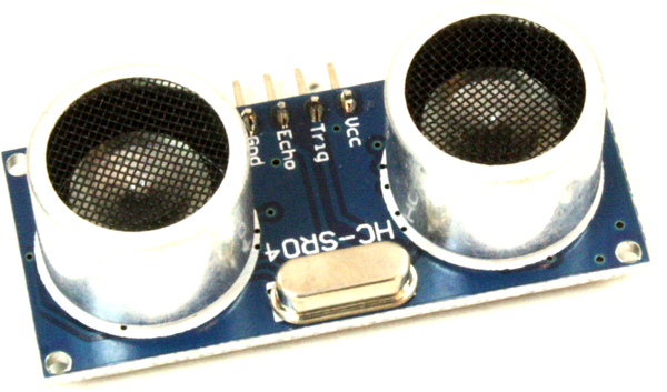
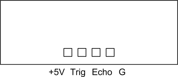
Ultrasonic Distance Sensor HC-SR04 |
|
Flame Sensor |
|
Temperature & Relative Humidity Sensor |
|
Active Buzzer |
|
Vibration/Shock Sensor |
|
Passive Buzzer |
|
Tracking Sensor |
|
Hall Effect Sensor |
|
Photosensitive Sensor |
|
Infrared Receiver |
|
Joystick Module |
|
Water Sensor |
Lastly, there are the TinkerKit modules. Table 9-6 is a summary listing, and Table 9-9 has details on each of the modules found in the “Pro” kit. The TinkerKit series of modules are designed to work with a TinkerKit interface shield (described in Chapter 8). Although the status of TinkerKit as a company is currently in limbo, the products are still available from Mouser, Newark/Element14, and other sources. Software libraries are available on GitHub. A set of basic datasheets for the modules are available from Mouser.
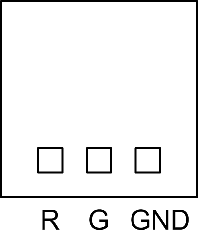
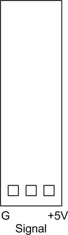
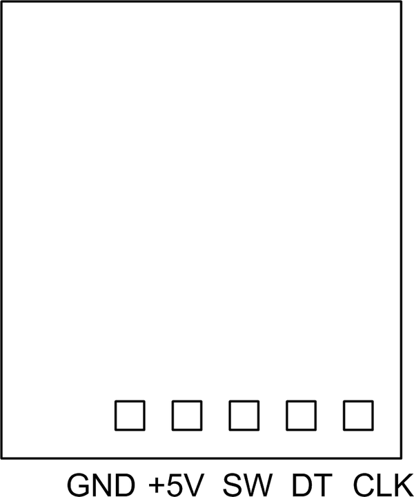
Table 9-9 doesn’t show pinout diagrams because the TinkerKit modules all use a standard pinout. The only difference between modules is between the discrete digital (on/off) and analog modules. Both types use the same basic connector pinout shown in Figure 9-9.
Circuitry on the TinkerKit modules handles the electrical interface, which might be level sensing, amplification, and so on. So bear in mind that with many of the TinkerKit modules the Arduino isn’t communicating directly with the sensor, LED, input control, or output device, but rather with an interface circuit. Flip a module over and check the back side to see what circuitry is installed. Even the LED modules have a driver transistor installed. The objective with the TinkerKit products was to create something that was easy to connect to an Arduino and relatively insensitive to minor errors, so some of the low-level interface interaction capability was given up to achieve that.
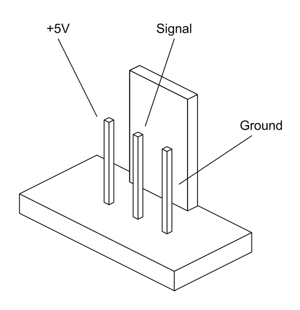
Figure 9-9. TinkerKit module common connector
| Part no. | Name | Part no. | Name |
|---|---|---|---|
Accelerometer Module |
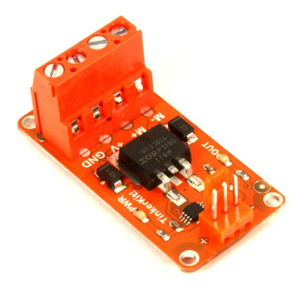
Mosfet Module |
||
Joystick Module |
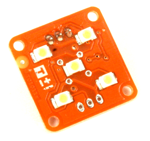
High Power LED Module |
||
Hall Effect Sensor |
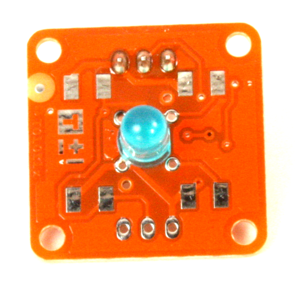
5 mm Blue LED Module |
||
LDR Module |
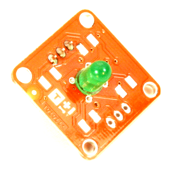
5 mm Green LED Module |
||
Rotary Potentiometer Module |
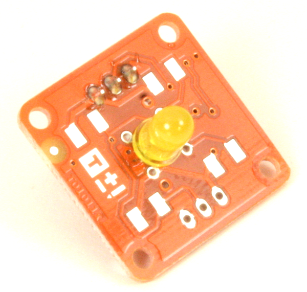
5 mm Yellow LED Module |
||
Linear Potentiometer Module |
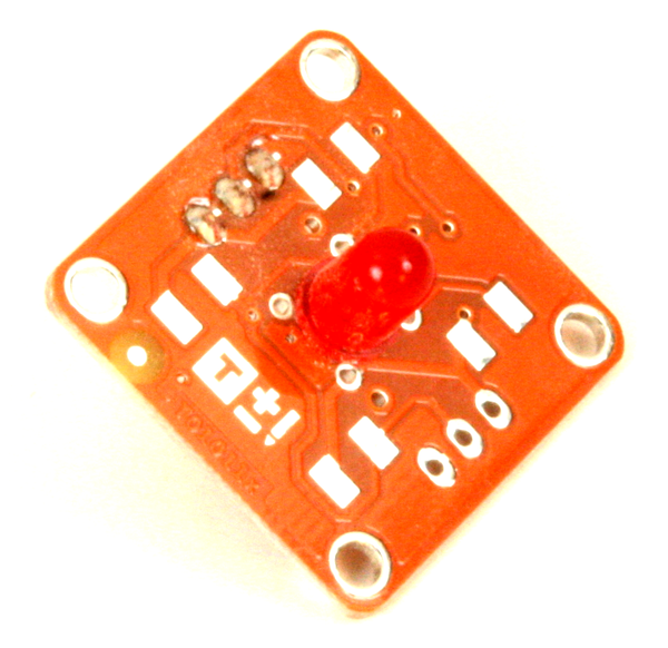
5 mm Red LED Module |
||
Pushbutton Module |
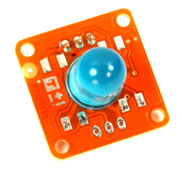
10 mm Blue LED Module |
||
Tilt Module |
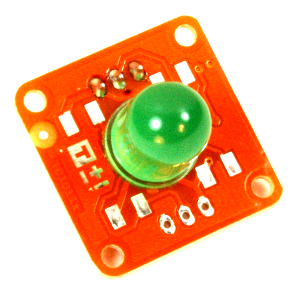
10 mm Green LED Module |
||
Thermistor Module |
10 mm Yellow LED Module |
||
Touch Sensor Module |
10 mm Red LED Module |
KEYES modules
| Part no. | Name and description | Image | Pinout |
|---|---|---|---|
Temperature Sensor |
|
|
|
Vibration Sensor |
|
|
|
Hall Effect Magnetic Field Sensor |
|
|
|
Pushbutton Switch |
|
|
|
Infrared Emitter |
|
|
|
Passive Buzzer |
|
|
|
Laser LED |
|
|
|
RGB 3-Color LED |
|
|
|
Optical Interrupter |
|
|
|
2 Color LED |
|
|
|
Active Buzzer |
|
|
|
Analog Temperature Sensor |
|
|
|
Temperature and Humidity Sensor |
|
|
|
3 Color RGB LED |
|
|
|
Mercury Tilt Switch |
|
|
|
LDR Module |
|
|
|
5V Relay |
|
|
|
Tilt Switch |
|
|
|
Mini Reed Switch |
|
|
|
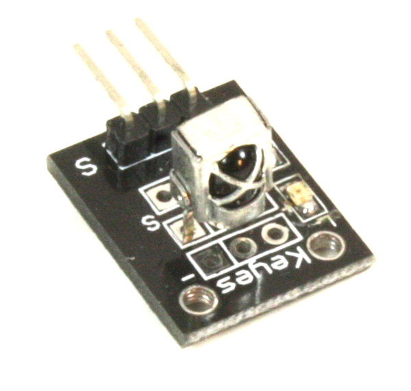
Infrared Sensor/Receiver |
|
|
|
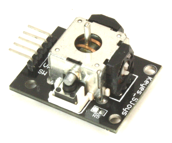
2 Axis Joystick |
|
|
|
Linear Hall Effect Sensor |
|
|
|
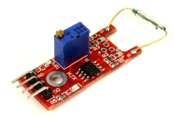
Reed Switch Module |
|
|
|
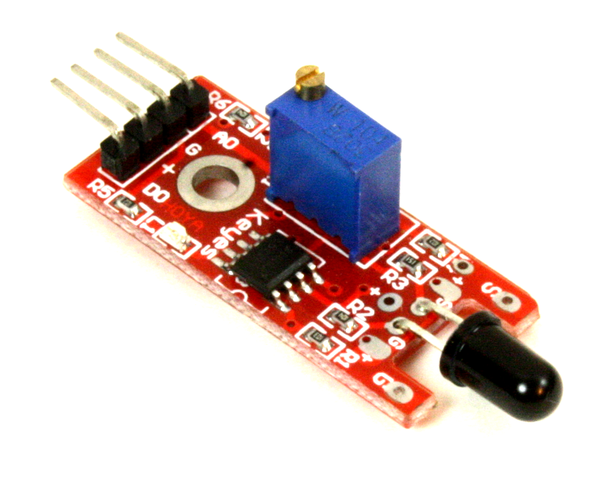
Flame Sensor |
|
|
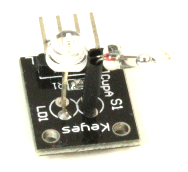
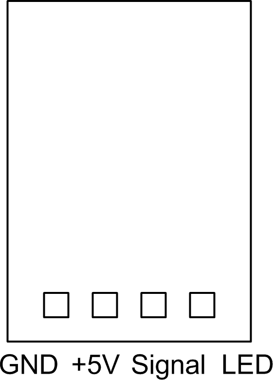
|
Magic Light Cup Module |
|
|
|
Temperature Sensor |
|
|
|
Shock (Impact) Sensor |
|
|
|
IR Proximity Sensor |
|
|
|
IR Line Following Sensor |
|
|
|
Automatic Flashing Color LED |
|
|
|
Hall Effect Magnetic Sensor |
|
|
|
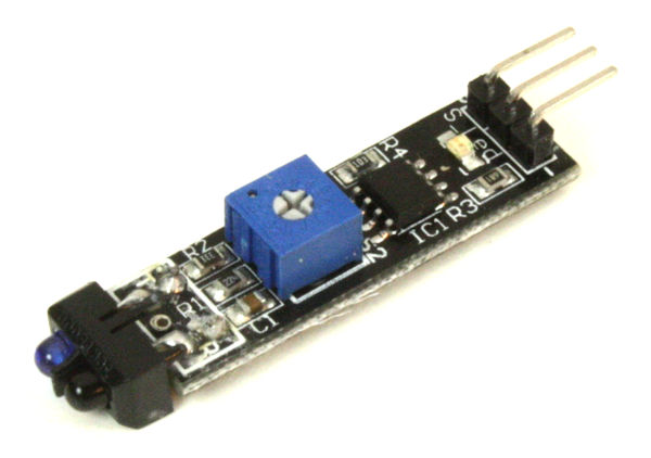
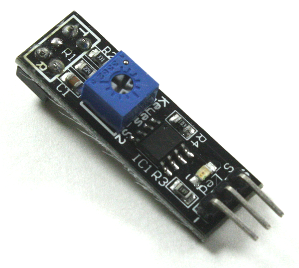
Conductive Contact Sensor |
|
|
|
Sensitive Microphone Sensor |
|
|
|
Microphone Sensor |
|
|
|
LED Heartbeat Sensor |
|
|
|
Rotary Encoder |
|
|
 ]
]


SainSmart modules
| Part no. | Name and description | Image | Pinout |
|---|---|---|---|
|
|
||
Ultrasonic Distance Sensor HC-SR04 |
|
|
|
Active Buzzer |
|
|
|
Passive Buzzer |
|
|
|
Hall Effect Sensor |
|
|
|
Infrared Receiver |
|
|
|
Water Sensor |
|
|
|
Touch Sensor |
|
|
|
Flame Sensor |
|
|
|
Temperature Sensor |
|
|
|
Temperature & Relative Humidity Sensor |
|
|
|
Vibration/Shock Sensor |
|
|
|
Tracking Sensor |
|
|
|
Photosensitive Sensor |
|
|
|
Joystick Module |
|
|
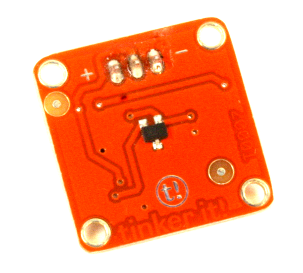
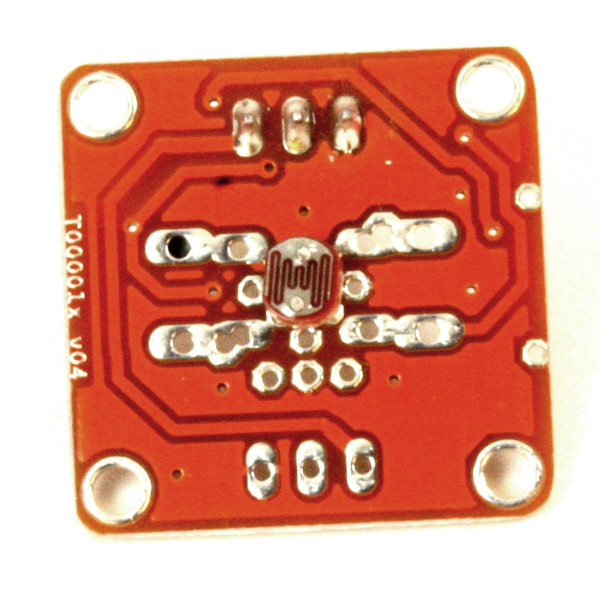
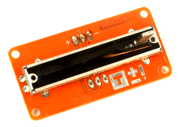
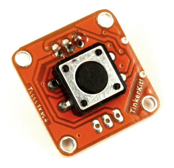
TinkerKit modules
| Part no. | Name and description | Image |
|---|---|---|
Accelerometer Module |
|
|
Joystick Module |
|
|
Hall Effect Sensor |
|
|
LDR Module |
|
|
Rotary Potentiometer Module |
|
|
Linear Potentiometer Module |
|
|
Pushbutton Module |
|
|
Tilt Module |
|
|
Thermistor Module |
|
|
Touch Sensor Module |
|
|
Relay Module |
|
|
Mosfet Module |
|
|
High Power LED Module |
|
|
5 mm Blue LED |
|
|
5 mm Green LED Module |
|
|
5 mm Yellow LED Module |
|
|
5 mm Red LED Module |
|
|
10 mm Blue LED Module |
|
|
10 mm Green LED Module |
|
|
10 mm Yellow LED Module |
|
|
10 mm Red LED Module |
|

Grove Modules
SeedStudio has amassed a large number of modules under the Grove interconnect system. Many of these are functionally similar to modules available from KEYES, SainSmart, and TinkerKit. Others are unique to the Grove product line.
The Grove modules are categorized into six groups: environment monitoring, motion sensing, user interface, physical monitoring, logic gate functions, and power control. The modules all use a standardized connection scheme involving a 4-pin modular connector with power, ground, and signal lines.
As with the TinkerKit modules, the advantage of the Grove modules is that you don’t have to try to verify (or figure out) what a module’s pins actually do. A shield that follows the Grove conventions (such as the Grove shields shown in Chapter 8) will connect to a Grove sensor or actuator module using a prefabricated cable. Seeed Studio also sells premade cables for connecting modules to an interface or control shield.
One feature of the Grove modules that I find appealing is the inclusion of mounting tabs in the PCB of most of the modules. This gets the mounting hardware out of the way of the circuitry (as opposed to mounting holes in the middle of the PCB layout) and the modular connectors are easy to use. An example Grove module is shown in Figure 9-10.
Figure 9-10. An example Grove module
At this time of writing, the TinkerKit modules appear to be fading, while the Grove modules appear to be very much alive and well. That’s not to say that TinkerKit won’t make a comeback, or that Grove will be around forever; things can and do change in the Arduino world on short time scales. As I pointed out earlier, this chapter and Chapter 8 are intended to provide examples of what is available, not serve as definitive references. The market is too volatile to allow for that.
If you are looking for modules that follow a convention of one sort or another, then I would recommend investigating the Grove products. If you want to use a different expansion or interface shield, you can create your own interface cables using readily available shells, pins, and sockets, as described in “Building Custom Connectors”. You can see a complete listing of the modules currently available at the Seeed Studio wiki.
Sensor and Module Descriptions
The remainder of this chapter describes some of the different types of Arduino-compatible components, modules, and sensors that are available. I say “some of” because, as with shields, new sensors and modules appear constantly, and some older types vanish if there isn’t enough of a market to justify continued production. Some modules are rather specialized one-off types, such as gas sensors or current monitors. Some sensors may disappear as they are replaced with newer types. You can find all the devices described here, and more, with very little effort using Google, browsing through the listings on Amazon.com, or checking the websites listed in “Sources”.
Table 9-10 lists the controls, sensors, actuators, displays, and modules described in this section. They are organized by function, class (input or output), and type (device, component, or module). Remember that the components on any module are also available as single items, so you can create your own module or incorporate the parts into something else.
| Function | Class | Type | Description |
|---|---|---|---|
Audio |
Output |
Device |
|
Audio |
Sensor |
Microphone |
|
Communication |
I/O |
Module |
|
Communication |
I/O |
Module |
|
Communication |
I/O |
Module |
|
Communication |
I/O |
Module |
|
Contact |
Sensor |
Switch |
|
Contact |
Output |
Switch |
|
Control |
Input |
Device |
|
Control |
Input |
Module |
|
Control |
Input |
Device |
|
Display |
Output |
Module |
|
Display |
Output |
Module |
|
Display |
Output |
Module |
|
Display |
Output |
Module |
|
Display |
Output |
Module |
|
Light emit |
Output |
Display |
|
Light emit |
Output |
Display |
|
Light emit |
Output |
Laser |
|
Light emit |
Output |
LED |
|
Light emit |
Output |
LED |
|
Light emit |
Output |
LED |
|
Light sense |
Sensor |
Photocell |
|
Light sense |
Sensor |
Diode |
|
Light sense |
Sensor |
Transistor |
|
IR sense |
Sensor |
IR |
|
Magnetic |
Sensor |
Solid state |
|
Magnetic |
Sensor |
Solid state |
|
Moisture |
Sensor |
PCB |
|
Motion |
Output |
Actuator |
|
Motion |
Output |
Actuator |
|
Motion |
Output |
Actuator |
|
Motion |
Sensor |
Solid state |
|
Motion |
Sensor |
Solid state |
|
Pressure |
Sensor |
Solid state |
|
Range |
Sensor |
Module |
|
Range |
Sensor |
Module |
|
Range |
Sensor |
Module |
|
Rotation |
Sensor |
Control |
|
Signal |
Output |
Module |
|
Temperature |
Sensor |
Solid state |
|
Temperature |
Sensor |
Module |
|
Temperature |
Sensor |
Module |
|
Tilt |
Sensor |
Switch |
|
Tilt |
Sensor |
Switch |
|
Time |
Support |
Module |
|
Time |
Support |
Module |
|
Time |
Support |
Module |
|
Time |
Support |
Module |
|
Voltage |
Output |
Module |
|
Water |
Sensor |
PCB |
Sensors
While it is possible to connect many sensors directly to an Arduino, modules like the ones listed in the previous section are definitely easier to deal with. But modules might not be a good choice if you want to create custom hardware for a specific application. In that case you will want to use just the sensor component and place it exactly where it needs to be.
A sensor is always an input device that acquires data from the physical environment and converts it into a form that a microcontroller can process. As the name implies, it senses something, where that something might be temperature, humidity, magnetic fields, visible light, heat, infrared, sound, or physical motion.
Temperature, Humidity, and Pressure Sensors
There are multiple choices available for environmental sensors that can be used with an Arduino. From simple continuity-based water detection sensors to sensitive temperature and humidity sensors, chances are there is a sensor that can measure how hot, how cold, how wet, or how dry the environment happens to be.
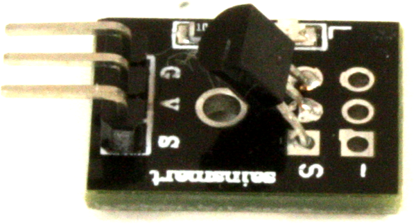
DS18B20
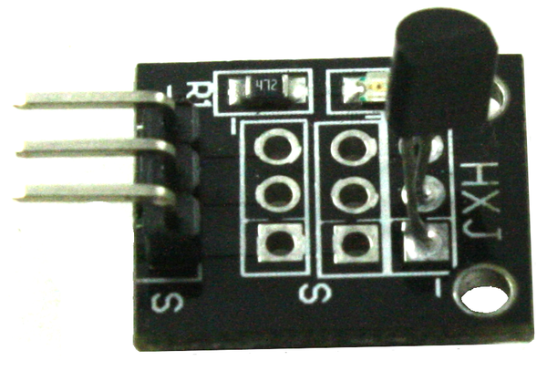
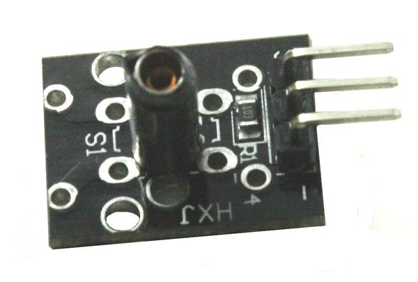
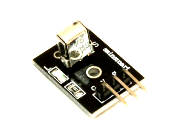
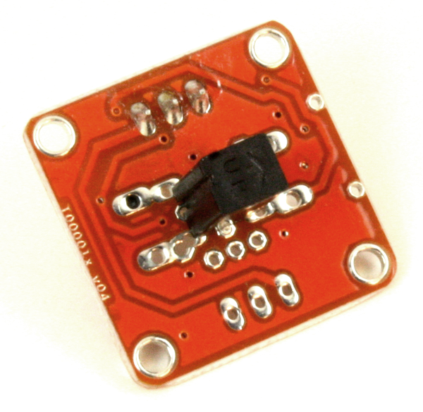
The DS18B20 is a so-called “one-wire” temperature sensor that returns a stream of binary data containing the current temperature at the sensor. Figure 9-11 shows a commonly available module with a DS18B20, some passive components, and an LED.
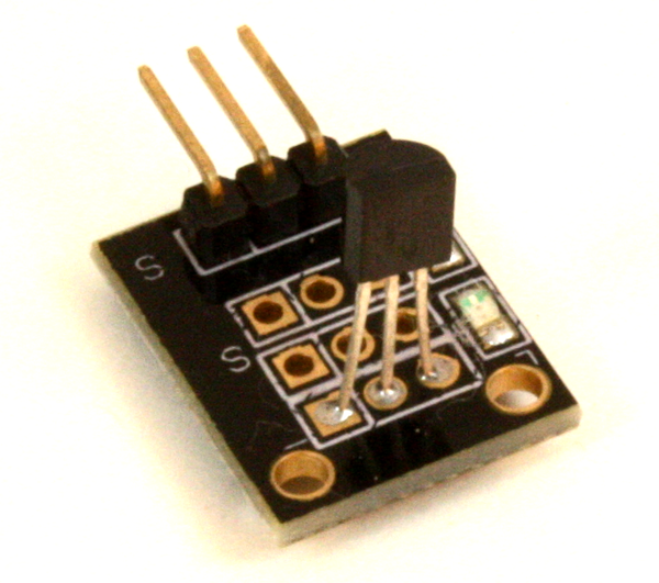
Figure 9-11. Typical DS18B20 module
Figure 9-12 shows the module mounted on a prototype shield along with a relay and a potentiometer. This, by the way, is a simple digital thermostat that was cobbled together to replace a dead bimetallic strip electromechanical thermostat in a small portable electric heater. The old-style mechanical thermostat never worked very well, but this simple digital replacement does an excellent job. The Arduino that it connects to also provides the ability to log temperature data and perform other functions. A cheap heater in the Internet of Things? Sure, why not?
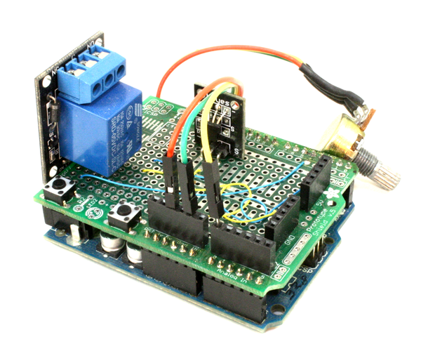
Figure 9-12. Example application of DS18B20 module
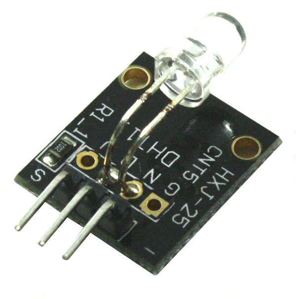
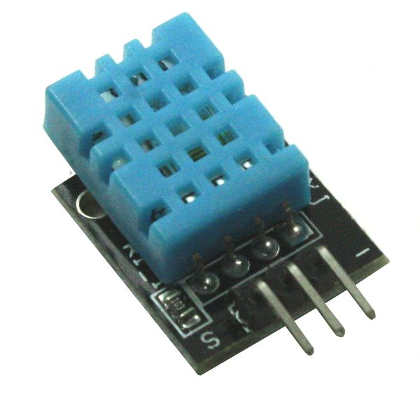
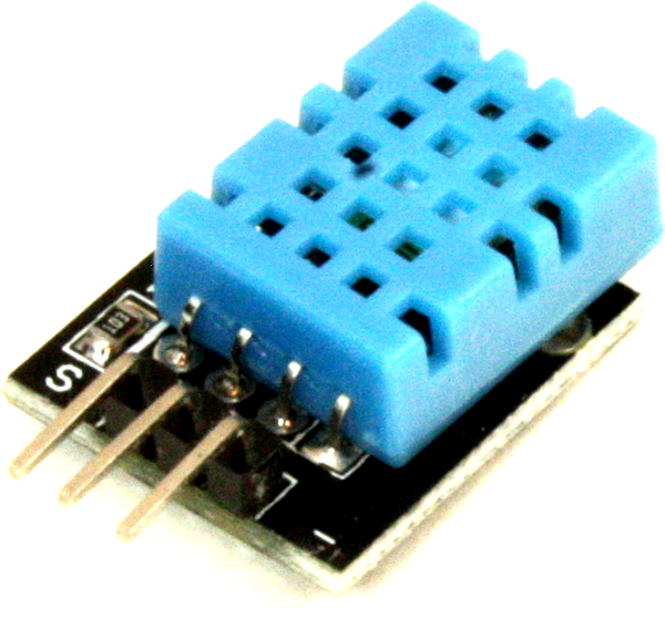
DHT11 and DHT22 sensors
The DHT11 and DHT22 temperature and humidity sensors come in three-terminal plastic packages, as shown in Figure 9-13. They can also be found already mounted on a small PCB, as shown in Figure 9-14.
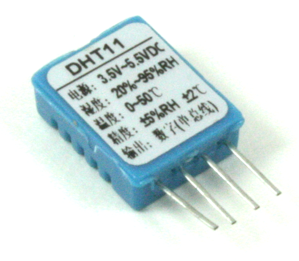
Figure 9-13. DHT11 package
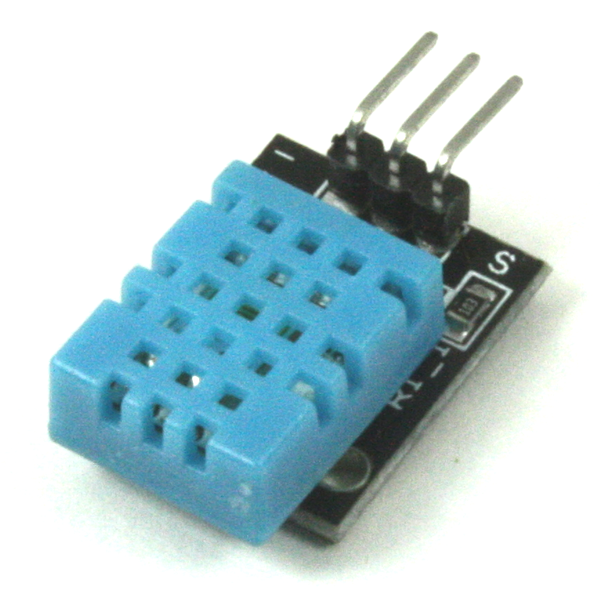
Figure 9-14. DHT11/DHT22 module
The DHT11 and DHT22 sensors differ in terms of resolution and serial data rate. The DHT11 is a basic device with a temperature sensing accuracy of +/– 2 degrees C, and a humidity resolution of +/– 5% relative humidity. It has a working range of 20 to 90% relative humidity, and 0 to 50 degrees C. The DHT22 features +/– 0.2 degrees C temperature resolution and +/– 1% RH sensing capability, and a faster serial data timing rate. The DHT22 has a wider sensing range than the DHT11: –40 to 80 degrees C and 0 to 100% RH. The pinout of the DHT22 is identical to the DHT11.
Both the DHT11 and DHT22 employ a nonstandard one-wire serial communications protocol. It works using a signal-response approach. The microcontroller pulls the single signal line low for a brief period of time, followed by allowing it to go high (via a pull-up resistor, either added externally or on the PCB module). The DHT11/DHT22 responds with 40 bits of serial data, organized as five 8-bit data values, including an 8-bit checksum.
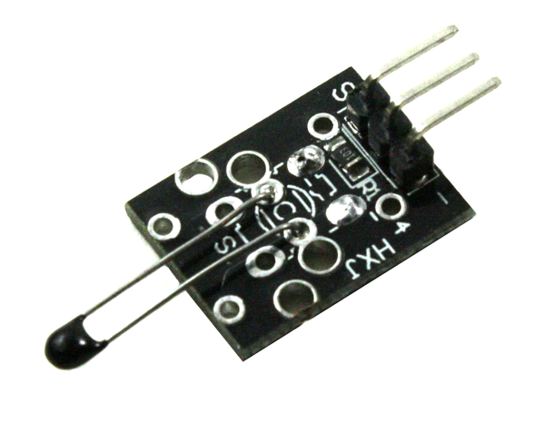
Thermistors
A thermistor is a temperature-controlled resistor. They are available with either a negative or positive temperature coefficient. A negative temperature coefficient (NTC) device will exhibit a lower resistance as the temperature increases. A positive temperature coefficient (PTC) device has the opposite behavior. NTC thermistors are the most common types found in sensor applications, and PTC types are often used as current inrush limiters.
Figure 9-15 shows one way to connect a thermistor to an Arduino, but be aware that the response curve of the thermistor is not linear. Some circuits replace the fixed resistor with a constant current source.
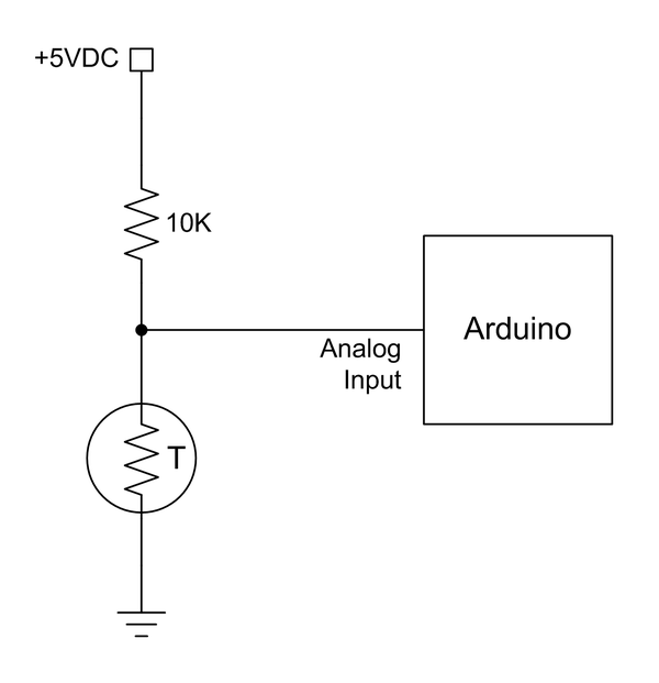
Figure 9-15. Simple thermistor connection to an Arduino
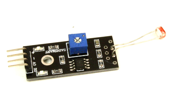
Although it is possible to connect a thermistor directly to an Arduino, an easier way is to use a module that includes the passive components necessary to create a voltage divider for the thermistor, such as the KY-028 shown in Table 9-7. You could also use the op amp circuit shown in Figure 9-26 to increase the sensitivity of the thermistor. Note that since most thermistors used for temperature sensing are NTC types, the voltage that appears on the analog input of the Arduino will drop as the temperature increases.
Water sensors
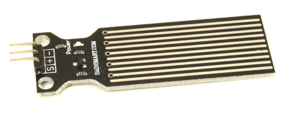
A water sensor is useful for many applications, from a flood sensor in a basement to a rain detector for an automated weather station. Table 9-8 shows one type of water detector available from SainSmart (the 20-011-946). This sensor incorporates an NPN transistor that will pull the output low when the thin traces on the PCB are connected by a water drop, or basically anything wet enough to cause the transistor to conduct.
Figure 9-16 shows the schematic for this sensor. As you can see, it’s not complicated, and could be used with just about any conductive wires or probes. Connect this circuit to a pair of steel wires, mount the wires so they are about 1/4 inch or so (or about a centimeter) above the basement floor, and it could be used to trigger an alarm upstairs when water starts to flood the basement.
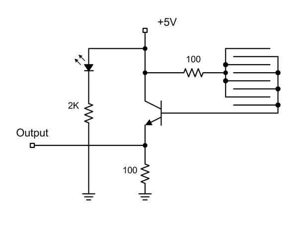
Figure 9-16. Water sensor schematic
Soil moisture sensors
In its simplest form a two-prong soil moisture sensor is really nothing more than a conductivity probe. The probe is configured to act as a component in a simple voltage divider, and the voltage that appears across it will be a function of the conductivity of the soil between the probes. You can purchase a kit consisting of a moisture probe, a small interface module, and a cable from suppliers like SainSmart. Figure 9-17 shows all three parts of such a kit.
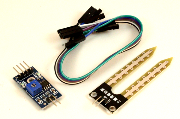
Figure 9-17. Soil moisture probe kit with interface module
The same effect could be achieved using almost any conductive material for the probes. For long-term use something like stainless steel or carbon rods might be a better choice where corrosion is a concern, and some type of amplifier or buffer is essential to get consistent readings without dumping a lot of current into the probe (which can cause some interesting side effects, and also help to corrode the probe’s electrodes).
Another variation on the soil moisture sensor, a Grove 101020008 from Seeed Studio, is shown in Figure 9-18. This sensor includes an on-board NPN transistor to boost the voltage drop to a level an Arduino AVR ADC can work with. The copper layer on the prongs of this probe have been plated with a thin layer of gold to help resist corrosion.
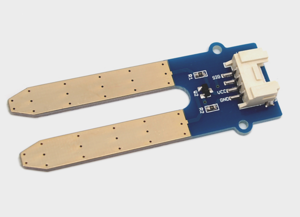
Figure 9-18. Self-contained soil moisture probe
The schematic for the self-contained moisture probe is shown in Figure 9-19. It is essentially the same as the circuit used with the water sensor, shown in Figure 9-16. Note that this design utilizes a four-terminal connector instead of the pin connections used on the probe in Figure 9-17. This is definitely more convenient, but pay attention to how the terminals in the connector are wired.
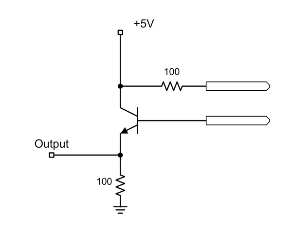
Figure 9-19. Self-contained soil moisture probe schematic
Barometric sensors
With a barometric pressure sensor, like the one shown in Figure 9-20, and the DHT11 or DHT22 modules described earlier (“DHT11 and DHT22 sensors”), an Arduino can be used to build a compact weather monitor. The sensor shown here is based on an MPL115A2 sensor with an I2C interface.
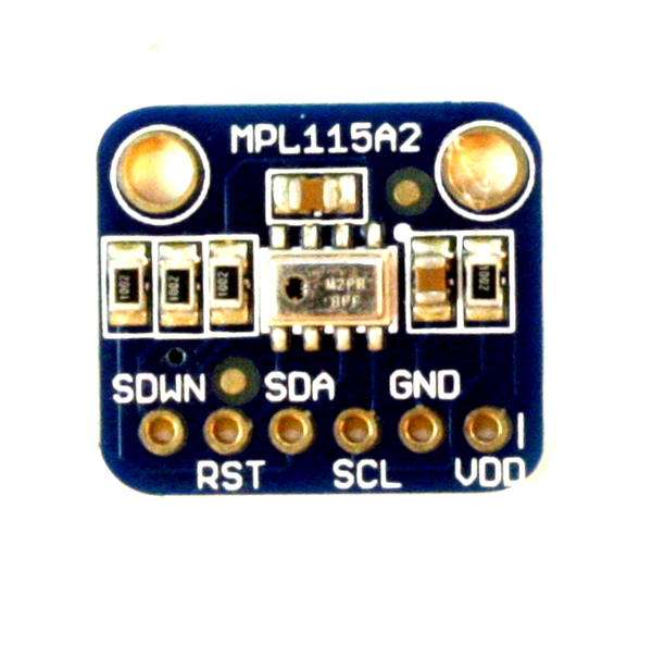
Figure 9-20. Barometric pressure sensor module
This particular module isn’t accurate enough to be used as an altimeter, but it’s fine for acquiring and logging weather data. Other modules based on sensors like the MPL3115A2 or BMP085 are accurate enough to be used as altimeters.
Tilt Sensors
A tilt sensor is typically nothing more than a small sealed capsule with a set of internal contacts and a small metal ball or bead of mercury inside. If the device is moved from its “neutral” orientation (perpendicular to the local gravitational pull), the ball or bead will move and close a circuit across the contacts. The operation is identical to closing a switch.
Bear in mind that a tilt sensor is not a proportional sensor. It is either tilted or not, so it is either open or closed electrically. There is nothing in between.
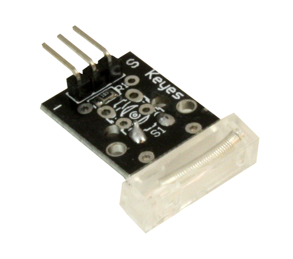
Single-axis tilt sensors
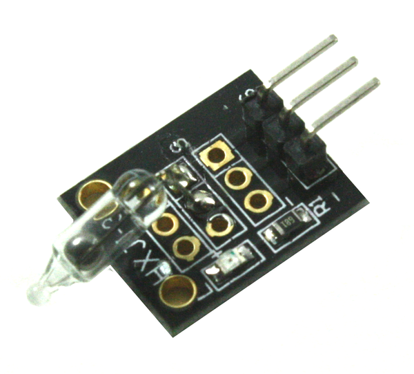
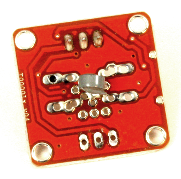
Figure 9-21 shows a module with a mercury bead tilt sensor, which happens to be a KY-017. This particular module will only sense tilt in one direction. You’ll need to use two or more of them to sense a tilt along either end of an axis.
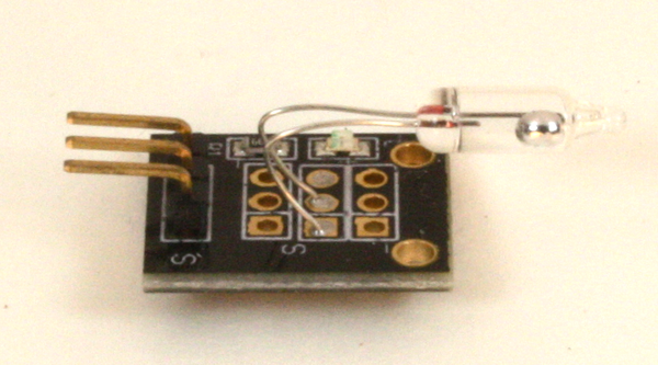
Figure 9-21. Single-axis tilt sensor
Dual-axis tilt sensors
The key to using a tilt sensor effectively is to determine the neutral position in a particular axis. Once this is known the sensor can be oriented to sense tilt along a particular horizontal axis. Figure 9-22 shows two tilt sensors on a single base to sense tilt in the x- and y-axes. Note that this arrangement will only sense tilt in one direction (either up or down, depending on how they are mounted).
If you want to sense up or down tilt in both axes, then four tilt sensors can be arranged at right angles to each other. This will detect tilt in both the +/– x and +/– y directions. Unlike a solid-state gyroscope (like those described in “Gyroscopes”), this type of circuit does not require a starting reference, and it will always work as long as there is gravity. The down side is that there is no in between: the tilt sensors are either on or off.
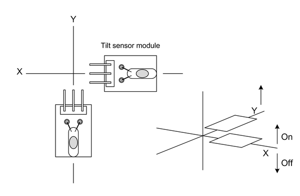
Figure 9-22. Dual-axis tilt sensor
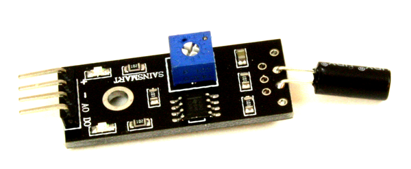
Audio Sensors
A microphone can be used in a number of interesting ways. One way is to incorporate the microphone as part of a security system to detect loud noises such as breaking glass, someone kicking in a door, or the sound of a gun being discharged. If it is sensitive enough it can even be used to detect footsteps.
A contact microphone can be used to collect diagnostic data from an internal combustion engine or even an electric motor while it is running. It is possible to detect noisy bearings and loose components this way. When combined with an optical sensor an omnidirectional microphone can be used to build a lightning range detector (the thunder arrives about 4 seconds after the flash for every mile of distance from the observer to the lightning bolt).
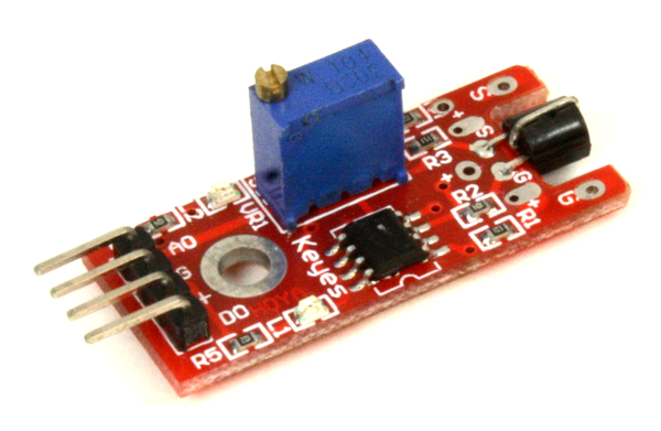
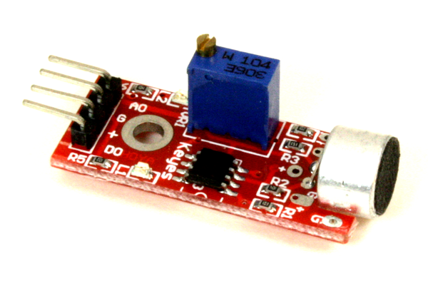
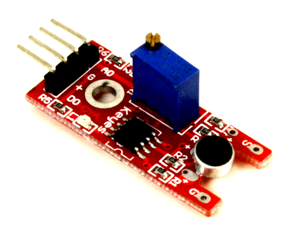
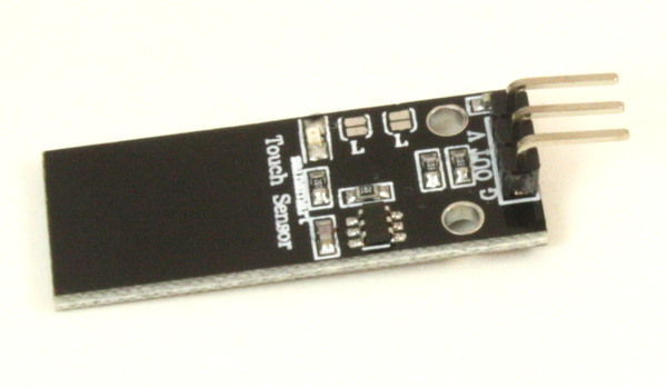
There are small modules available with microphones and an IC, like the one shown in Figure 9-23. The miniature potentiometer is used to set the trip threshold of the circuit. This module uses a circuit similar to the one shown in Figure 9-8.
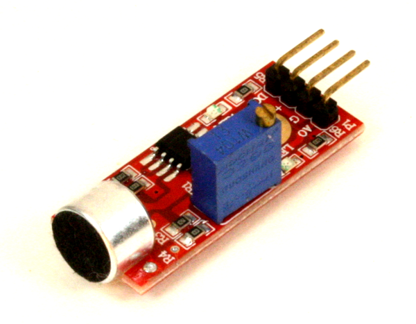
Figure 9-23. Audio pick-up module
It is also possible to connect a microphone directly to one of the analog inputs of an Arduino, although you wouldn’t have any control over the sensitivity. A simple op-amp circuit like the one shown in Figure 9-26 can be used to improve the sensitivity.
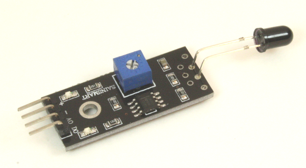
Light Sensors
Sensors for detecting light come in a variety of styles and types. Some, like infrared (IR) sensors, can detect heat; some respond to the IR emitted by flames, others respond to visible light. A light sensor may employ a resistive element that changes its intrinsic resistance in response to the amount of light that falls on it. Others employ a semiconductor for increased sensitivity and fast response.
Photocells
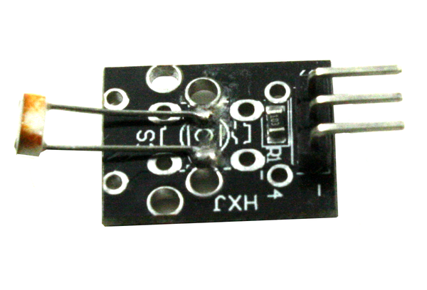
A photocell, also known as a light-dependent resistor (LDR), is exactly what the name implies: a component in which the resistance changes as a function of the amount of light impinging upon it. Most look like the one shown in Figure 9-24. While these devices aren’t all that fast by photodiode or phototransistor standards, they are still fast enough to carry audio in an amplitude-modulated beam of light. They are useful as ambient light level detectors, simple low-speed pulse-coded optical data links, beacon sensors for a robot so it can find a recharging station, and solar position trackers for a solar cell array.
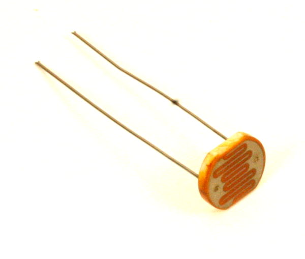
Figure 9-24. Typical low-cost LDR device
Photodiodes
Although most diodes have some degree of light sensitivity, a photodiode is built to enhance this effect. A photodiode is, as the name implies, a diode that has been manufactured such that it will go into conduction when light impinges on it, and a common type of photodiode is a PIN diode. The “I” stands for the layer of “intrinsic” silicon material between the P and N silicon parts of the diode, and that layer of intrinsic material makes a PIN diode a good light detector. Because they respond very quickly they are useful for optical data communications links and as position sensors for rotary mechanisms. PIN diodes are also found in high-frequency radio circuits, where they serve as switches. For more information about diodes and other solid-state devices, refer to the references listed in Appendix D.
Figure 9-25 shows how to connect a photodiode to an Arduino. Notice that the diode is reverse biased—in other words, it won’t normally conduct current until it is exposed to light. While this circuit will work with a sufficiently bright light source, it may struggle with low illumination levels.
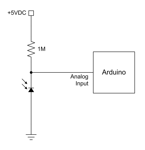
Figure 9-25. Simple photodiode connection to an Arduino
One way to improve the sensitivity is to use an op amp, as shown in Figure 9-26. In this case an LM358 op amp with a gain of up to around 10 is used to boost the small voltage change when the diode conducts to a level that the ADC in an Arduino can easily detect and convert. The trimmer potentiometer sets the gain of the circuit, so it can be adjusted to suit a particular application. This circuit can easily be assembled on a small solderless breadboard module, or the components can be mounted on a prototyping PCB (often called a “perf board”) for a more permanent arrangement.
You can browse the selection of photodiodes (and op amps) available from electronics distributors such as Digikey, Mouser, and Newark/Element14. Many surplus electronics suppliers also have stocks of photodiodes on hand.
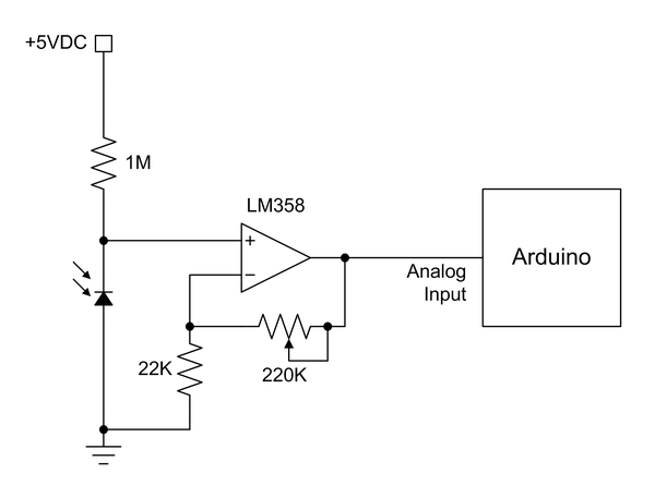
Figure 9-26. Photodiode connection with an op amp
Phototransistors
As the name implies, a phototransistor responds to light by varying the amount of current passing through the device, just as the base input lead would otherwise do. The circuit shown in Figure 9-8 will work with a phototransistor. Some modules, like the KY-039, simply bring out the transistor’s leads to the connector pins (you can clip off the LED and use the module as a phototransistor sensor module, by the way).
You can expand on the basic circuit by adding an op-amp for some gain. Figure 9-27 shows how this can be done. Just about any garden-variety NPN phototransistor will work, but I happen to like the BFH310, mainly because I got a great deal on a large bag of the things (check with an electronics distributor such as DigiKey or Mouser for availability).
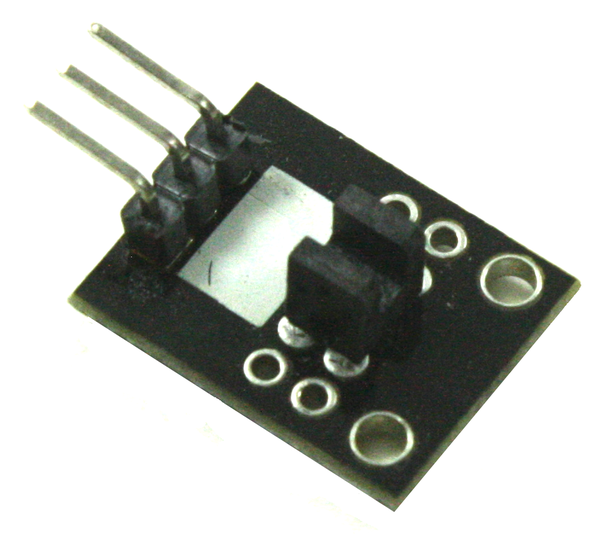
Common optical interrupters, like the one used in the KY-010 module, employ a phototransistor to sense the output of an LED. When something blocks the light by entering the gap in the component, the transistor will cease to conduct. Optical isolators (also called optocouplers or opto-isolators) also utilize an LED–phototransistor pair to couple a signal from one circuit to another without a direct electrical connection. You can build your own coupler with an LED, a phototransistor, and a section of black heat-shrink tubing to cover it all and keep out stray light.
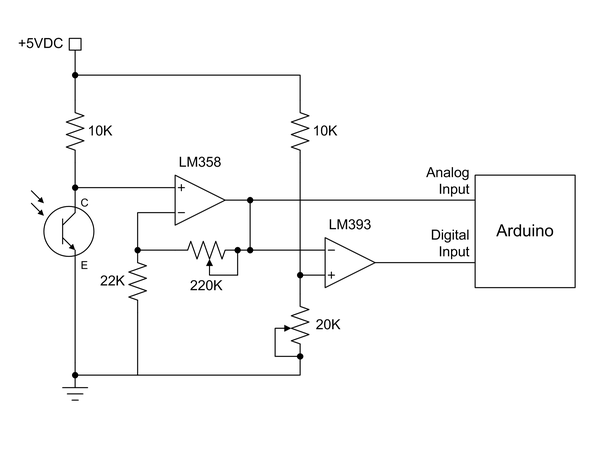
Figure 9-27. Phototransistor circuit with both analog and digital outputs
PIR sensors
A PIR (passive infrared) sensor measures the amount of infrared in its field of view. These are popular for security systems because they can usually detect very small changes in the ambient IR “glow” of a room. If the IR level deviates from the ambient baseline (such as when a warm human enters the room), the device will emit a signal. A PIR sensor can also be used to obtain a rough measurement of the temperature of whatever is in the field of view. Figure 9-28 shows a commonly available PIR module.
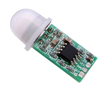
Figure 9-28. PIR detector
This module is available for around $2 from Banggood and other distributors. It uses three connections: +5V, ground, and output. The output goes high when the sensor detects a change in the ambient IR. Combine this and an audio sensor, like the one shown in Figure 9-23, with the basic security system code described in Example 5-5, and you’ll have a complete burglar alarm system.
Magnetic Sensors
One of the areas where semiconductor technology has made considerable strides is in the detection of static magnetic fields. Detecting an oscillating magnetic field, such as that produced by a coil, is relatively easy since all that is needed is another coil. Detecting a static magnetic field, such as that around a permanent magnet or the Earth’s magnetic field, is a bit more challenging. Prior to the development of electronic devices magnetic field sensors often incorporated magnets, coils, mirrors, and other components. A standard camping compass is an example of old-style technology, and it works fine for a hiking trip or for detecting the magnetic field around a wire carrying a continuous direct current, but collecting data from it is rather tedious. These days you can build a magnetic field detector or an electronic compass with no moving parts that will interface directly with a microcontroller.
Hall effect sensors
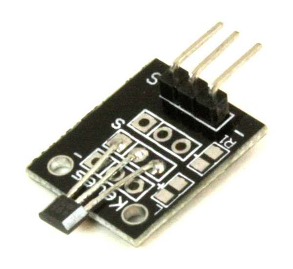
A Hall effect sensor can detect the presence of a magnetic field. Some types, like the A3144 used in the KY-003, are designed to be on/off-type devices: there either is or is not a magnetic field present. Other types, like the SS49E, are linear types, with an analog output proportional to the sensed magnetic field. The KY-024 is an example of a module with a linear Hall effect sensor.
Both the A3144 and the SS49E look like small plastic body transistors, so I won’t show them here. In the case of the A3144 and similar devices, you can connect it directly to an Arduino, which is essentially what the KY-003 module does. The KY-024 module uses the common comparator circuit shown in Figure 9-8.
Magnetometer sensors
Another form of magnetic sensor that can be useful with an Arduino is a compass, like the one shown in Figure 9-29. This unit from Adafruit uses an HMC5883L three-axis magnetometer. It features an I2C interface.
Vibration and Shock Sensors
Vibration and shock sensors are usually based on the detection of movement in a sensing mass of some sort. The sensing mass can be as simple as a mechanical arm with a small mass on the end and some contacts arranged so that the arm will close a circuit with one or the other as it deflects. Another variation might use an optical sensor that will change its output state when the arm breaks a beam of light. It might also be a spring-loaded sliding mass with contacts, optical sensors, or even a magnetic sensor. One type that is also used employs a piezo-electric sensor to detect movement in a sensing mass.
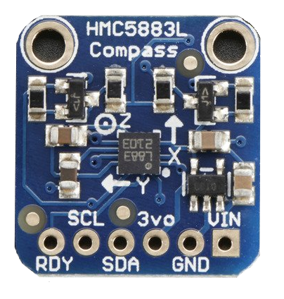
Figure 9-29. Magnetometer compass module
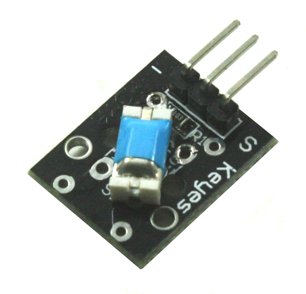
A very inexpensive type of vibration sensor uses a small conductive mass in a sealed enclosure. When the mass moves it will break and make contact with conductive sleeves at each end of the enclosure. The KY-020 is a typical module with a sensor of this type.
A shock sensor is similar to a vibration sensor, but in some cases shock sensors are designed to respond to specific input force levels in terms of some multiple of g (1g = the force of gravity at Earth’s mean sea-level surface). The KY-031 is an example of a small low-cost shock sensor module.
You can build your own shock or impact sensor using a metal ball (a BB works well), a spring (perhaps from a ballpoint pen), a short section of plastic tubing, and some fine-gauge wire. Figure 9-30 shows how all the parts are assembled.
If you need more precision, industrial-grade shock sensors are available that are calibrated to specific force levels. These are used for things like automobile impact testing and testing the impact tolerance of shipping cases for delicate devices. They aren’t cheap, however.
Motion Sensors
The ability to sense angular changes in position at varying rates is key to keeping things stable in three-dimensional space. Many quadcopters (or drones, as they are sometimes called) incorporate some form of multiaxis motion sensing to simulate the operation of a true mechanical gyroscope or inertial management unit (IMU). These types of devices are also popular with RC airplane and helicopter enthusiasts, and some adventurous souls have even incorporated them into model rockets to track and log the motion of the rocket during powered flight.
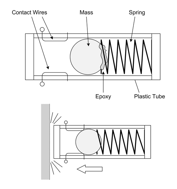
Figure 9-30. A homemade impact or shock sensor
Recent advances in technology and manufacturing techniques have driven down the prices of these devices to previously unimaginable levels. A solid-state rate gyroscope or accelerometer that once cost upwards of $50 can now be had for around $10. With the low cost, and the fact that the IC components are very small surface-mount packages with fine pitch leads, it makes more sense to buy a module rather than attempt to assemble something from scratch—unless, of course, you want to use it as part of something larger and you have the ability to deal with surface-mount parts.
Gyroscopes
The term “gyroscope,” or “gyro,” is something of a misnomer when applied to digital sensing devices. Unlike true mechanical gyroscopes, these devices are more like angular rate sensors intended to sense motion around an axis. They don’t inherently reference an inertial starting position like a true gyroscope. An IMU can do that, but most electromechanical IMU devices are large, heavy things with three (or more) internal high-speed gyroscopes in precision ball-bearing gimbal mounts along with electric motors and position sensors. They also tend to be very, very expensive. However, with some clever programming and the use of multiaxis accelerometers (discussed next) it is possible to simulate an IMU. Figure 9-31 shows a three-axis rate gyro module, available from DealeXtreme, Banggood, and other suppliers.
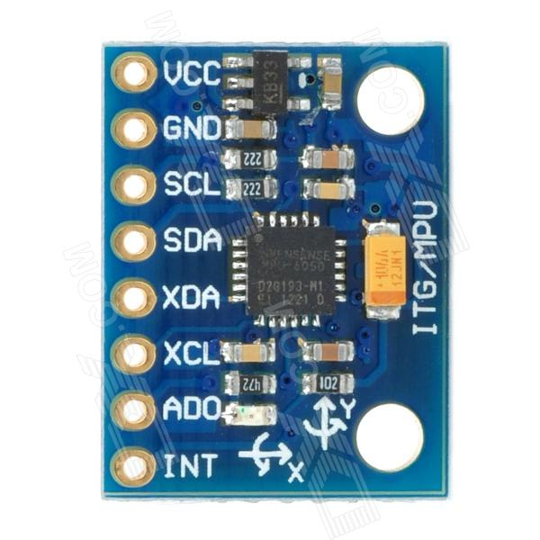
Figure 9-31. Three-axis rate gyroscope module
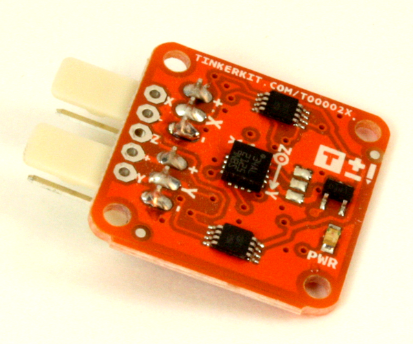
Accelerometers
An accelerometer senses a change in velocity along a particular linear axis. When the accelerometer is moving at a constant velocity it will not detect any change, but when the velocity changes due to either acceleration or deceleration, the sensor will generate an output. A three-axis accelerometer arrangement will detect velocity changes in the x-, y-, and z-axes. Figure 9-32 shows an inexpensive MMA7361-based single-axis accelerometer module from DealeXtreme, but modules like this can also be obtained from Adafruit, SparkFun, and other suppliers.
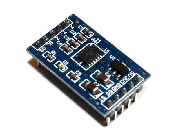
Figure 9-32. Accelerometer module
Contact and Position Sensors
Contact sensors are found in all manner of applications, from beverage bottling machines to computer-controlled tools in a machine shop. The heavy-duty pushbutton on an effects box like those used by musicians is a type of contact sensor. But regardless of how they are made, contact sensors all work on the same principle: either they are in physical contact with something, or they are not.
Position sensors, as the name implies, are used to sense the position of something. Unlike a contact sensor, a position sensor will usually have the ability to sense the degree of closeness or some amount of angular rotation. Some position sensors employ reflected light, others utilize sound, and still others incorporate a specially designed rotor and a light beam to measure angular motion. One other form of position sensor, called an absolute encoder, uses an internal glass disk with very fine marks to determine the precise degree of rotation of a shaft. Absolute encoders aren’t covered here.
Contact switches
A contact switch can be as simple as a wire “whisker” made from a spring with a conductive post through the center, like those found on the little robotic bugs sold as children’s toys. When the whisker is bent it causes the spring to make contact with the conductive post and closes the circuit. In other words, it’s just a switch. Figure 9-33 shows a close-up view of this type of contact sensor.
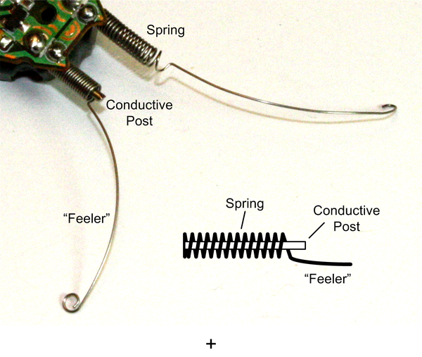
Figure 9-33. Spring and whisker contact sensor
At the other end of the spectrum are so-called snap-action switches like the one shown mounted on a module in Figure 9-34. This happens to be a Meeeno crash sensor module. These types of switches are often found in applications such as limit sensors for robotics or computer-numeric controlled (CNC) machine tools.
A pushbutton switch can also serve as a contact sensor. The old-style push switches used in automobiles to turn on the interior light when the door is opened make excellent contact sensors (although they might require a fair amount of force to activate them—more than the typical little robot can deliver). Even a copper strip and a screw can be used to sense physical contact, as shown in Figure 9-35. The main thing is that the switch closes (or opens, as the case may be) the circuit, which an Arduino can sense and then respond to.
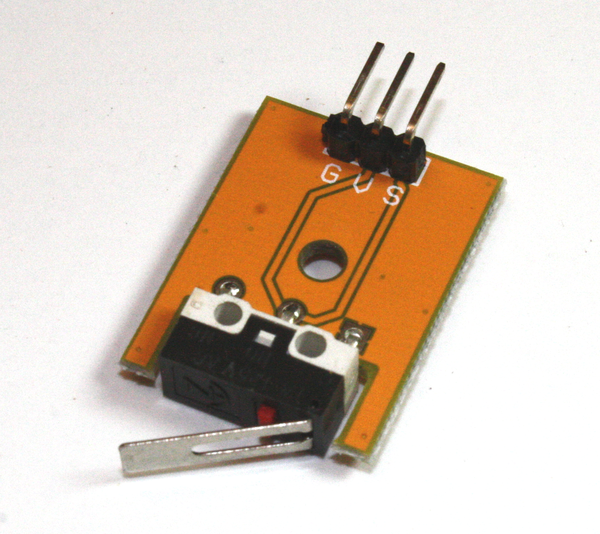
Figure 9-34. Typical snap-action switch
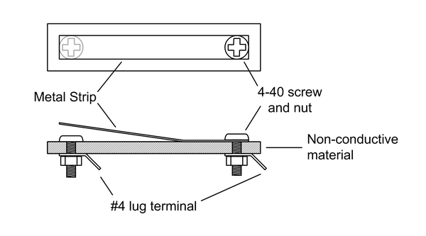
Figure 9-35. Simple contact sensor made from a metal strip
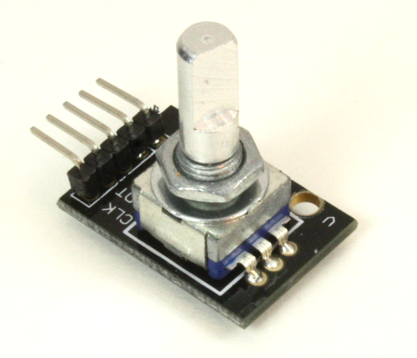
Digital rotary encoders
A digital rotary encoder, like the units shown in Figure 9-36, will generate pulses or emit a numeric value as a shaft is rotated. The KY-040 module also uses a rotary encoder. Some rotary encoders have detents on the shaft so that the operator will feel slight bumps as the shaft is turned. For applications that don’t involve someone turning a knob, the shaft just moves freely and continuously. See Chapter 12 for an example of how to create software to read a rotary encoder like the KY-040.
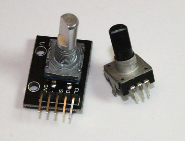
Figure 9-36. Digital rotary encoders
Old-style computer mice used a coated metal ball instead of an LED, and two rotary encoders to detect the motion of the ball. These are becoming scarce, but they have some interesting parts inside. If you take one apart you can see the plastic wheels with evenly spaced slots. As the wheels move, the beam of light from an LED is interrupted. By sensing the timing of the pulses the small microcontroller in the mouse could generate numeric values indicating how far the mouse had moved in the x and y directions across a surface. Figure 9-37 shows the insides of a typical ball mouse.
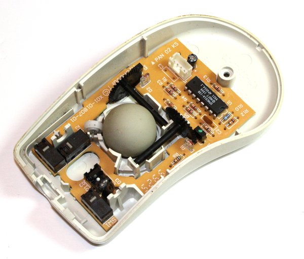
Figure 9-37. Old-style mouse with a ball and rotary encoders
In this particular mouse the LED sender and phototransistor (or photodiode, perhaps) are two separate components. Other models of these old ball mice use optical interrupter components, like those used on the KY-010 module shown in Table 9-7. The interrupt wheels are driven by shafts that contact the sides of the metal ball. If you’ve ever used a ball mouse for any period of time you know that you must occasionally remove the ball and clean any accumulated stuff from the shafts (and the ball, as well). You can remove the interrupter wheels and the optical sensors and reuse them in something else—frankly, the interrupter wheels are probably the most useful parts in a ball mouse.
Laser transmitter/receivers
The module shown in Figure 9-38 is a short-range laser transmitter and receiver designed primarily for obstacle detection or any other task where reflectance can be used to sense an object. It could possibly be used as a data link, but the optics would need to be refined to achieve any significant range.
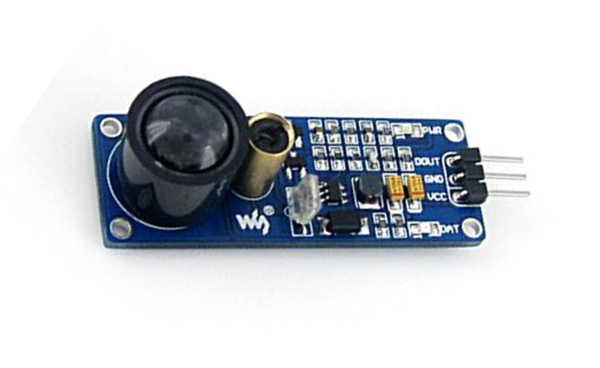
Figure 9-38. Short-range laser object detector
Range Sensors
The ability to both detect an object and determine its distance from the sensor is a key function in many robotics applications. A range sensor typically employs reflection, be it of light, sound, or radio waves in the case of radar. We’ll cover light and sound here, as radar sensors tend to be rather pricey and work better over extended distances. For short-range sensing an optical or acoustic sensor works fine, and they’re very inexpensive.
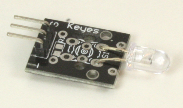
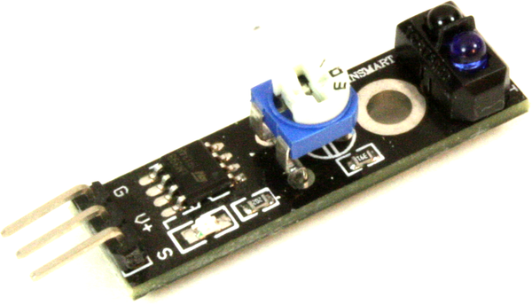
LED object sensors
An LED object sensor works by measuring the light from an LED (either optical or IR) reflected from a surface. These devices typically have an IR LED and a detector situated side-by-side, like the module shown in Figure 9-39. They don’t measure the travel time of the light from the emitter back to the sensor, because at short ranges the speed of light makes that extremely difficult to do. If you want to measure the distance from the Earth to the Moon using one of the retroreflectors left by the Apollo missions, then a pulsed laser, and a big telescope, and a good high-precision timer will do the job. But for an Arduino, a reflective sensor will serve to keep a small robot from colliding with a wall or allow it to follow a line on the floor.
Ultrasonic range finders
If you’re old enough, you might remember the old “instant” cameras that came with an ultrasonic range finder for automatic focusing and ejected a photograph that you could watch develop. The range finder typically consisted of a pair of piezoelectric sensors, one wired as an emitter and the other as a receiver. The emitter generated a short pulse of ultrasonic sound and the echo was detected by the receiver. With this kind of range finder, the time between the output of the pulse and the echo return is determined by the distance to whatever the sensors are pointing toward. This works because sound moves relatively slowly, so obtaining the time between the pulse and the return is not a particularly difficult thing to do with fast enough logic.
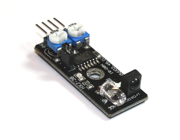
Figure 9-39. Reflective object sensor module
These days you can pick up an ultrasonic range finder for a few dollars that can be connected to an Arduino. An example of a readily available ultrasonic sensor is the 20-019-100 module shown in Table 9-8.
Communications
There are numerous modules for communications applications, ranging from plain RS-232 adapters to wireless communications and laser transmitter/receiver modules.
APC220 Wireless Modules
APC220 transceiver modules operate at 418 to 455 MHz. A complete digital link consists of two modules and an optional USB adapter. This allows for one module to be connected to a PC, and the other to be attached to an Arduino. The APC220 can transfer data at 19,200 bits per second with a range of up to 1,000 meters. The multifunction shield described in “Miscellaneous Shields” comes with a connection point for an APC220 module, as does the 16 × 2 LCD shield from DFRobot (also covered in Chapter 8). Figure 9-40 shows a pair of APC220 modules.
315/433 MHz RF Modules
With a range of up to 500 feet (150 meters) these modules are a low-cost alternative to the APC220. The downside is that they are not transceivers, but come as a set consisting of a transmitter and a receiver as shown in Figure 9-41. They are available preset to either 315 MHz or 433 MHz. Note that you will need to add your own antenna.
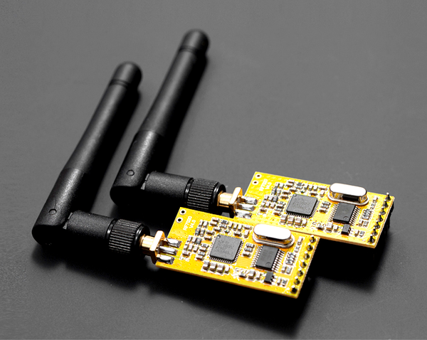
Figure 9-40. APC220 RF transceiver modules (image source: DFRobot)
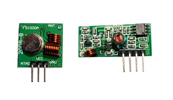
Figure 9-41. 433 MHz transmitter and receiver
ESP8266 Transceiver
This highly integrated WiFi module, shown in Figure 9-42, supports the 802.11 b/g/n protocols and uses a serial interface to communicate with an Arduino. The on-board 32-bit MCU has a TCP/IP network protocol stack in its firmware. It handles the low-level details of establishing and maintaining a digital link, so all the Arduino needs to do is specify an address to connect with, or wait for some other module to connect with it.
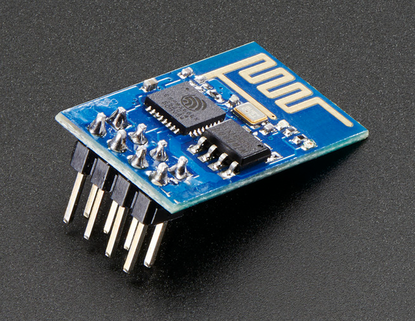
Figure 9-42. WiFi transceiver module
NRF24L01
The NRF24L01 module, shown in Figure 9-43, is a low-power transceiver operating at 2.4 GHz with about an 800 foot (250 meter) range. It uses an SPI interface to communicate with an Arduino. These modules can be purchased for around $3 from multiple sources.
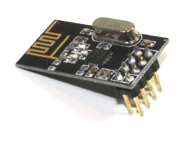
Figure 9-43. NRF24L01 RF transceiver
RS-232 adapter
The AVR MCU devices used in Arduino boards have a built-in UART (or USART, if you want to follow Atmel’s terminology), but it doesn’t generate standard RS-232 signals. Rather than build a custom converter, an RS-232 adapter module provides the converter, IC, and a DB-9 connector, as shown in Figure 9-44. The RxD and TxD pins from the MCU connect directly to the module.
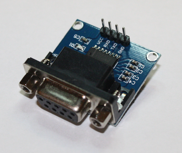
Figure 9-44. RS-232 adapter module
Output Devices and Components
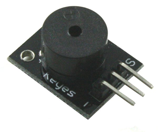
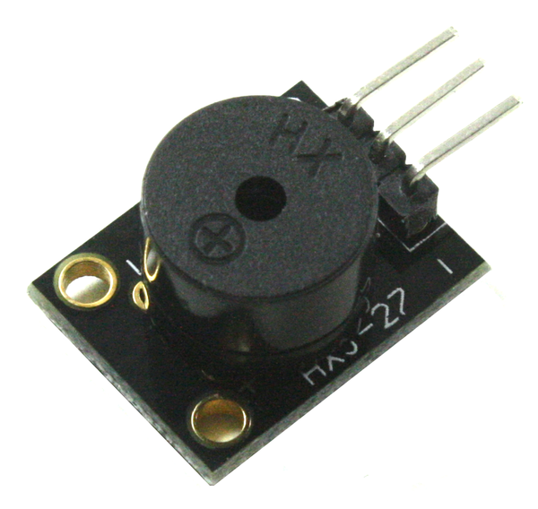
An output from an Arduino can be an LED, a servo motor, a relay, or some other module, component, or device that responds to a signal or command from the AVR microcontroller on an Arduino. This section starts with light sources, followed by relays, motors, and servos. It also covers sound sources, like the KY-006 pulse-responsive speaker shown in Table 9-7. User input and output components are covered in later sections.
Light Sources
Light sources range from old-fashioned light bulbs in a wide range of sizes and types to LEDs, solid-state devices that act like diodes but emit a bright glow when current flows through them. We’ll focus on LEDs in this section, mainly because they’re inexpensive, they last a long time, and they don’t always need a driver circuit. Even a tiny incandescent light bulb can draw a significant amount of current, and they tend to burn out and can get hot. That being said, there’s no reason you can’t use incandescent bulbs; just be prepared for additional circuit complexity (and cost) and the need to occasionally replace a dead bulb.
LEDs come in a wide range of styles, sizes, and colors. An AVR microcontroller can supply the 5 to 10 mA necessary to operate an LED, but it is generally not a good idea to directly connect a lot of LEDs or attempt to drive something like a high-output LED module. For that, a driver of some sort is the best way to go. The following images show some of the types of LEDs that are available, and they can also be found already mounted on module PCBs, like those shown in Table 9-7 and Table 9-9.
Single-color LEDs
Single-color LEDs range in size from miniscule surface-mount components like the D13 LED on an Arduino board to the huge devices used for lighting and illumination applications. Figure 9-45 shows a selection of some of the various types available.
Bicolor LEDs
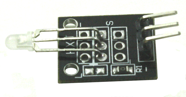
A bicolor LED is basically just two LEDs mounted in a single package, which generally looks like a regular LED with an internal connection arrangement like that shown in Figure 9-46. The internal LEDs are connected backward with respect to one another. When current flows in one direction one of the LEDs will glow, and when the current is reversed the other LED will glow.
Another available type of bicolor LED employs three leads. One lead is common; the other two each connect to one of the LED chips inside the device’s plastic package.
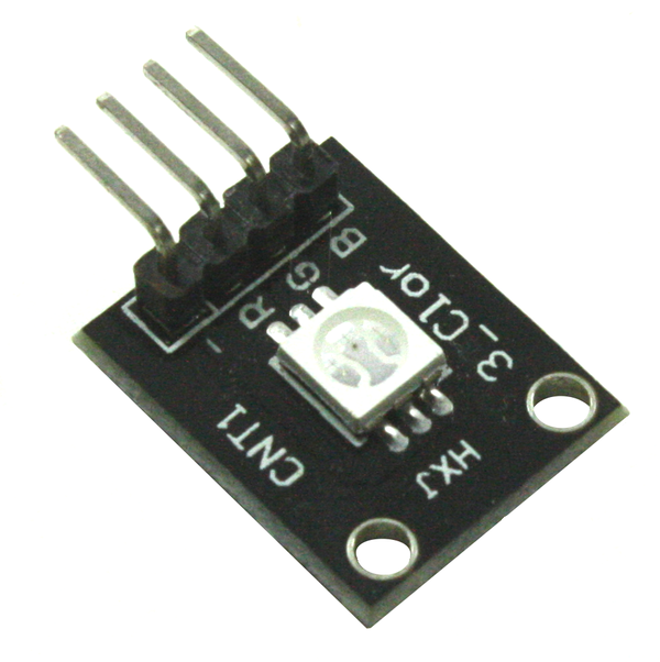
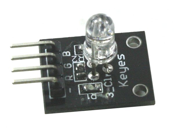
Tricolor (RGB) LEDs
A tricolor LED is comprised of three separate LED chips in a single molded plastic package. Figure 9-47 shows a surface-mount part. Large numbers of these can be mounted in an array on a single PCB, and multiple PCBs can be mounted side-by-side to create a large full-color LED display.
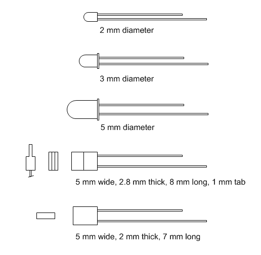
Figure 9-45. Common single-color LEDs
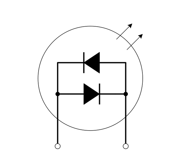
Figure 9-46. Two-lead bicolor LED internal connections
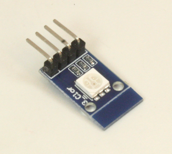
Figure 9-47. Surface-mount tri-color LED
A tricolor LED can produce an approximation of any visible color by varying the intensity of the output of each of the internal LEDs. Because the LED die (the individual LED chips) are physically separate, the colors are blended with a diffuser of some sort. From a distance it can look convincing. High-power, high-output RGB LEDs have been used to create huge color displays, like those seen on the sides of buildings or in large sports stadiums.
LED matrix
An LED matrix is useful for a variety of applications. An 8 × 8 matrix, like the one shown in Figure 9-48, can be used to display letters or numbers. If you arrange a lot of these modules side-by-side you can create a moving text display.
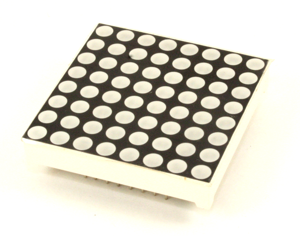
Figure 9-48. 8 × 8 LED matrix
Notice that the module is designed such that there is only a small amount of space at the side between the LED “pits” and the edge of the module. When these types of matrix modules are mounted side-by-side the gap between the last column or row on one module and the adjoining column or row on the next module is the same as the gap between the LEDs in the center of the module. This preserves the spacing when many modules are used to create large displays.
7-segment LED display
The venerable 7-segment display has been around for a long time. Other than single LEDs, this was the first viable application for LED technology, and by the late 1970s 7-segment and alphanumeric LED digit display modules were starting to show up in all types of applications. Figure 9-49 shows a typical four-digit display module.
As with the LED matrix module shown in Figure 9-48, the spacing gaps at the ends of this module are small so that multiple modules may be placed end-to-end. You could easily create a 12-digit floating-point display with three of these parts.
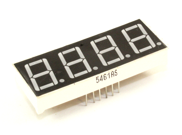
Figure 9-49. Typical 4-digit 7-segment display
7-segment LED modules
7-segment display modules are available with a built-in SPI or I2C interface. The module shown in Figure 9-50 is one such example. This particular module can be purchased from Tindie (see Table 9-11). There are also modules available with multiple displays, and they can be had in red, green, yellow, and blue.
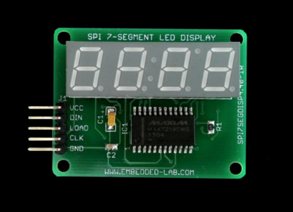
Figure 9-50. 7-segment display module with SPI interface
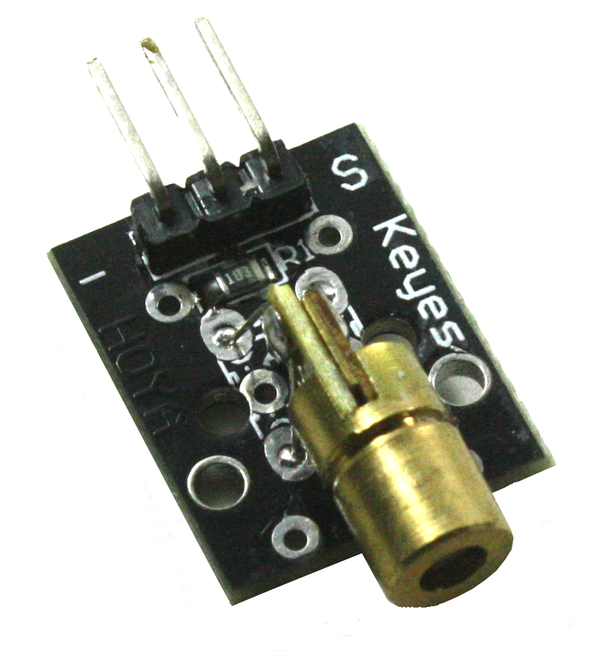
Lasers
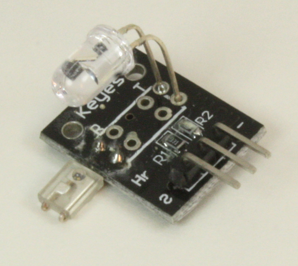
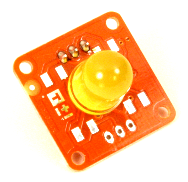
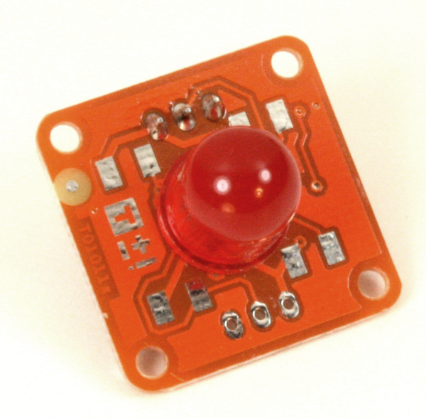
Some types of diode light sources are also lasers, like those found in laser pointers, while others are powerful enough to cut plastic or wood. A solid-state laser is essentially an LED with some internal tweaks to make it produce coherent light. Laser LEDs are available with output wavelengths ranging from infrared to blue. Without these devices things like laser levels for construction work, pointers for lecturers and instructors, surface profilers for 3D modeling, CD and DVD players and recorders, and some types of industrial cutting tools would not be possible. A typical small LED laser module is shown in Figure 9-51 (this is a KY-008). The laser LED can be purchased as a separate component from electronics distributors.
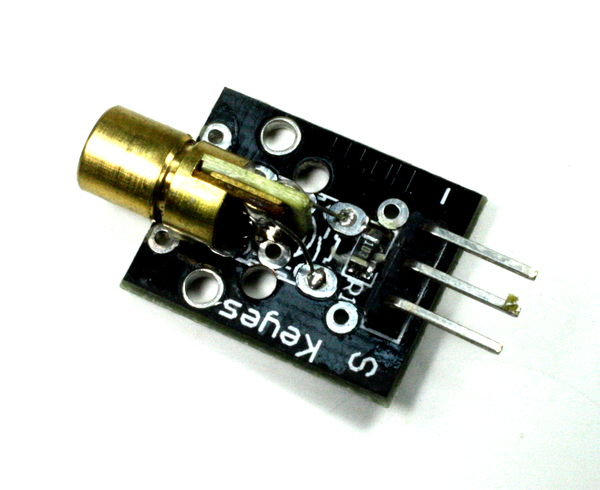
Figure 9-51. Typical low-power red LED laser
Relays, Motors, and Servos
Many small relays can draw more current to energize the internal coil than the AVR microcontroller on an Arduino PCB can safely deliver. Motors and servos are examples of very useful devices that often need a driver component of some sort to deliver the current they need to operate.
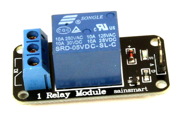
Relays
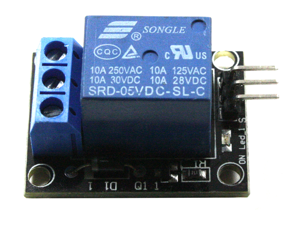
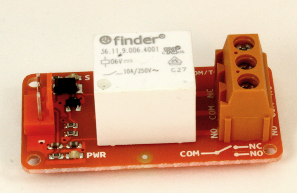
Relays come in a wide variety of sizes and shapes, ranging from small packages that look like a 14-pin DIP IC to huge things for controlling high-current loads in industrial equipment. For most Arduino applications a small relay is all that is needed. A small relay can operate a larger relay, which in turn can operate an even larger relay, and so on. The KY-019 is an example of a relay module that can be connected directly to an Arduino.
A relay driver can be as simple as a 2N2222 transistor, or it might be an IC designed specifically to deal with the current and reverse spikes encountered with relays. The circuit in Figure 9-5, shown earlier, uses an NPN transistor to control a small PCB-mounted relay.
Figure 9-52 shows a module with four relays. The PCB also includes the driver transistors, resistors, and diodes needed. All that is required is a source of 5V DC to drive the coils in the relays and standard logic signals to control them.
Servo control
The term servo typically refers to a small device something like a motor, although at one time it used to refer to large bulky actuators used for things like positioning guns on a naval vessel or performing analog calculations. Typical small servos, like the ones shown in Figure 9-53, are intended for use in radio-controlled cars and aircraft, as well as hobbyest robotics.
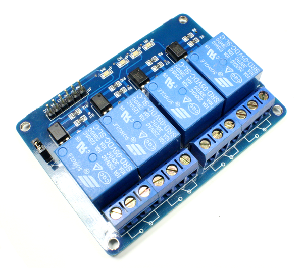
Figure 9-52. Relay module with four PCB-mounted relays
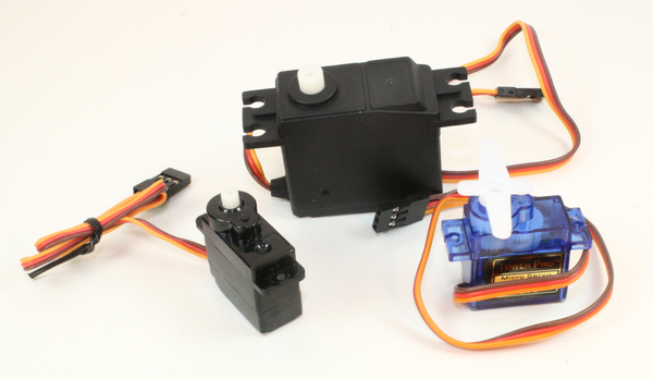
Figure 9-53. A selection of small servos
Although shields are available for use with servos (see Chapter 8), an AVR microcontroller can drive these devices directly with its PWM outputs. A servo like those in Figure 9-53 rotates a drive shaft through 180 degrees, with the amount of rotation determined by the pulse width and frequency of a control signal.
DC motor control
DC motors are commonly controlled with what is called an “H-bridge” circuit, and Figure 9-54 shows a simplified diagram. An H-bridge can be used with continuous DC or a PWM signal, and depending on how it is driven the motor can run in either forward or reverse.
I wouldn’t recommended building a motor control circuit from scratch (unless you really want to, of course). A shield like the one shown in Figure 9-55 has everything needed to control a DC motor. It also has a heat sink to dissipate the heat generated with high current loads. This particular shield is from Seeed Studio. Note that the shield will control two DC motors or one stepper motor.
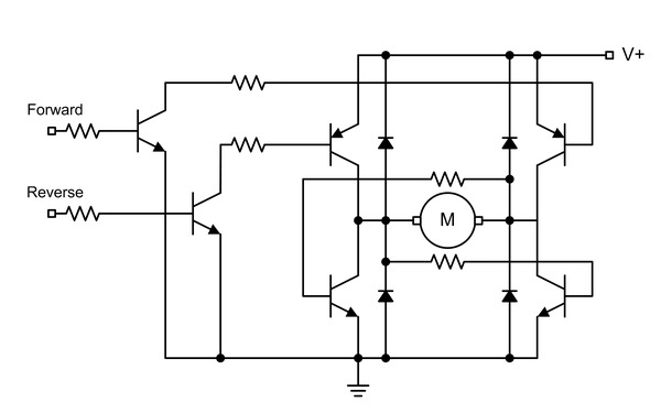
Figure 9-54. Simplified H-bridge
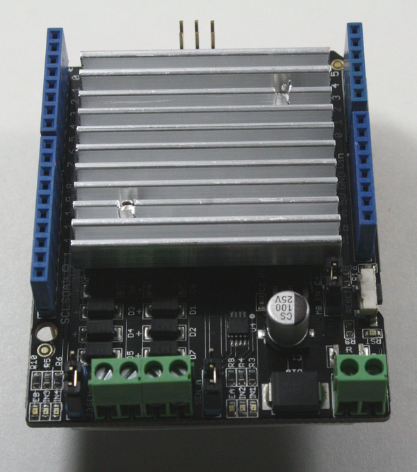
Figure 9-55. Motor control shield
Stepper motor control
Stepper motors are relatively simple to control, provided that the necessary electronics are in place to generate the pulses that will cause the motor shaft to rotate. One requirement is current, and while an IC like the ULN2003A provides everything necessary to drive a small stepper motor, it won’t handle large motors with high current demands. The ULN2003A is basically just an array of eight Darlington transistors, so the Arduino has to take care of all of the timing for the motor pulses.
There are shields available (see Chapter 8) that contain circuitry for one to four stepper motors, along with connectors to make the job of wiring them up a bit easier. As with DC motors, using something that is already built is much easier than building it from scratch, and if you take your time into account, it’s probably less expensive as well.
Analog Signal Outputs
Analog signals refer to the continuously variable cyclic phenomena we often refer to as sound, as well as those signals well above the range of human hearing, such as radio. There are multiple ways to use an Arduino to produce sine wave–type analog signals, all of which require some additional external components. An AVR microcontroller does not incorporate a digital-to-analog converter (DAC) in its design, so if you want anything other than square waves from a PWM or timer output, you’ll need something to generate the signals.
DAC modules
One way to give an Arduino digital-to-analog capability is with a DAC module, like the unit shown in Figure 9-56. This particular item is from Adafruit, and it is based on the MCP4725 IC, which is a single-channel 12-bit DAC with an I2C interface.
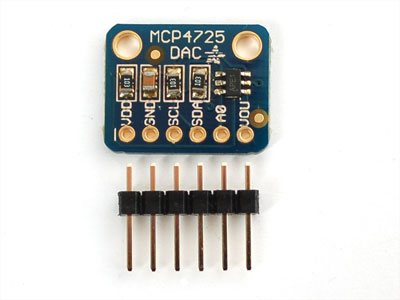
Figure 9-56. MCP4725-based DAC module
A DAC is useful when there is a need for a continuously variable signal, such as a control voltage for some other circuit or device. A DAC can also be used to generate a waveform such as a ramp or sine wave.
With the 100 Kb/s communications rate of standard mode I2C used with an AVR microcontroller it isn’t possible to achieve the update rate possible with faster I2C interface types, but a DAC can still generate a respectable low-frequency sine wave. The downside is that the AVR will usually be doing nothing else but updating the DAC to produce a waveform.
Waveform generators
While it is possible to generate low-frequency waveforms directly with an Arduino and a DAC module, for quality waveforms beyond about 1 KHz an outboard circuit is necessary. One such device is the direct digital synthesis (DDS) module shown in Figure 9-57.
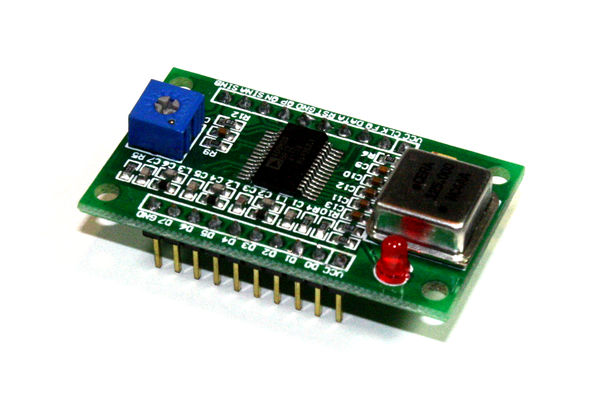
Figure 9-57. AD9850-based DDS module
The AD9850 IC can generate both square and sine waves from 1 Hz to 40 MHz. You can download the datasheet for the AD9850 from Analog Devices. The AD9850 uses its own unique interface, and can be controlled using either an 8-bit parallel or a serial interface. Arduino libraries for the AD9850 are readily available.
User Input
Sometimes its is necessary for a human to interact directly with an Arduino project, and this means pushbuttons, knobs, keypads, and joysticks. In addition to the modules described in this chapter, you can also purchase the bare components and mount them as you see fit.
Keypads
The term “keypad” usually refers to a small arrangement of switches with key caps, typically in a 3 × 3, 3 × 4, or 4 × 4 grid. It can also refer to a so-called membrane keypad, which is an array of thin membrane switches on a PCB. The keys are typically marked with letters and numbers, like the examples shown in Figure 9-58. Keypads aren’t limited to small rectangular arrays, but can be found in a wide range of styles and layouts. In fact, a computer keyboard is just a large keypad.
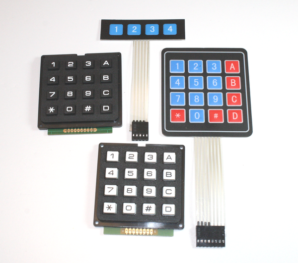
Figure 9-58. An assortment of keypads
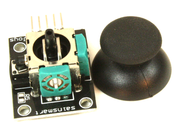
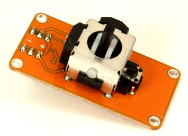
Joysticks
Joysticks typically come as one of two types: continuous analog and discrete digital. A continuous analog joystick, like the one shown in Figure 9-59, uses two potentiometers, each connected to the x- and y-axes. The values read from the potentiometers indicate how far the joystick has moved and what position it is currently in.
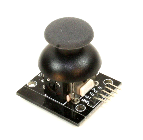
Figure 9-59. Analog joystick module
A discrete digital joystick uses small switches or some other type of detector to sense when the joystick has moved to its maximum extent in either or both of the x or y directions. These types of joysticks were used with early low-cost consumer games and personal computers. They are all-or-nothing devices, but they are cheap to manufacture and they don’t have the issues with dirt and wear that can affect an analog joystick. Many LCD shields incorporate a discrete joystick.
Potentiometers and Rotary Encoders
A potentiometer is a variable resistor, typically used for control input. A potentiometer, or pot, can be used in a light dimmer module, as a volume control, as a control input for a test instrument, or as an input for a wide variety of analog circuits. The TinkerKit T000140 and T000150 modules are examples of potentiometers.
A rotary encoder, like the one shown earlier in Figure 9-36, can also be put to use as a user input device. Instead of producing a variable voltage that must be converted into digital numbers so an AVR microcontroller can use it, the rotary encoder produces digital output that can be used directly.
User Output
The ability to display information to a user allows you to make something truly interactive. It might be simple status conveyed by LEDs, or complex messages or images on an LCD or TFT display screen. Whatever form they take, output devices give the user immediate feedback in response to command inputs.
There are a variety of displays available that can be used with an Arduino. The LCD display shields described in Chapter 8 utilize these same components, but in a more convenient form. There are, however, situations where a shield may not be appropriate, and in these cases an LCD display component that can be mounted in a specific fashion may be the better choice.
Note
More examples of displays in the form of shields for Arduino boards are described in Chapter 8. Be sure to look there as well. Unless you absolutely must have a display with bare pins, a shield is a much easier way to go.
Text Displays
Some of the more common and inexpensive text-only displays have anywhere from 1 to 4 lines, with each line capable of displaying 8, 16, 20, 24, 32, or 40 characters. Of course, as the display density increases, so does the price. A 1-line 8-character display can be had for around $2, while a 4-line 40-character display goes for somewhere in the neighborhood of $18.
ERM1601SBS-2
The ERM1601SBS-2 LCD display is a 16 × 1 display with white characters on a blue background. A typical module is shown in Figure 9-60. These displays utilize an HD44780 or KS066 controller chip and LED backlighting, and this particular unit sells for around $3. Similar products are available with black letters on a yellow-green background and black letters on a white background.
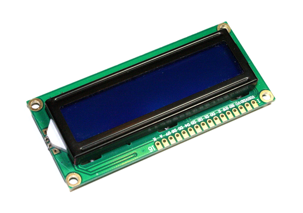
Figure 9-60. ERM1601SBS-2 display module
ST7066 (HD44780)
This is a 16 × 2 line LCD display with a simple parallel interface that uses either an HD44780 or an ST7066 controller. It is the same part as found on the LCD display shields from Adafruit, SparkFun, SainSmart, and other sources. Figure 9-61 shows an example of this type of display. These sell for about $10.
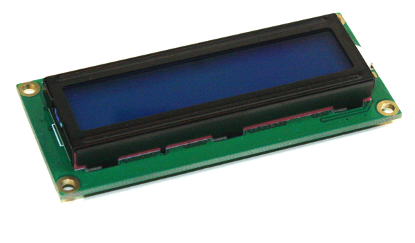
Figure 9-61. 16 × 2 display using an HD44780 or ST7066 controller
You may notice that the ERM1601SBS-2 shown in Figure 9-60 looks a lot like the display shown in Figure 9-61. This is because they both use the same ICs to drive the LCD. The only major difference is that one has a single-line display and the other has a two-line display.
Other types of both nongraphical and graphical LCD displays are available from a variety of sources. Occasionally you can find new surplus displays at very low prices, and if they use a standard controller chip they can usually be easily integrated into an Arduino project. The downside is that these surplus displays often have special-purpose symbols built in—so you might get a great deal but have a display with symbols for a microwave oven or a lawn sprinkler system that you don’t need. (Or then again, maybe you do…)
Graphical Displays
Graphical displays are available using LCD, TFT, or OLED technologies in both monochrome and color formats. The TFT and OLED devices look much better than a simple dot-addressable LCD, but the prettiness comes at a price.
ERC240128SBS-1
The ERC240128SBS-1 display shown in Figure 9-62 is a 240 × 128 dot-addressable LCD display with an 8-bit parallel interface. It is available from BuyDisplay.
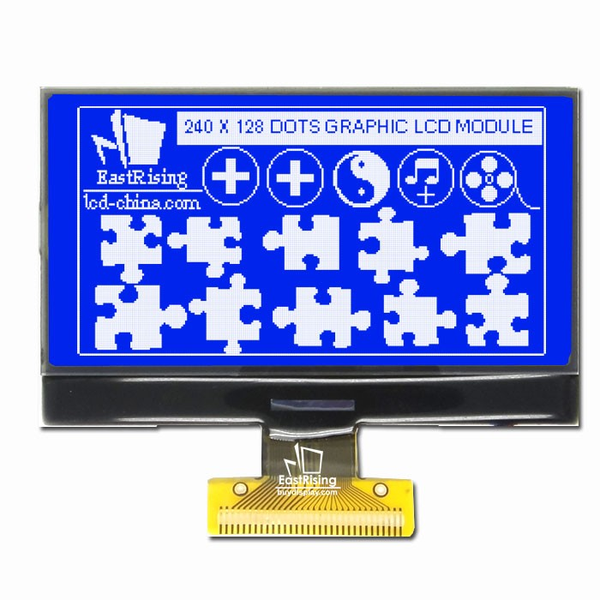
Figure 9-62. 240 × 128 color TFT display
ST7735R
An example of another type of display is the 128 × 160 TFT unit sold by Adafruit and shown in Figure 9-63. This display has a 1.8 inch (4.6 cm) diagonal size display and is capable of 18-bit color selection for 262,144 different shades. It uses an ST7735R controller with an SPI interface, and even includes a microSD card carrier on the back side of the PCB.
Support Functions
Most modules provide input or output functions. Not many have functions that could be classified as non-I/O support. Those that do generally fall into the categories of clocks and timers.
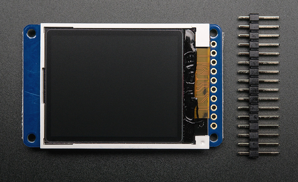
Figure 9-63. 1.8” color TFT display module
Clocks
There are multiple types of real-time clock (RTC) ICs available, including the DS1302, DS1307, DS3231, and PCF8563. They all do basically the same thing: keep track of the time and date. Some have on-board EEPROM and some do not. Some use a nonstandard interface, some use SPI, and others use I2C. Other than the obvious interface differences, the primary differences are largely a matter of accuracy as a function of stability over time, temperature sensitivity, power consumption, and cost.
Four common RTC modules encountered are those based on the DS1302, DS1307, DS3231, and PCF8563 ICs. The modules will usually have a holder for a “coin cell"–type battery, often a CR2032 or an LIR2032. Independent testing has shown that the DS3231 has the best overall long-term stability, but the other RTCs are perfectly usable. The modules with external crystals can suffer from temperature-induced drift, and all of them will deviate to some degree over extended periods of time.
DS1302 RTC module
The DS1302 RTC IC (Figure 9-64) uses a nonstandard serial interface. It’s not SPI, but it is clocked. One line carries data, one is a clock signal, and another is the chip enable (CE) line. This is what Maxim (née Dallas Semiconductor) refers to as a three-wire interface. Figure 9-64 shows a typical DS1302 module. More information about the DS1302 is available from Maxim Integrated.
DS1307 RTC module
The DS1307 RTC is an I2C device. It is not code- or pin-compatible with the DS1302, but the end result is the same. Refer to the datasheets from Maxim for details. Figure 9-65 shows a DS1307 RTC module from Tronixlabs.
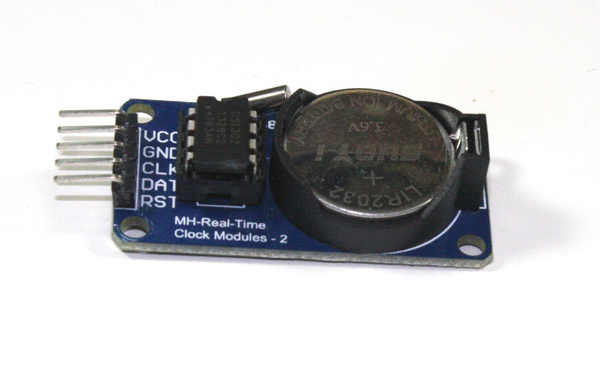
Figure 9-64. A DS1302 RTC module
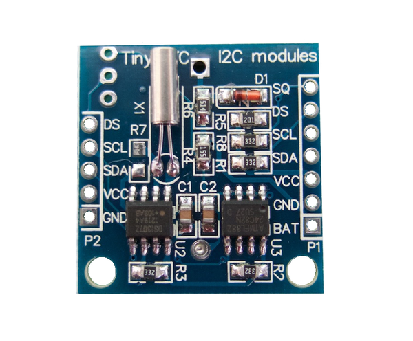
Figure 9-65. A DS1307 RTC module
DS3231 RTC module
Like the DS1307, the DS3231 RTC uses an I2C interface, and it is code-compatible with the DS1307. The main difference is the accuracy. The DS3231 uses an internal crystal. This makes it less temperature sensitive. Figure 9-66 shows a typical DS3231 RTC module.
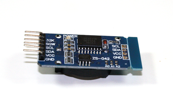
Figure 9-66. A DS3231 RTC module
RTC module using PCF8563
The PCF8563 is another RTC IC with an I2C interface. It is an NXP part, and its internal registers are completely different from the Maxim DS1307 or DS3231. Figure 9-67 shows a typical module based on the PCF8563.
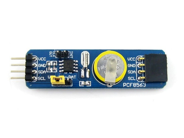
Figure 9-67. A PCF8563 RTC module
Timers
Although the AVR MCU contains a built-in watchdog timer, there are modules available that perform essentially the same function. One potential application for an external watchdog, or resettable countdown timer to be more precise, is when it makes sense for the timer reset signal to come from an external device instead of from the AVR itself. Consider a rotating mechanism fitted with a magnetic sensor that will emit a pulse for every revolution of the shaft. If the pulses are used to reset an outboard watchdog timer it can detect when the mechanism fails and stops turning. By either using an interrupt or just polling the status of the countdown timer the MCU can detect the fault condition and take appropriate action.
Many of the outboard timer modules seen in the wild use a 555 timer. A MOSFET is used to discharge the timing capacitor and reset the timer whenever a reset pulse is applied. Some other timer modules from Asian sellers use a black blob of epoxy to hide whatever is doing the actual timing on the PCB. I would avoid these, since there is no easy way of knowing what is inside without destroying the IC under the blob.
If you are interested in external countdown timer modules, I would suggest picking up a copy of Howard Berlin’s book The 555 Timer Applications Sourcebook (see Appendix D). The original 1979 edition is out of print, but you can still find copies of it on Amazon, and there is newer, but slightly different, version available. The Australian company Freetronics sells an inexpensive watchdog timer module based on a 555 timer.
Connections
Over the past several years a trend has begun to emerge in module and shield interconnect methods where modular connectors are replacing the connector pins and sockets once found on both shields and modules. Often referred to as systems, these involve a set of modules and some form of interface shield that all use the same connector types and pinouts for voltage, signal, and ground.
The TinkerKit modules (listed in Table 9-9) are just one example of a module connection system. Another is the Grove line of modules and associated base interface shields from Seeed Studio. Other shields feature three- and four-pin connectors for use with prefabricated cables with mating connectors at each end, such as the passive patch shield kit shown in Figure 8-21.
Working with Naked Jumper Wires
Let’s say that you plan on permanently connecting a single module to an Arduino (perhaps it will be embedded somewhere and left to do its job for extended periods of time), and you don’t want to take the time to build your own connector. That’s fine; there is nothing wrong with using jumpers so long as you take some simple steps to make the connections more physically reliable.
The crimp socket (or pin) terminals used in jumper wires are the same terminals used in modular connectors. The difference is that a jumper wire has just one terminal, whereas a connector will have two or more. The more crimp terminals there are in a connector, the more robust it will be. This is due to the increased mechanical friction of multiple socket terminals all working together in the same connector housing.
A single jumper wire can wiggle and flex, and it doesn’t have the mechanical grip afforded by a gang of terminals in a single connector housing. One way to achieve a more reliable connection is to apply a small blob of silicon rubber (also known by the brand name “RTV”) to hold the jumper connectors in place on a module’s pins. It might not be as elegant or robust as a modular connector, but unless the module is operating in a high-vibration environment like an RC vehicle or a machine tool in a factory, it will hold up just fine.
Just don’t go crazy with the silicon, as you might want to remove it at some point and replace the module. A sharp razor knife will cut the soft silicon rubber and not damage the jumper (if you are careful, of course).
Module Connection Systems
In general, a shield with connectors—whether the open frame style used by TinkerKit or the closed shell types used by the Grove components and others—can also be used with either individual jumpers or crimped socket headers, just like the shields and modules with bare pins. Prefabricated connectors make it easier for someone to connect a module and not worry about how the pins are wired, so long as the module is designed to connect to a particular shield with the same types of connectors. This is the approach that the TinkerKit and Grove modules have taken. (More information about the Grove modules can be obtained from the Seeed Studio website.)
Other systems, like the TinyDuino modules from TinyCircuits, utilize small surface-mounted multipin connectors. Figure 9-68 shows a few examples of these types of modules. While technically not modules in the sense of the modules described in this chapter, this approach shows just one of the many ways to deal with the interconnect problem. TinyCircuits also produces sensor modules with the same type of connector, and they have extension cables available. These things are very small (look at the USB connector on a Nano and then compare that to Figure 9-68), and the first thing that popped into my mind when I saw them was “model rocket.” More information is available at the TinyCircuits website.
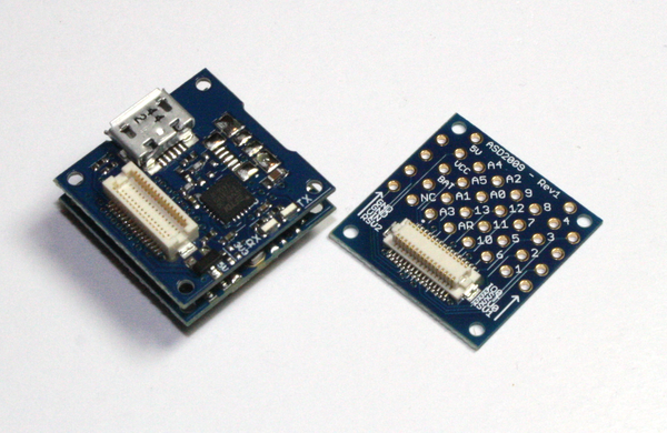
Figure 9-68. Example modules available from TinyCircuits
The connectors are the real problem with using modules and shields made for a particular interconnect system. There is no consistent standardization across all the different manufacturers, and no guarantee that a module from one vendor will just plug in to an interface shield from somewhere else. One way to address this is to create both the base interface shield and a selection of modules to go with it, which is exactly what the folks behind the TinkerKit products elected to do. When considering a particular module, pay attention to the connection method it uses. You should also be prepared to purchase additional cables, and perhaps some prototyping modules in order to interface with components not made for a paricular connector system. Or you could elect to build your own custom cables, which is covered in the next section.
Building Custom Connectors
Connectors are not only easier to use, they are also more robust and reliable than jumpers. But not having connectors isn’t all that bad. An interface shield like the sensor interface shield from SainSmart shown in Figure 8-3 has the I/O pins arranged in neat rows with 0.1 inch (2.54 mm) spacing. A connector header, like those shown in Figure 9-69, with the same spacing and holes for crimp terminals will mate with the pins and make a solid connection.
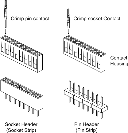
Figure 9-69. Pin and socket headers for crimped terminals
Connector shells and crimp terminals come in a variety of styles. The shells, or housings, are available with positions for one or more terminals. You may occasionally come across a jumper wire with single-position plastic housings at each end instead of the heat shrink insulation that is also used. I prefer the plastic shells, even if the jumpers do cost a bit more.
For those who just want to connect one or two modules and not worry about the jumpers coming loose and falling off, the socket header approach is an alternative worth considering. The downside is that you will need to invest in a crimping tool and a good pair of wire strippers. Figure 9-70 shows a crimping tool, and Figure 9-71 shows how it works.
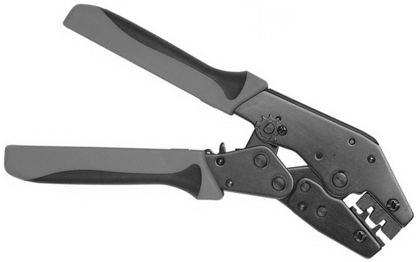
Figure 9-70. Typical terminal crimping tool
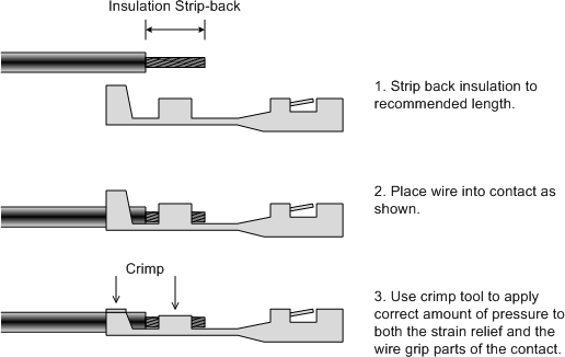
Figure 9-71. How a crimped terminal is attached to a wire
Figure 9-72 shows a three-position socket terminal header connected to a temperature and humidity sensor module (a KEYES KY-015). This arrangement allows the sensor to be mounted where it is needed and connected to an interface shield. A small amount of clear silicon between the connecter housing and the module’s PCB can be used to ensure that it won’t easily come loose from the module.
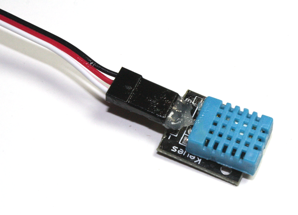
Figure 9-72. Using a three-position header to connect a sensor module
Choosing a Connection Method
The trade-off boils down to either using modular connectors and prefabricated cables that are reliable and robust but require a matching set of components or making your own connections, either using jumper wires with crimped socket terminals or making your own socket header for a particular module. Which path you choose may depend on how much effort you want to expend to connect modules to an Arduino or a shield, and how “locked in” you want to be to a particular connection scheme.
You may have noticed that I didn’t discuss one other available method for connecting modules: soldering. This is always an option, but unless a module is intended to become a permanent part of something it should be considered a last resort. Soldering a module directly to wires or onto a PCB makes a solid connection, but it’s not easily undone and it can be ugly. It also means that you will have one less module to use in other projects.
That being said, you may have noticed in Figure 9-12 that the relay and temperature sensor modules are soldered directly onto a prototyping shield for the Arduino thermostat. The reasoning here is that the module will not be taken out of service any time soon, and it will operate in a somewhat nasty environment inside of an electric heater, with thermal fluctuations and fan vibrations. So, I elected to make it relatively permanent. While I may regret that at some point, for now it works just fine. You will need to make the soldering decision for yourself should the occasion arise.
Sources
The sources listed in Table 9-11 are just a sample of the companies selling Arduino-compatible components and modules. They are just the ones I happen to be aware of, and I’ve done business with most of them. There are many other sellers that I don’t know about, but you may discover them if you look around on the Internet. And don’t forget eBay.
| Distributor/vendor | URL | Distributor/vendor | URL |
|---|---|---|---|
Adafruit |
Mouser Electronics |
||
Amazon |
RobotShop |
||
CuteDigi |
SainSmart |
||
DealeXtreme (DX) |
DFRobot |
||
Seeed Studio |
Elecfreaks |
||
SparkFun |
Elechouse |
||
Tindie |
Freetronics |
||
Tinkersphere |
iMall |
||
Tronixlabs |
ITEAD Studio |
||
Trossen Robotics |
KEYES |
Summary
This chapter has provided a survey of some of the various modules and components available for implementing input and output functions with an Arduino (or just about any modern microcontroller, for that matter). As was stated earlier, you can find many of the capabilities described here on a shield, but there may be times when a shield isn’t appropriate. With an Arduino Nano and some sensors, input components, and some type of output, you can arrange things to suit your particular requirements.
With a web browser and access to the Internet you can easily locate hundreds of different I/O components that can be connected to an Arduino, or even just a bare AVR IC. Sources range from large electronics distributors like Digi-Key, Mouser, and Newark/Element14 to companies like Adafruit, SparkFun, SainSmart, and CuteDigi. There are also distributors that specialize in low-cost new and surplus components.
When it comes to purchasing sensors for an Arduino project, there are a few points to keep in mind:
-
Does the device use a simple interface (discrete digital, SPI, I2C, etc.)?
-
Does the device come with technical data (or is it readily available)?
-
Are Arduino software libraries available?
Depending on your programming skill level, item 3 may or may not be a dealbreaker for you. Personally, I put much more emphasis on items 1 and 2, mainly because I have better things to do than reverse engineer a complex interface for some really cool-looking thing I picked up for sale through eBay. For me, it makes more sense to buy the not-so-cool thing and get the technical information I need to get it up and running. The main thing is getting something that will do the job, and at a price that is within your budget.