
Chapter 13. Model Rocket Launcher: A Design Study
This chapter is a departure from the previous three chapters. Instead of using an example project (or projects, in the case of Chapter 10) to illustrate how the concepts, tools, and components described in earlier chapters are used in real applications, this chapter illustrates how to perform a design study. We won’t actually build anything, but we will define some possible approaches, identify suitable tools and components, and evaluate design trade-offs. This type of engineering activity applies to more than just model rocket launchers; it can be applied to an Arduino design project with any degree of complexity.
Note
Remember that since the main emphasis of this book is on the Arduino hardware and related modules, sensors, and components, the software shown is intended only to highlight key points, not to present complete ready-to-run examples. The full software listings for the examples and projects can be found on GitHub.
Overview
An Arduino-controlled rocket launcher is an interesting application for several reasons: first, it is very extensible and you can take it as far as you want (and can afford) within the limits imposed by the Arduino hardware; second, physically the launcher can be anything from a small plastic box with a switch and an LED to a console with digital readouts and a keyswitch or two; third, the launcher can support a wide range of functions beyond simply applying current to an igniter. It could have WiFi or Bluetooth connectivity, the ability to continuously check igniter continuity, synthetic speech generation for the countdown and launch status reports, range safety inputs, and even the ability to disconnect DC power from a rocket prior to launch to keep the internal batteries fully charged. How much (or how little) effort you want to put into it will depend on your objectives, abilities, and finances.
By the end of this chapter you should be able to make informed decisions about what hardware to buy, how difficult the software will be to write and test, and how to anticipate the level of effort a given design will entail. Using the material presented in earlier chapters you should be able to create a parts list and get an idea for how much the design will cost and how difficult it will be to build. You should also be able to create a preliminary block diagram and software flowchart for your design. Once all these things are in place, all that remains is gathering up the parts, assembling it, and then creating and loading the software to make it go.
Tip
Before attempting to build something like this, make sure you understand the safety considerations that are involved with something like a rocket launcher. The National Association of Rocketry (NAR) and the Tripoli Rocketry Association have published guidelines for safely handling and launching model rockets, and many states have basic rules in place regarding where and when you can launch, and what qualifies as a model rocket.
The Design Cycle
When we design anything with even a moderate degree of complexity, it is rare that we don’t find ourselves going back to an earlier step in the process to make modifications or seek alternatives. Sometimes that might even mean tossing out the original design and starting over. This is not uncommon. Design is an iterative process, and as it progresses things become apparent that weren’t obvious at the outset. It is almost impossible to anticipate everything in advance.
The design process follows the general outline presented in Chapter 10. We begin with a set of objectives. The objectives are refined to create functional requirements. From the functional requirements we can identify the types of hardware and software that will fulfill the requirements. Then we look at the details of the selected components and techniques to evaluate their suitability. Figure 13-1 shows how the design cycle works.
At the end of each step we will stop and consider what we’ve done up to that point. If there is problem, that is where we want to evaluate how to resolve it. Depending on the type and severity of the problem, we could elect to step back and revise a previous step, or we might decide to drop something that isn’t essential and go forward with reduced expectations. We might also find issues during the activity for a particular step. Say, for example, that we discover that a particular shield, sensor, or module simply isn’t available, and we can’t justify building it ourselves. In that case we need to stop, step back, and see what drove that selection in the first place and if it can be revised to accommodate the current situation.
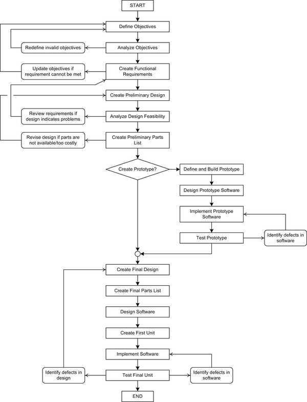
Figure 13-1. The design cycle
In some cases it may not be necessary to build a real prototype. This is often the case when a design consists primarily of ready-made modules, as is the case with many Arduino-based designs. I like to build prototypes with prototyping platforms I have created or purchased, such as the Duinokit and solderless breadboard used in Chapter 10, or the Arduino-on-a-board used in Chapters 11 and 12. It allows me to connect things without resorting to soldering wires and drilling holes, and still get the same functionality that the finished unit will have. You may find that you can skip the prototyping step for some design projects, but be aware that if a problem does pop up in the final design it may be expensive and time-consuming to deal with it.
Note
In a real-world situation the cost of dealing with a defect in the design or implementation, either hardware or software, increases as the project progresses through the steps shown in Figure 13-1. In other words, it is much cheaper to fix an invalid functional requirement than it is to rewrite defective software or deal with a hardware design flaw. By the same token, it is easier and cheaper to deal with a problem in a prototype than it is to address a problem in a design that is about to go into production. This is why building prototypes is so popular.
Objectives
The first step for a design activity is to decide what objectives the design is intended to meet. We may not have all the details starting out, but we should be able to decide on the fundamental characteristics, even if it’s just a small set initially. The list of objectives can grow over time, sometimes dramatically. In fact, it is often a challenge to keep the design objectives in line with reality, particularly when the person defining the objectives is not the same person who will be building the final design. Fortunately, this is not the case here. So long as we keep our enthusiasm and optimism in line with reality we should be fine.
When setting down a list of objectives I recommend organizing the list by importance. In other words, put the “must have” features at the top of the list, and the “bells and whistles” features toward the end of the list. That will allow you to trim off items from the list should the level of effort, cost, or time constraints exceed acceptable limits without losing the essential functionality of what you’re trying to build.
Here is my list of prioritized objectives for an automatic rocket launch controller (aka launcher). The primary objectives are:
-
The launch controller will incorporate a countdown timer with presettable times (5, 10, 15, 30, and 60 seconds).
-
The countdown may be aborted at any time for a number of reasons (given next).
-
The launch controller must have a key-operated safety interlock (arming) switch. The launcher will not start the count or activate the igniters unless the interlock is set to the “on” position.
-
The launch countdown timer is started by pressing a pushbutton switch.
-
The launch countdown cannot proceed unless a safety switch is depressed prior to pressing the countdown start button and during the entire period of the count. This could be a handheld pendant or small box, and it is separate from the count start switch.
-
If the safety switch is released prior to launch, the countdown will abort and the controller will enter a “safe” mode (igniter circuits disabled and grounded).
-
The launcher must be capable of energizing multiple igniters at the same time. Two would be a minimum number, with up to eight if possible.
-
Each igniter should be monitored independently of any others to detect circuit continuity problems prior to launch.
-
A continuity failure of any igniter will abort the launch (the same response as a premature release of the safety switch).
-
The controller will use a flashing LED to track the countdown in seconds. Other LED indicators will show the status of the controller (armed, counting, safety abort, or igniter fault).
The secondary objectives are as follows:
-
A 7-segment LED display will display the countdown.
-
A 7-segment LED display will display the current time.
-
A 16 2 LCD will display system status data and error messages.
-
All components will be mounted in a low-profile sloped-top console chassis.
And these are the optional objectives:
-
The launch controller will have the ability to activate external devices at specific points in the countdown sequence, such as ground power disconnect, launch warning siren, and on-board electronics activation (camera start and so on).
-
The controller will have a connector for attaching a large 7-segment display for group event display purposes.
-
The controller will incorporate the ability to generate synthetic speech for countdown and status announcements.
-
A Bluetooth interface will be used to connect to a remote weather monitoring system (primarily used to detect excessive wind speed in the launch area). If this is used then the system must also have the ability to abort on out-of-range wind speed and indicate this to the launch director (the user).
That’s a rather extensive and ambitious list, to be sure. Achieving the primary objectives doesn’t seem like it would be too difficult, which is what we want for primary objectives. The secondary objectives are a bit more challenging, and the optional objectives, while intriguing, could tax the stamina of the builder (not to mention costing more money).
Selecting and Defining Functional Requirements
The way I’ve written the objectives allows us to move directly into the functional requirements with very little translation. A requirement needs to be clear, concise, coherent, and verifiable, and in some cases the objectives are worded like requirements, so that makes it easier for us.
The big question now is, how many of the objectives do we adopt and move forward with as functional requirements? In order to answer that question we need to use some type of scoring system to determine how hard, how expensive, and how necessary each objective will be to achieve.
We’ll start with the primary objectives. Table 13-1 shows a list of the primary objectives with my best estimates for difficulty, expense, and overall necessity. Each aspect is scored on a scale of 1 to 5, with 1 being the least and 5 being the most.
| Objective | Difficulty | Expense | Necessity |
|---|---|---|---|
1.1 |
2 |
2 |
2 |
1.2 |
3 |
2 |
5 |
1.3 |
3 |
2 |
5 |
1.4 |
2 |
2 |
4 |
1.5 |
2 |
3 |
5 |
1.6 |
2 |
1 |
5 |
1.7 |
3 |
3 |
3 |
1.8 |
4 |
3 |
5 |
1.9 |
3 |
2 |
5 |
1.10 |
3 |
2 |
2 |
From this we can conclude that objective 1.1, a presettable countdown timer, could be replaced with a fixed 10- or 15-second count if need be. It is also apparent that objective 1.10, the blinking lights, might fall under the category of “bells and whistles,” or secondary objectives, and could be dispensed with if necessary (although we would likely want to keep at least the countdown LED to let us know something is happening).
We can do the same thing for the secondary and optional objectives, as shown in Table 13-2.
| Objective | Difficulty | Expense | Necessity |
|---|---|---|---|
2.1 |
3 |
3 |
2 |
2.2 |
3 |
3 |
2 |
2.3 |
3 |
3 |
2 |
2.4 |
3 |
3 |
2 |
3.1 |
4 |
4 |
1 |
3.2 |
4 |
3 |
1 |
3.3 |
4 |
4 |
1 |
3.4 |
4 |
4 |
1 |
You may notice that there is an interesting pattern emerging between Table 13-1 and Table 13-2. The primary objectives are all relatively inexpensive and easy to implement. Also, with the exceptions of 1.1 and 1.10, they are all necessary. In Table 13-2 we see that as the expense and difficulty increase, the necessity decreases. None of the optional objectives are necessary, although they would be really fun to implement.
I didn’t intentionally arrange the objectives like this when I wrote them down; they just fell out that way. Honest. I suppose it might be the result of doing this sort of thing quite a bit over the years, but in any case you’ll want to organize your objectives first on the basis of necessity, then on the basis of either cost or difficulty, depending on what is more important to you: money or time.
This brings us to a trade-off point. If something is necessary but it will be expensive, do we eliminate something that is not as necessary to keep the project budget sensible, or would we be willing to throw more money at it to get both objectives met? In some cases, such as choosing between the primary and optional objectives, the choice is clear-cut. The end result might not be as dazzling as it could otherwise be, but we won’t break the bank building it, either. It will still launch rockets just fine. On the other hand, when choosing between two primary objectives with equal necessity and equal expense, such as objectives 1.1 and 1.10, the choice could hinge on how difficult the objectives will be. In this case it would probably be easier to install one rotary switch to select the countdown time than it would be to drill holes for LEDs, wire and install them, and then create the software to control them all.
For the sake of continuing with the design analysis, let’s assume that we will keep all of the objectives so we can see how they will drive the design and component selections in later steps. Table 13-3 lists the functional requirements derived from the objectives.
| Req # | Description |
|---|---|
1.1 |
The launch controller will incorporate a countdown timer. At the count of zero, the igniter(s) will be energized. |
1.1.1 |
The countdown timer will have five presettable times of 5, 10, 15, 30, and 60 seconds. |
1.1.2 |
The countdown times will be selected using a five-position rotary switch. |
1.1.3 |
If the countdown time is changed in mid-count the countdown will be aborted. |
1.2 |
The countdown may be aborted at any time for a number of reasons (given below). |
1.2.1 |
The countdown will be aborted if any igniter circuit is open that should be closed (see 1.7.1 and 1.9.1). |
1.2.2 |
The countdown will be aborted if the count time is changed while the countdown is active. |
1.2.3 |
The countdown will be aborted if the safety switch is released during the count. |
1.3 |
The launch controller must have a key-operated safety interlock (arming) switch. |
1.3.1 |
The launcher will not start the count or activate the igniters unless the interlock switch is set to the on position. |
1.3.2 |
The countdown will abort if the interlock switch is set to off during the countdown. |
1.4 |
The launch countdown timer is started by pressing a pushbutton switch. |
1.4.1 |
A “launch” button will be used to start the countdown. |
1.4.2 |
The launch button will not function unless the range safety switch is engaged. |
1.5 |
The launcher will use a range safety switch to control the countdown and launch. |
1.5.1 |
The launch countdown cannot proceed unless a safety switch is depressed prior to pressing the launch button. |
1.5.2 |
The range safety switch must be manually engaged during the entire period of the countdown. |
1.5.3 |
The range safety switch can be a handheld pendant or small box, and it must have at least 10 feet (3 m) of electrical cable. |
1.6 |
If the countdown is aborted for any reason the launcher will enter “safe mode.” |
1.6.1 |
In safe mode all igniter lines will be de-energized and grounded. |
1.6.2 |
Exit from safe mode will require that the launcher be disarmed using the safety interlock switch. |
1.7 |
The launcher must be capable of energizing multiple igniters at the same time. |
1.7.1 |
The launcher will support up to six active igniter circuits. |
1.7.2 |
A rotary switch will be used to select the number of active igniter circuits. |
1.8 |
Each igniter should be monitored independently of any others to detect circuit continuity problems prior to launch. |
1.8.1 |
Each igniter circuit must have continuity to verify that the igniter is connected. |
1.8.2 |
The sense current used to determine continuity shall not exceed 250 uA on any igniter circuit. |
1.9 |
A continuity failure of any igniter will abort the countdown timer. |
1.9.1 |
The countdown will not start if any active igniter circuit has no continuity. |
1.9.2 |
The countdown will abort if any active igniter circuit loses continuity during the count. |
1.9.3 |
The launcher will use LEDs to indicate active and ready igniter circuits (see 1.1.2). |
1.10 |
The controller will use LEDs to indicate the countdown and status. |
1.10.1 |
A flashing LED will track the countdown in seconds, one flash per second. |
1.10.2 |
An array of LEDs will show the active state and continuity of the igniter circuits. |
1.10.3 |
An LED will indicate the active state of the range safety switch. |
1.10.4 |
An LED will indicate a range safety abort. |
1.10.5 |
An LED will indicate the interlock switch state. |
1.10.6 |
A flashing LED will indicate when the launcher is in safe mode after an abort. |
2.1 |
A 7-segment LED display will display the countdown. |
2.1.1 |
A 2-digit 7-segment red LED display will be used to display the countdown. |
2.1.2 |
The countdown will display dash characters after a successful launch. |
2.1.3 |
In event of an abort the display will show the word “Abort.” |
2.2 |
A 7-segment LED display will display the current time. |
2.2.1 |
A 4-digit 7-segment yellow LED display with HH:MM format will show the current time. |
2.2.2 |
The time display will be settable using pushbuttons on the front panel of the launcher. |
2.2.3 |
The time display will be in 24-hour format. |
2.3 |
A 16 × 2 LCD will display system status data and error messages. |
2.3.1 |
A 16 × 2 LCD display will show messages for readiness status and faults. |
2.3.2 |
The LCD display will also be capable of displaying messages from external sources such as a remote weather station. |
2.4 |
All components will be mounted in a low-profile sloped-top console chassis. |
2.4.1 |
A low-profile metal chassis will be used to contain the launcher. |
2.4.2 |
The chassis will be at least 14 inches wide by 10 inches (35.5 × 25.5 cm) deep, with a height of 1.5 inches at the front and 3 inches at the rear of the chassis (3.8 × 7.6 cm). |
3.1 |
The launch controller will have the ability to activate external devices at specific points in the countdown. |
3.1.1 |
The controller will be capable of activating external devices via relays at user-definable points in the countdown. |
3.1.2 |
The action points will be set using a USB connection to the Arduino in the launcher. |
3.2 |
The controller will have a connector for attaching a large 7-segment display for group event display purposes. |
3.2.1 |
The signals to the internal two-digit countdown display will be duplicated to a connector on the rear of the chassis. |
3.2.2 |
The external display signals will be controlled by a high-current IC to provide sufficient drive current. |
3.3 |
The controller will incorporate the ability to generate synthetic speech for countdown and status announcements. |
3.3.1 |
The launcher will incorporate a speech synthesis shield to produce intelligible speech. |
3.3.2 |
The speech output will be user defined. |
3.4 |
A Bluetooth interface will be used to connect to a remote weather monitoring system. |
3.4.1 |
The user can define an upper limit for wind speed. Exceeding the limit will cause a launch abort. |
3.4.2 |
An LED on the front panel will indicate a wind speed launch abort. |
I endeavored to maintain a one-to-one relationship to the objectives listed earlier, but there is some deviation, mainly involving the elimination of redundancy.
Tip
This design utilizes a “range safety switch” that must be held down (active) during the countdown. This is an essential safety feature. In practice there could be two people involved: a launch director and a range safety officer. It is the range safety officer’s job to abort the launch if anything is not as it should be prior to ignition (e.g., wind, or people in the launch area).
Creating the Preliminary Design
Now that the functional requirements have been defined, we can see some obvious design criteria as we read through them. We know that we are going to need two rotary switches, an LCD display, two 7-segment displays, a real-time clock of some sort, a pendant or small box with a pushbutton switch (the range safety switch), some connectors on the rear panel, some relays, and multiple LEDs of various colors.
In order to get a better idea of what will be involved in the design we can create a preliminary block diagram like the one shown in Figure 13-2. From the block diagram it becomes immediately apparent that something like an Arduino Uno isn’t going to be able to handle all the required I/O. We need to consider a Mega2560 instead. We might also want to consider more than one Arduino to spread the workload around.
Figure 13-3 is a more refined version of the block diagram. Notice that it uses one Uno for the speech synthesis, another for the Bluetooth, and a Mega2560 for the primary control functions. The ATmega2560 MCU used in the Mega2560 has multiple USART interfaces, so each of the outboard Unos can have its own dedicated communications channel.

Figure 13-2. Preliminary launcher block diagram
In Figure 13-3 several of the interfaces to external modules have been refined and designated as I2C types. In addition, the digital I/O (DIO) ports have been identified. An I/O expander (similar to what was used in the Switchinator in Chapter 10) has been selected to handle the relays and the 12 igniter status LEDs.
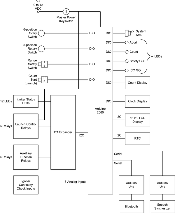
Figure 13-3. Refined launcher block diagram
Design Feasibility
So just how realistic is the design we’ve come up with? It is sufficient? Yes, undoubtedly. Is it overkill? Perhaps. Now is the time to step back and review the preliminary design with a critical eye and a willingness to cut out unnecessary or frivolous features without remorse or regret.
Feasibility is a relative assesement. In other words, feasible in relation to what? Some things that might not be feasible for someone working on the kitchen table could be perfectly feasible for another person with access to a complete shop. Budget limitations are another important concern, as are level of effort limitations. One person with a small budget and limited time cannot hope to achieve what someone else with a generous amount of money to spend and lots of time can do. Since I’m just one person, and I don’t have lots of spare time and have only a limited amount of funds at my disposal, I have to be prudent about how much I can take on and how quickly I can expect to accomplish it. I’m sure I’m not alone in that regard.
I like to use the following five criteria when evaluating the feasibility of a design and its features:
-
Does the feature or design make sense functionally?
-
Does it make sense cost-wise?
-
Is there any component that might be hard to get?
-
Are there any unsafe aspects to the feature or the design?
-
Can it be assembled, programmed, and tested by one person in a reasonable period of time?
If the answer to any of these questions is no, or even a maybe, then the component or design feature in question should be considered for removal.
The design of the rocket launcher, as represented by Figure 13-3, would indeed be a wondrous thing, but I don’t think it’s something I could expect to finish in a reasonable period of time. The better approach might be to keep it simple (as simple as possible, anyway) and create a design that can be expanded in the future.
Because of the way the objectives for the launcher were organized, trimming back the design is actually rather easy. The level 3 functional requirements define things that will be both time- and money-intensive. They also don’t contribute anything critical to the core function of the launcher, which is of course launching model rockets. I am going to designate all the level 3 functional requirements as optional future add-on features for future implementation.
Let’s call the basic launcher, which is comprised of the level 1 and level 2 functional requirements, the Phase I version. We can refer to the extended design as the Phase II version. While we’re thinking about the Phase I design we can also be looking at ways to further simplify the design without sacrificing any of the required functionality.
For example, in Figure 13-3 there is an I/O expander. What is this? It could be something like a Centipede I/O expander shield, described in Chapter 8. The Centipede has 64 digital I/O lines, so one of these could easily handle the igniter status LEDs, the 4 system status LEDs, and the 2 rotary switches. We can further simplify the wiring by using SPI and I2C as much as possible. The RTC, 16 × 2 LCD, and I/O expander are all available with I2C interfaces, and 7-segment display modules for the count and time display are available with SPI interfaces. The revised block diagram for Phase I is shown Figure 13-4.
I elected to leave the launch control relays connected to discrete digital I/O pins on the Mega2560 rather than route them through the I/O expander. This is so that there is nothing between the launch relays and the Arduino controlling them. It probably won’t make that much difference, but it does take a potential fault source out of the primary control path in the launcher. The same reasoning is why the count start, system arm, and range safety switches are connected directly to the Arduino. Also, by connecting the switches directly we can take advantage of the AVR MCU’s pin change interrupt capability, should we want to do so.
The diagram in Figure 13-4 is what we will use going forward. At some point in the future it might be feasible to try for Phase II, but not at this time. It will still be there waiting, when it is time to make it happen.
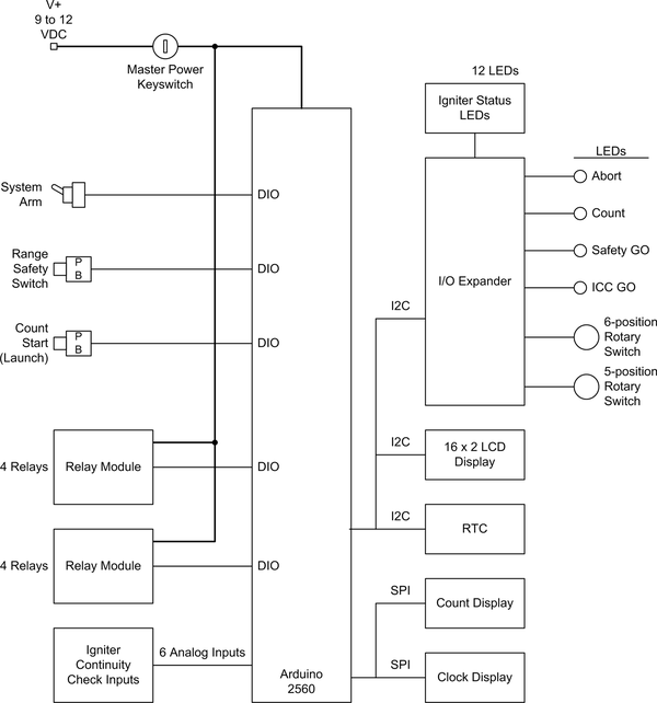
Figure 13-4. Phase I launch block diagram
Preliminary Parts List
With a preliminary design in hand for the Phase I version we have enough information to assemble a preliminary parts list. By going through the functional requirements and counting the number of times various types of controls and functions are mentioned, we can get a start on the quantities that will be needed.
The preliminary parts list doesn’t include things like prototype PCBs for patching the wiring and mounting small terminal blocks (like the ones shown in Chapter 11). These requirements can be discovered and documented when it comes time to connect it all into a working unit, either as a prototype or the final version.
| Quantity | Description | Quantity | Description |
|---|---|---|---|
1 |
Arduino Mega2560 |
1 |
2-digit 7-segment LED display |
1 |
Mega screw terminal shield |
1 |
4-digit 7-segment LED time display |
1 |
LCD display shield |
1 |
Keyed switch |
1 |
Real-time clock module |
1 |
Large pushbutton switch |
2 |
Quad relay modules |
1 |
Sloped-top metal console |
Prototype
As discussed earlier, a prototype serves several valuable functions. First off, it allows you to work with the design and its member components in a flexible and easily modifiable form. If a module or sensor doesn’t work out the way you thought it would, then it’s a lot easier to change it in the prototype than it would be by drilling more holes in a metal chassis. Second, for designs that involve a custom PCB (or two or three), there will be a lead time between when the PCB design is sent off and when the finished boards arrive and assembly can start. If you’re making a prototype, this time can be put to good use working on the software or the documentation, or both. Finally, in some cases you may have most of what you need for a prototype already on hand, and getting it to the point where it can serve as a stand-in for the final product is relatively simple. Figure 13-5 shows a simple prototype fixture for an Arduino Mega2560 built from some angle-cut sections of pine board.
Prototypes can definitely save time and hassle, but as was also mentioned earlier, sometimes you can skip over this step. In the case of the model rocket launch controller, we have a design that is not overly complex physically, there are no custom PCBs involved, and all the components are well-understood COTS parts.
You could definitely build a prototype if you wanted to do so. If you plan to incorporate the optional objectives, then a prototype would probably be a good idea. You could mount all the parts on a large board and make sure that everything works as expected before committing it to a metal enclosure. A cutting board from the kitchen would probably be about the right size. This, by the way, is where the term “breadboard” arose, in case you’ve ever wondered about that. Mounting Arduino boards, terminal blocks, and other assorted things to a board is part of a long tradition going back to the early days of radio at the start of the 20th century. Radio experimenters would literally use a breadboard, like those found in kitchens, as a base for terminal posts, tube sockets, and other components. Sometimes a schematic would be pasted to the board to give the builder something to follow. Many of the early radios were built mostly of wood, and the base for the components in the production radio wasn’t much different from the breadboard that had been used to prototype and test the radio initially.
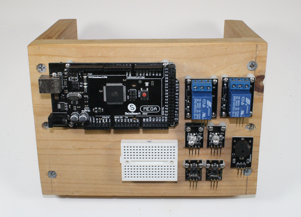
Figure 13-5. Mega2560 prototype fixture
But while the breadboard may have a storied legacy, for this design study I will assume that we will go directly to the final unit (for examples of prototypes, see the previous three chapters). For the launcher we have a good set of Phase I functional requirements and we know what primary components will be needed, so let’s move on to the final hardware and software design.
Final Design
The final design is where the functional requirements are applied, along with what was learned from the prototype (if one was created), to come up with a design that describes what the finished device will look like and how it will function. Ideally it should behave the same as the prototype, and the software should be the same, or very nearly so.
Electrical
The schematic shown in Figure 13-6 covers all of the circuitry for the launcher except the igniter continuity check circuit, which is shown in Figure 13-7. Notice that the RTC, the LCD display, and the I/O expander shield all use the I2C interface. The two 7-segment displays use the SPI interface. Only the relays use discrete digital outputs.
A typical igniter for model rockets requires around 0.5A or greater for ignition. A circuit like the one shown in Figure 13-7 can be used to determine if the igniter circuit is open or closed by measuring the voltage at the point labeled “sense.” The main concern is sensing the open or closed state of the igniter without applying enough current to cause it to ignite. With this circuit only about 2 mA is flowing through the igniter, and the 4.9V Zener diode will prevent the full launch voltage from getting back into the Arduino’s analog inputs.
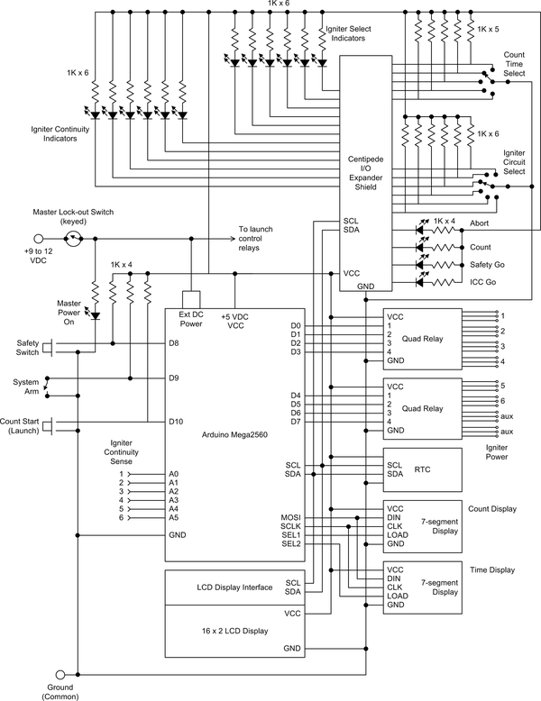
Figure 13-6. Phase I final schematic
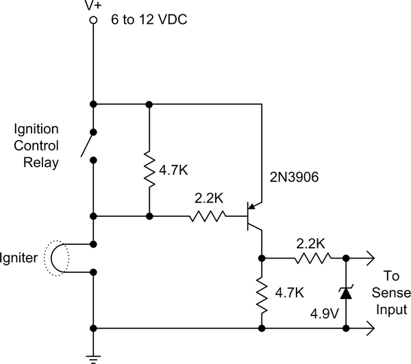
Figure 13-7. Igniter continuity check circuits
Note
Other igniter continuity check circuits have been devised, some more complex than others (there seems to be a minor cottage industry involved in creating launch controllers and continuity test circuits for model rockets). If you want to learn more, one source is J. R. Brohm’s detailed study of igniter continuity test techniques.
In the schematic shown in Figure 13-6, six continuity circuits would be connected to the six analog inputs of the Mega2560 labeled “Igniter Continuity Sense.” For this I would suggest that the six identical circuits be built using a piece of prototype board and some 0.1 inch (2.54 mm) terminal blocks, similar to what was done for input protection in Chapter 11.
Binding posts, like the types used for connecting speakers to high-end stereo receivers, can be used to connect the igniters to the launch controller. I would also suggest using binding posts to connect an external battery. If you want to have batteries in the launch controller enclosure, then an additional pair of binding posts can be used to connect the internal batteries to the igniter circuits. The will allow you to choose which power source will be used, depending on the number of igniter circuits that will be active. Connecting the igniter continuity sense circuits to the igniter binding posts is shown in Figure 13-8.
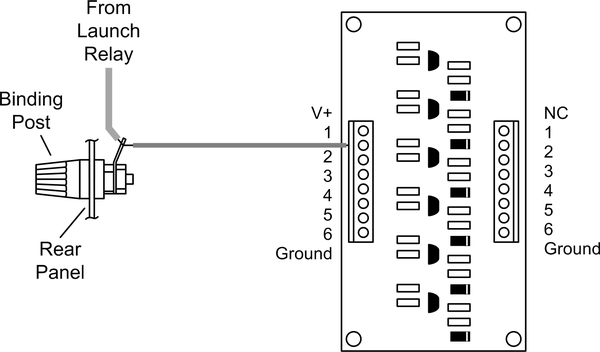
Figure 13-8. Connecting the igniter sense circuit board
The idea behind the 12 LEDs connected to the I/O expander and labeled “Igniter Continuity Indicators” and “Igniter Select Indicators” in Figure 13-6 is to show how many igniter circuits are active and what state they are in at any given time. This is determined by the six-position rotary switch S6, with the settings of 1, 2, 3, 4, 5, and 6. The corresponding continuity LEDs will glow to indicate that the selected igniters are connected and ready. After launch the continuity LEDs should be dark, and only the active selection LEDs will remain lit.
Figure 13-9 shows a different view of the wiring with an emphasis on the igniter outputs, the perfboard modules for LED and switch pull-up circuits, and the DC power routing for the various modules. Note that the individual signal lines for the I2C, SPI, and DIO and AIN functions are not shown. Instead, bus notation consisting of a slash with a number is used to indicate how many discrete signals are involved. Also not shown in the schematics are things like terminal blocks for DC power and ground.
A point of interest in Figure 13-9 is the use of one of the relays on the second relay module as an ignition safety interlock. Unless this relay is energized the igniters cannot be powered. Also note that there are four perfboard modules used to hold the igniter continuity sense circuits and pull-up resistors for various LEDs and switches. The use of 0.1 inch (2.54 mm) pitch terminal blocks makes wiring these into the system much easier than soldering, and they can be removed and replaced if necessary in the future.

Figure 13-9. Chassis wiring diagram
With schematics in hand we can now create a detailed parts list like the one in Table 13-5.
| Quantity | Description | Quantity | Description |
|---|---|---|---|
1 |
Arduino Mega2560 |
1 |
Large pushbutton switch |
1 |
Mega screw terminal shield |
8 |
Binding posts, red |
1 |
LCD display shield |
8 |
Binding posts, black |
1 |
Real-time clock module |
1 |
3.5 mm jack (single-circuit) |
2 |
Quad relay modules |
1 |
Battery holder, six D cells |
1 |
2-digit 7-segment LED display |
1 |
|
1 |
4-digit 7-segment LED time display |
1 |
Keyed switch |
Physical
I would recommend that the launcher be built into a sloped metal chassis. Although it appears that this particular enclosure is no longer available, something like the one shown in the drawing in Figure 13-10 would do nicely. This is a drawing of an old chassis that has been lying around my workshop not doing much, and I stripped out the electronics that used to be inside long ago. The chassis is a two-piece design that is 14 inches (35.6 cm) wide, 10 inches (25.4 cm) deep, and 1.5 inches (3.8 cm) at the front and 2.75 inches (7 cm) at the rear. It also has a 3.5 inch (8.9 cm) flat “shelf” along the top at the rear of the cover. It is currently too ugly to photograph, so a drawing will have to suffice.
This isn’t the final word on a chassis, by any means; it’s just something that I happened to have on hand. You may have something equally suitable, or access to a surplus electronics outlet. If it comes down to it, a nice chassis similar to this can be purchased from multiple distributors. You can expect to pay between $30 and $50 for a new sloped-front chassis.
After deciding on the enclosure, the next step is to lay out the front panel and decide where the boards and connectors will be located. With a chassis like the one shown in Figure 13-10, I recommend mounting as much as possible to the inside of the top panel. The main reason is to avoid running wires between boards and controls on the top panel. Since the rear of the chassis is just a continuation of the top panel, you won’t have to worry about disconnecting things if you need to remove the top panel piece to get at something inside.
Figure 13-11 shows a layout for the panel. This is just one way of doing it, and you might want a different arrangement. The I/O expansion shield has lots of I/O points (64 total), so there is plenty of room to grow.
Figure 13-10. Candidate chassis for the launcher
Figure 13-11. Launcher control panel layout example
Again, I recommend mounting all of the components to the inside of the cover piece, except perhaps any batteries. This makes it easy to assemble and test the launcher without also dragging along the base piece and a requisite bundle of wires to connect top and bottom components. The downside is that you will end up with screw heads on the front panel, but you can always paint over them or use flat-head screws (if the panel metal is thick enough).
If I were to actually build this (and I might, since I’ve already put this much work into it), I would mount the Mega2560 and the I/O shield under the flat section of the top of the chassis. This is a 3.5-inch-wide (8.9 cm) space that is more than wide enough to accommodate an Arduino (or two) without interfering with the controls and displays on the front panel.
One way to get everything arranged where you want it is to create a mockup using footprint models for the various boards and modules made from cardboard or foam-core material and some adhesive labels. Cut out shapes with the same dimensions as the actual parts, and some round adhesive stickers will work as stand-ins for switches and LEDs. Then arrange the mockup models on a piece of paper with a rectangular outline of the panel to get an optimal arrangement. I would do this as if I had X-ray vision and I was looking through the panel. That way I don’t have to flip things over mentally to visualize where the LED and LCD displays will go, or where the LEDs and switches will be located. You can take measurements directly from your mockup and create a fabrication drawing like the one shown in Chapter 11. (Of course, if you happen to be adept with a CAD tool then you can just go straight to the fabrication drawing and skip the mockup step.)
You might also want to consider bringing out the USB connector on the Mega2560 to a panel-mounted B-type connector on the rear panel. This can be used to update the software, capture operational data during launch, or even provide a real-time display that can be sent back to a classroom for everyone to watch.
Software
For a design study like this, the software is largely just some suggestions and a few block diagrams. The main intent is to determine the overall level of effort in relation to the number of functions supported by the software. If it’s designed and implemented in accordance with the functional requirements, then we should be able to map the software functionality directly to the requirements. Furthermore, we shouldn’t have functionality that isn’t defined in the requirements. In industry, and the aerospace industry in particular, that’s considered is a bad thing, because software functionality without a driving requirement is functionality that won’t be tested completely, if at all. Untested software is a risk.
Since this is a typical Arduino-type design, the setup() and loop() functions
will be there in a main module. We will also need to have a selection of global
variables to hold various state and time data. The loop() function will need
to perform a series of continuous operations such as monitoring the system arm
and launch start switches, turn on or turn off LEDs as necessary, and manage
the countdown while monitoring the range safety switch during the count.
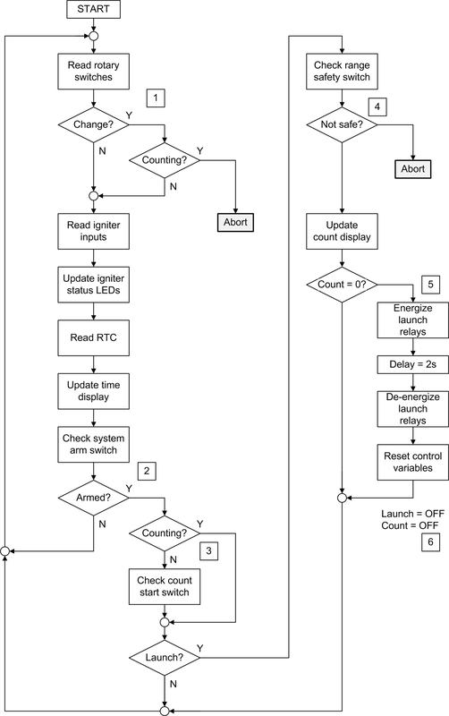
Figure 13-12 shows the actions encompassed by the main loop.
At reference 1 in the diagram the loop starts by reading the rotary switches (igniter select and count time select). If the count time has changed since the last time the switch was read and the count is active (i.e., a launch is in progress), then the launcher will stop the count, disarm the system, and enter an abort state.
At reference 2 the software looks at the arm switch. If the switch was off in the previous iteration of the loop but is now on, then the system arm flag is set and the master launch power relay (see Figure 13-9) is energized. If the system arm flag is true, then we check to see if a count is in progress. If it is, then we don’t read the launch start switch (reference 3); otherwise, we see if the user has pressed the launch button. If so, then we set the launch state to true (on) and start the count.
The righthand side of Figure 13-12 is only active if the system is in the launch state and a count is in progress. At reference 4 a check is made to verify that the range safety switch is depressed (on). If not, then we abort the system and place it into a safe state.
Reference 5 is where the real action occurs. When the count reaches zero the launch relays corresponding to the select ignition circuits are energized. The relays are held in an on state for 2 seconds, and then released. This is likely not the optimal way to do this. It would be better to look at the igniter status and de-energize the relays once all the igniters are open. The time delay would be a maximum permissible time before declaring a fault.
At reference 6, either the launch has been a success or the rocket is still (hopefully) sitting on the pad. In any case, the system is restored to a standby state, the relays are powered off, and the master power relay is de-energized. I would also suggest disarming the system, so that the user must set the arm switch to off and then back to on to rearm the launcher.
Reading switch inputs, setting LED states, reading the RTC, and controlling the relays can take place very rapidly. It doesn’t look like interrupts will be necessary for this design. That being said, you might want to consider an interrupt for the range safety switch. This is why it was connected directly to the Mega2560 instead of through the I/O expander.
The range safety switch can be used to trigger an interrupt that will disengage the igniter power relay (relay 3, relay module 2) the instant that the switch is released. So even if the MCU takes a few tens of milliseconds to read the state of the switch and respond by putting the system into an abort state, the power will have already been cut to the rocket motor igniters.
The LCD can be used to display messages during the loop. It would be good to see the current state and get messages if a fault should occur. It would not be particularly useful to repeat the time or the count with the LCD. That would just add latency (i.e., execution delay) to the main loop.
When writing the software, the primary guide is the functional requirements. These are the things the software must support in order to meet the requirements, and consequently fulfill the objectives for the project. For examples of ways to arrange the software into modules, refer to Chapters Chapters 10, 11, and 12.
From Figure 13-12 we can see that there are multiple possibilities for additional modules. The igniter status read and update is one, as is the RTC and the time display update. The launch section of the loop (everything between reference 4 and reference 6) is another possible candidate for its own module. The RTC module, the LCD, the LED displays, and the I/O expander will most likely have classes defined, but there may not be much need to use classes for the main loop functions. They aren’t that complex, really.
Since this is a design analysis, not a full-on design, I will leave the software here. If you want to pursue this and create your own rocket launcher, then I would suggest that you look at the examples provided in the previous three chapters. With this design analysis as a starting point, you should not have too much difficulty working out the remaining details.
We can’t really define a time estimate because there’s no way to know who will be writing the software. Different people work at different rates; what might take one person an hour or so to code up could take another person half a day. So, to get some idea of how much effort the software may require, I recommend that you try writing some test code with a breadboard or undedicated prototype fixture (as seen in earlier chapters) to do something with the RTC or the LCD. Once you have a general idea of how long this takes, then you can multiply that by the number of unique functions in the software design, and then multiply that number by two. That might end up being close to how long it will really take, and if the software gets done before that, then all the better.
Testing and Operation
A test plan is always a good idea. Fortunately the launcher is relatively easy to test, as it is basically just switch inputs and relay outputs. You can simulate igniter continuity by simply connecting a jumper between the pairs of igniter output binding posts, and an open circuit is just the lack of a jumper.
If you look over the functional requirements you can see that they are all verifiable. In other words, if you rotate the igniter circuit select knob you should see the active LEDs light up in succession from 1 to 6. If the binding posts are connected to simulate igniters, the “ICC GO” light should also be active. Arm the system and then press and hold the range safety switch, and you should see the “Safety GO” light come on. If you start the count and then disconnect any of the active igniters, change the number of igniter circuits or the count time in mid-count, or release the range safety switch, the system should halt the count and go into an abort state.
Be careful not to let the count reach zero if you are using jumpers on the binding posts to simulate igniters. When the relays close, full current from the battery will flow through the jumpers. This could melt the jumper wires or damage the relays, or both. A better testing approach would be to use replaceable fuses or even actual igniters mounted on a wood base. You might also be able to use small incandescent bulbs with a correct voltage rating, provided that they have a sufficiently low cold (unlit) resistance. A typical igniter is about 0.5 ohms.
Cost Analysis
The final cost of the launcher depends on where you get the parts, and if you can find bargains. A major cost item is the chassis, which can run upwards of $30. You could elect to build a console from 1 by 1 inch (2.5 by 2.5 cm) hardwood and 1/4 inch (0.6 cm) fiberboard, but that is assuming that you have the necessary woodworking tools. After purchasing the materials and adding in your time, you may find that it’s more cost-effective to just buy the chassis.
Based on the final parts list in Table 13-5, the total cost for the Phase I version will likely be somewhere around $125, give or take $25. The Phase II features could easily drive the cost up to well over $300, but you could likely hold this down by doing some smart shopping and bargain hunting.
..................Content has been hidden....................
You can't read the all page of ebook, please click here login for view all page.