16
Wireless Data
In this chapter, you’ll learn how to send and receive instructions and data using various types of wireless transmission hardware. Specifically, you’ll learn how to
- Send digital output signals using low-cost wireless modules
- Create a simple and inexpensive wireless remote control system
- Use LoRa wireless data receivers and transceivers
- Create a remote control temperature sensor
Using Low-Cost Wireless Modules
It’s easy to send text information in one direction using a wireless link between two Arduino-controlled systems that have inexpensive radio frequency (RF) data modules, such as the transmitter and receiver modules shown in Figure 16-1. These modules are usually sold in pairs and are known as RF Link modules or kits. Good examples are part 44910433 from PMD Way or parts WRL-10534 and WRL-10532 from SparkFun. We’ll use the most common module types that run on the 433 MHz radio frequency in our projects.
The connections shown at the bottom of the transmitter in Figure 16-2 are, from left to right, data in, 5 V, and GND. A connection for an external antenna is at the top-right corner of the board. The antenna can be a single length of wire, or it can be omitted entirely for short transmission distances. (Each brand of module can vary slightly, so check the connections on your particular device before moving forward.)
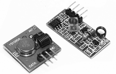
Figure 16-1: RF Link transmitter and receiver set

Figure 16-2: Transmitter RF Link module
Figure 16-3 shows the receiver module, which is slightly larger than the transmitter module.

Figure 16-3: Receiver RF Link module
The connections on the receiver are straightforward: the V+ and V− pins connect to 5 V and GND, respectively, and DATA connects to the Arduino pin allocated to receive the data. These pins are usually labeled on the other side of the module. If they’re not labeled or you’re not sure, look for the module’s data sheet or contact the supplier.
Before you can use these modules, you also need to download and install the latest version of the VirtualWire library from http://www.airspayce.com/mikem/arduino/VirtualWire/ using the method described in Chapter 7. This library is also included with the sketch download file for this book, which is available at https://nostarch.com/arduino-workshop-2nd-edition/. After you’ve installed the library, you’ll be ready to move on to the next section.
Project #46: Creating a Wireless Remote Control
We’ll remotely control two digital outputs: you’ll press buttons connected to one Arduino board to control matching digital output pins on another Arduino located some distance away. This project will show you how to use the RF Link modules. You’ll also learn how to determine how far away you can be and remotely control the Arduino. It’s important to know this before you commit to using the modules for more complex tasks. (In open air, the distance you can achieve is generally about 100 meters, but the distance will be less when you are indoors or when the modules are separated by obstacles.)
The Transmitter Circuit Hardware
The following hardware is required for the transmitter circuit:
- Arduino and USB cable
- AA battery holder and wiring (as used in Chapter 14)
- One 433 MHz RF Link transmitter module
- Two 10 kΩ resistors (R1 and R2)
- Two 100 nF capacitors (C1 and C2)
- Two push buttons
- One breadboard
The Transmitter Schematic
The transmitter circuit consists of two push buttons with debounce circuitry connected to digital pins 2 and 3, as well as the transmitter module wired as described earlier (Figure 16-4).

Figure 16-4: Transmitter schematic for Project 46
The Receiver Circuit Hardware
The following hardware is required for the receiver circuit:
- Arduino and USB cable
- AA battery holder and wiring (as used in Chapter 14)
- One 433 MHz RF Link receiver module
- One breadboard
- Two LEDs of your choice
- Two 560 Ω resistors (R1 and R2)
The Receiver Schematic
The receiver circuit consists of two LEDs on digital pins 6 and 7 and the data pin from the RF Link receiver module connected to digital pin 8, as shown in Figure 16-5.

Figure 16-5: Receiver schematic for Project 46
You can substitute the breadboard, LEDs, resistors, and receiver module with a Freetronics 433 MHz receiver shield, shown in Figure 16-6.

Figure 16-6: A Freetronics 433 MHz receiver shield
The Transmitter Sketch
Now let’s examine the sketch for the transmitter. Enter and upload the following sketch to the Arduino with the transmitter circuit:
// Project 46 - Creating a Wireless Remote Control, Transmitter Sketch

1 #include <VirtualWire.h>
uint8_t buf[VW_MAX_MESSAGE_LEN];
uint8_t buflen = VW_MAX_MESSAGE_LEN;

2 const char *on2 = "a";
const char *off2 = "b";
const char *on3 = "c";
const char *off3 = "d";

void setup()
{
3     vw_set_ptt_inverted(true);      // Required for RF Link modules
    vw_setup(300);                  // set data speed
4     vw_set_tx_pin(8);
    pinMode(2, INPUT);
    pinMode(3, INPUT);
}

void loop()
{
5   if (digitalRead(2)==HIGH)
  {
       vw_send((uint8_t *)on2, strlen(on2));  // send data out to the world
       vw_wait_tx();                          // wait a moment
       delay(200);
  }
  if (digitalRead(2)==LOW)
  {
6        vw_send((uint8_t *)off2, strlen(off2));
       vw_wait_tx();
       delay(200);
  }
  if (digitalRead(3)==HIGH)
  {
       vw_send((uint8_t *)on3, strlen(on3));
       vw_wait_tx();
       delay(200);
  }
  if (digitalRead(3)==LOW)
  {
       vw_send((uint8_t *)off3, strlen(off3));
       vw_wait_tx();
       delay(200);
  }
}
We include the VirtualWire library at 1 and use its functions at 3 to set up the RF Link transmitter module and set the data speed. At 4, we set digital pin 8, which is used to connect the Arduino to the data pin of the transmitter module and to control the speed of the data transmission. (You can use any other digital pins if necessary, except 0 and 1, which would interfere with the serial line.)
The transmitter sketch reads the status of the two buttons connected to digital pins 2 and 3 and sends a single text character to the RF Link module that matches the state of the buttons. For example, when the button on digital pin 2 is HIGH, the Arduino sends the character a, and when the button is LOW, it sends the character b. When the button on digital pin 3 is HIGH, the Arduino sends the character c, and when the button is LOW, it sends the character d. The four states are declared starting at 2.
The transmission of the text character is handled using one of the four sections’ if statements, starting at 5—for example, the contents of the if-then statement at 6. The variable transmitted is used twice, as shown here with on2, for example:
vw_send((uint8_t *)on2, strlen(on2)); The function vw_send() sends the contents of the variable on2, but it needs to know the length of the variable in characters, so we use strlen() to accomplish this.
The Receiver Sketch
Now let’s add the receiver sketch. Enter and upload the following sketch to the Arduino with the receiver circuit:
// Project 46 - Creating a Wireless Remote Control, Receiver Sketch
#include <VirtualWire.h>

uint8_t buf[VW_MAX_MESSAGE_LEN];
uint8_t buflen = VW_MAX_MESSAGE_LEN;

void setup()
{
1   vw_set_ptt_inverted(true);    // Required for RF Link modules
  vw_setup(300);
2   vw_set_rx_pin(8);
  vw_rx_start();
  pinMode(6, OUTPUT);
  pinMode(7, OUTPUT);
}

void loop()
{
3   if (vw_get_message(buf, &buflen))
  {
4     switch(buf[0])
    {
      case 'a':
      digitalWrite(6, HIGH);
      break;
      case 'b':
      digitalWrite(6, LOW);
      break;
      case 'c':
      digitalWrite(7, HIGH);
      break;
      case 'd':
      digitalWrite(7, LOW);
      break;
    }
  }
}
As with the transmitter circuit, we use the VirtualWire functions at 1 to set up the RF Link receiver module and set the data speed. At 2 we set the Arduino digital pin to which the link’s data output pin is connected (pin 8).
When the sketch is running, the characters sent from the transmitter circuit are received by the RF Link module and sent to the Arduino. The function vw_get_message() at 3 takes the characters received by the Arduino, which are interpreted by the switch case statement at 4. For example, pressing button S1 on the transmitter circuit will send the character a. This character is received by the transmitter, which sets digital pin 6 to HIGH, turning on the LED.
You can use this simple pair of demonstration circuits to create more complex controls for Arduino systems by sending codes as basic characters to be interpreted by a receiver circuit.
Using LoRa Wireless Data Modules for Greater Range and Faster Speed
When you need a wireless data link with greater range and a faster data speed than what the basic wireless modules used earlier can provide, LoRa data modules may be the right choice. LoRa is short for “long range,” and these modules work at long range with low power consumption. The modules are transceivers, which are devices that can both transmit and receive data, so you don’t need a separate transmitter and receiver. A further benefit of using LoRa modules is that different types of modules can communicate, allowing you, the designer, to create control and data networks that range from the simple to the complex. In this chapter, you will create several basic modules that can be built upon for various purposes.

Figure 16-7: A LoRa shield for Arduino
For convenience, we’ll be using two LoRa shields for Arduino, such as PMD Way part number 14290433, shown in Figure 16-7.
When purchasing your LoRa shields, you will need to select an operating frequency. The correct frequency will vary depending on your country of use. This is to ensure that your data transmissions don’t interfere with other devices in your area. LoRa products are available in three operating frequency bands:
- 433 MHz Used in United States and Canada
- 868 MHz Used in United Kingdom and Europe
- 915 MHz Used in Australia and New Zealand
You can find a full list of countries and the frequency ranges you need to use in each at https://www.thethingsnetwork.org/docs/lorawan/frequencies-by-country.html.
Finally, you need to download and install the Arduino library, which can be found at https://github.com/sandeepmistry/arduino-LoRa/archive/master.zip.
Project #47: Remote Control over LoRa Wireless
This project will demonstrate simple data transmission from one LoRA-equipped Arduino to another to allow remote control of a digital output pin. Our transmitter has two buttons to turn the receiver circuit’s output pin on and off.
The Transmitter Circuit Hardware
The following hardware is required for the transmitter circuit:
- Arduino and USB cable
- LoRa shield for Arduino
- Two 10 kΩ resistors (R1 and R2)
- Two 100 nF capacitors (C1 and C2)
- Two push buttons
- AA battery holder and wiring (as used in Chapter 14)
The Transmitter Schematic
The transmitter circuit, as shown in Figure 16-8, consists of two push buttons with debounce circuitry connected to digital pins 2 and 3. The LoRa shield is placed on the Arduino Uno. Once the sketch has been uploaded, power is provided by the AA battery holder and wiring.

Figure 16-8: Transmitter schematic for Project 47
Before using your LoRa shield, there are three header jumpers, shown in Figure 16-9, that need to be removed from the shield. If you don’t remove them, they will interfere with other digital pins. You can remove them completely or just connect the headers to one of the two pins.

Figure 16-9: Header jumpers to remove from the LoRa shield
The Receiver Circuit Hardware
The following hardware is required for the receiver circuit:
- Arduino and USB cable
- LoRa shield for Arduino
- One LED
- One 560 Ω resistor (R1)
The Receiver Schematic
The receiver circuit, shown in Figure 16-10, consists of one LED and a current-limiting resistor connected between digital pin 7 and GND. We leave this connected to the PC via USB, so no external power is required.

Figure 16-10: Receiver schematic for Project 47
The Transmitter Sketch
Now let’s examine the sketch for the transmitter. Enter and upload the following sketch to the Arduino with the transmitter circuit:
// Project 47 - Remote Control over LoRa Wireless, Transmitter Sketch
1 #define LORAFREQ (915000000L)
2 #include <LoRa.h>
#include <SPI.h>
3 void loraSend(int controlCode)
{
4   LoRa.beginPacket();      // start sending data
  LoRa.print("ABC");       // "ABC" is our three-character code for receiver
  LoRa.print(controlCode); // send our instructions (controlCode codes)
5   LoRa.endPacket();        // finished sending data
5   LoRa.receive();          // start listening
}
void setup()
{
  pinMode(4, INPUT);    // on button
  pinMode(3, INPUT);    // off button
6   LoRa.begin(LORAFREQ); // start up LoRa at specified frequency
}
void loop()
{
  // check for button presses to control receiver
  if (digitalRead(4) == HIGH)
  {
    loraSend(1); // '1' is code for turn receiver digital pin 5 HIGH
    delay(500);  // allow time to send
  }
  if (digitalRead(3) == HIGH)
  {
    loraSend(0); // '0' is code for turn receiver digital pin 5 LOW
    delay(500);  // allow time to send
  }
}
The operating frequency is selected at 1. Our example is using 915 MHz, so you may need to change this to either 433000000L or 868000000L depending on your country and shield. We include the Arduino LoRa library at 2, and it’s activated at 4. The SPI library is also included, as the LoRa shield uses the SPI bus to communicate with the Arduino. At 6, the LoRa transceiver is activated at the appropriate frequency, after the digital pins are prepared to be inputs for the buttons.
At 3, we have the custom function loraSend(int controlCode). This is called when a button is pressed. It first sends a three-character code—in this case ABC—out on the LoRa airwaves, followed by a control code. The character code allows you to direct the control to a particular receiver circuit. Otherwise, if you’re using two or more receivers, there would be confusion as to which one would be controlled by the transmitter. You will see that the receiver will act only if ABC is sent. The control codes in our example are 1 and 0 (to turn the receiver’s digital output on or off, respectively).
At 4, the LoRa module is switched to transmit mode, and then the character and control codes are sent over the airwaves. At 5, the LoRa module is told to stop transmitting and gets switched back to receiving data. Once you have uploaded the transmitter sketch, the transmitter hardware can be disconnected from the computer and powered using the battery pack.
The Receiver Sketch
Now let’s examine the receiver sketch. Enter and upload the following sketch to the Arduino with the receiver circuit:
// Project 47 - Remote Control over LoRa Wireless, Receiver Sketch
1 #define LORAFREQ (915000000L)
2 #include <LoRa.h>
#include <SPI.h>
void takeAction(int packetSize)
// things to do when data received over LoRa wireless
{
3   char incoming[4] = "";
  int k;
  for (int i = 0; i < packetSize; i++)
  {
    k = i;
    if (k > 6)
    {
      k = 6; // make sure we don't write past end of string
    }
    incoming[k] = (char)LoRa.read();
4   }
  // check the three-character code sent from transmitter is correct
5   if (incoming[0] != 'A')
  {
    return; // if not 'A', stop function and go back to void loop()
  }
5   if (incoming[1] != 'B')
  {
    return; // if not 'B', stop function and go back to void loop()
  }
5   if (incoming[2] != 'C')
  {
    return; // if not 'C', stop function and go back to void loop()
  }
  // If made it this far, correct code has been received from transmitter.
  // Now to do something...
  if (incoming[3] == '1')
  {
    digitalWrite(7, HIGH);
  }
  if (incoming[3] == '0')
  {
    digitalWrite(7, LOW);
  }
}

void setup()
{
  pinMode(7, OUTPUT);
6   LoRa.begin(LORAFREQ);       // start up LoRa at specified frequency
7   LoRa.onReceive(takeAction); // call function "takeAction" when data received
8   LoRa.receive();             // start receiving
}
void loop()
{
}
Once again we include the Arduino LoRa library at 2, and it’s activated at 6. The operating frequency is also selected at 1. Our example is using 915 MHz, so you may need to change this to either 433000000L or 868000000L depending on your country and shield. The SPI library is also included, as the LoRa shield uses the SPI bus to communicate with the Arduino. At 7, we tell the sketch to run a certain function—in this case void takeAction()—when data is received over the airwaves. Then at 8, the LoRa module is switched to receive mode.
When operating, the receiver simply waits for data to be received by the LoRa module. At that point, the function takeAction() is called. This takes each character of data from the transmitter and places it into an array of characters called incoming[4] between 3 and 4. Next, the receiver checks each character of the code (in our case ABC) at 5 to ensure the transmission is for this particular receiver. Finally, if this is successful, the control character is checked. If it’s a 1, digital pin 7 is set to HIGH, and if it’s a 0, digital pin 7 is set to LOW.
Now you have the basic framework for a longer-distance remote control. Furthermore, by assigning different character codes to multiple receivers, you can expand your system to control more than one receiver unit from one transmitter.
However, for serious applications, you may want confirmation that an instruction from the transmitter has been successfully completed by the receiver, so we’ll add a confirmation function in the next project.
Project #48: Remote Control over LoRa Wireless with Confirmation
This project adds a confirmation system to the receiver-transmitter setup created in Project 47, creating a two-way data system. An LED on the transmitter circuit will turn on when the receiver output is set to HIGH and turn off when the receiver output is set to LOW.
The Transmitter Circuit Hardware
The following hardware is required for the transmitter circuit:
- Arduino and USB cable
- LoRa Shield for Arduino
- Two 10 kΩ resistors (R1 and R2)
- One 560 Ω resistor (R3)
- One LED
- Two 100 nF capacitors (C1 and C2)
- Two push buttons
- AA battery holder and wiring (as used in Chapter 14)
The Transmitter Schematic
The transmitter circuit, shown in Figure 16-11, consists of two push buttons with debounce circuitry connected to digital pins 3 and 4, and an LED and current-limiting resistor on digital pin 6. The LoRa shield is placed on the Arduino Uno. Once the sketch has been uploaded, power is provided by the AA battery holder and wiring.

Figure 16-11: Transmitter schematic for Project 48
The receiver circuit and schematic for this project are identical to those used for Project 47.
The Transmitter Sketch
Now let’s examine the sketch for the transmitter. Enter and upload the following sketch to the Arduino with the transmitter circuit:
// Project 48 - Remote Control over LoRa Wireless with Confirmation,
// Transmitter Sketch
#define LORAFREQ (915000000L)
#include <SPI.h>
#include <LoRa.h>
void loraSend(int controlCode)
{
  LoRa.beginPacket(); // start sending data
  LoRa.print("DEF");  // "DEF" is our three-character code for the receiver.
                      // Needs to be matched on RX.
  LoRa.print(controlCode); // send our instructions (controlCode codes)
  LoRa.endPacket();   // finished sending data
  LoRa.receive();     // start listening
}
1 void takeAction(int packetSize)
// things to do when data received over LoRa wireless
{
  char incoming[4] = "";
  int k;
  for (int i = 0; i < packetSize; i++)
  {
    k = i;
    if (k > 6)
    {
      k = 18; // make sure we don't write past end of string
    }
    incoming[k] = (char)LoRa.read();
  }
  // check the three-character code sent from receiver is correct
  if (incoming[0] != 'D')
  {
    return; // if not 'D', stop function and go back to void loop()
  }
  if (incoming[1] != 'E')
  {
    return; // if not 'E', stop function and go back to void loop()
  }
  if (incoming[2] != 'F')
  {
    return; // if not 'F', stop function and go back to void loop()
  }
  // If made it this far, correct code has been received from receiver.
  // Now to do something...
2   if (incoming[3] == '1')
  {
    digitalWrite(6, HIGH);
    // receiver has turned output on and has sent a signal confirming this
  }
2   if (incoming[3] == '0')
  {
    digitalWrite(6, LOW);
    // receiver has turned output off and has sent a signal confirming this
  }
}
void setup()
{
  pinMode(4, INPUT);          // on button
  pinMode(3, INPUT);          // off button
  pinMode(6, OUTPUT);         // status LED
  LoRa.begin(LORAFREQ);       // start up LoRa at specified frequency
  LoRa.onReceive(takeAction); // call function "takeAction" when data received
                              // over LoRa wireless
}
void loop()
{
  // check for button presses to control receiver
  if (digitalRead(4) == HIGH)
  {
    loraSend(1); // '1' is code for turn receiver digital pin 7 HIGH
    delay(500);  // button debounce
  }
  if (digitalRead(3) == HIGH)
  {
    loraSend(0); // '0' is code for turn receiver digital pin 7 LOW
    delay(500);  // button debounce
  }
}
Our transmitter circuit operates in the same way as in Project 47, by first sending a character code for identification and then a control code to turn the receiver’s output on or off. In this project, however, the transmitter listens for a signal from the receiver, and once the receiver has completed the control instruction from the transmitter, the receiver sends a character code and control code back to the transmitter.
So at 1, we have a new function, takeAction(), that checks for the character code DEF from the receiver circuit. The receiver then sends a 1 if it has turned on its output pin or a 0 if the output has been turned off. Our transmitter circuit can then display this status by controlling the LED on digital pin 6 via the code at 2.
The Receiver Sketch
Finally, let’s examine the sketch for the receiver. Enter and upload the following sketch to the Arduino with the receiver circuit:
// Project 48 - Remote Control over LoRa Wireless with Confirmation, Receiver
// Sketch
#define LORAFREQ (915000000L)
#include <SPI.h>
#include <LoRa.h>
void loraSend(int controlCode)
{
  LoRa.beginPacket();      // start sending data
  LoRa.print("DEF");       // "DEF" is our three-character code for the
                           // transmitter
  LoRa.print(controlCode); // send our instructions (controlCode codes)
  LoRa.endPacket();        // finished sending data
  LoRa.receive();          // start listening
}
void takeAction(int packetSize)
// things to do when data received over LoRa wireless
{
  char incoming[4] = "";
  int k;
  for (int i = 0; i < packetSize; i++)
  {
    k = i;
    if (k > 6)
    {
      k = 18; // make sure we don't write past end of string
    }
    incoming[k] = (char)LoRa.read();
  }
  // check the three-character code sent from transmitter is correct
  if (incoming[0] != 'A')
  {
    return; // if not 'A', stop function and go back to void loop()
  }
  if (incoming[1] != 'B')
  {
    return; // if not 'B', stop function and go back to void loop()
  }
  if (incoming[2] != 'C')
  {
    return; // if not 'C', stop function and go back to void loop()
  }
  // If made it this far, correct code has been received from transmitter.
  // Now to do something...
  if (incoming[3] == '1')
  {
    digitalWrite(7, HIGH);
1     loraSend(1); // tell the transmitter that the output has been turned on
  }
  if (incoming[3] == '0')
  {
    digitalWrite(7, LOW);
1     loraSend(0); // tell the transmitter that the output has been turned off
  }
}
void setup()
{
  pinMode(7, OUTPUT);
  LoRa.begin(LORAFREQ);       // start up LoRa at specified frequency
  LoRa.onReceive(takeAction); // call function "takeAction" when data received
                              // over LoRa wireless
  LoRa.receive(); // start receiving
}
void loop()
{
}
Our receiver operates in the same manner as the one for Project 47, except in this case, the receiver sends back the character code DEF to the transmitter, followed by a 1 or a 0 to indicate that the output pin has been turned on or off. This is done at 1 using the loraSend() function.
At this point, you have two example projects that show how you can not only control digital output pins wirelessly across a greater distance than with the earlier projects but also confirm that the actions have taken place. You can now expand on these examples to create your own remote-control projects. But next, we’ll experiment with sending sensor data over a LoRa wireless link with Project 49.
Project #49: Sending Remote Sensor Data Using LoRa Wireless
This project builds on our previous efforts by using your computer to request temperature data from a remote sensor.
The Transmitter Circuit Hardware
The following hardware is required for the transmitter circuit:
- Arduino and USB cable
- LoRa shield for Arduino
This project uses the Serial Monitor on your PC for control, so the transmitter circuit is simply the Arduino and LoRa shield connected to the PC via the USB cable.
The Receiver Circuit Hardware
The following hardware is required for the receiver circuit:
- Arduino and USB cable
- LoRa shield for Arduino
- TMP36 temperature sensor
- Solderless breadboard
- External power for Arduino
- Male-to-male jumper wires
The Receiver Schematic
Our circuit is simply the TMP36 temperature sensor connected to analog pin A0, along with the LoRa shield placed on the Arduino, as shown in Figure 16-12.

Figure 16-12: Receiver schematic for Project 49
The receiver circuit may be some distance from the computer, so you can harness a USB power supply or the battery solution used in earlier projects.
The Transmitter Sketch
Now let’s examine the sketch for the transmitter. Enter and upload the following sketch to the Arduino with the transmitter circuit:
// Project 49 - Sending Remote Sensor Data Using LoRa Wireless, Transmitter
// Sketch
#define LORAFREQ (915000000L)
#include <SPI.h>
#include <LoRa.h>
char command;
void loraSend(int controlCode)
{
  LoRa.beginPacket();      // start sending data
1   LoRa.print("ABC");       // "ABC" is our three-character code for the
                           // transmitter
  LoRa.print(controlCode); // send our instructions (controlCode codes)
  LoRa.endPacket();        // finished sending data
  LoRa.receive();          // start listening
}
void takeAction(int packetSize)
// send text received from sensor Arduino via LoRa to Serial Monitor
{
  char incoming[31] = "";
  int k;
  for (int i = 0; i < packetSize; i++)
  {
    k = i;
    if (k > 31)
    {
      k = 31; // make sure we don't write past end of string
    }
    incoming[k] = (char)LoRa.read();
    Serial.print(incoming[k]); // display temp information from sensor board
  }
  Serial.println();
}
void setup()
{
2   LoRa.begin(LORAFREQ);       // start up LoRa at specified frequency
  LoRa.onReceive(takeAction); // call function "takeAction" when data received
                              // over LoRa wireless
  LoRa.receive();             // start receiving
  Serial.begin(9600);
}
void loop()
{
3   Serial.print("Enter 1 for Celsius or 2 for Fahrenheit then Enter: ");
  Serial.flush(); // clear any "junk" out of the serial buffer before waiting
4   while (Serial.available() == 0)
  {
    // do nothing until something enters the serial buffer
  }
  while (Serial.available() > 0)
  {
    command = Serial.read() - '0';
    // read the number in the serial buffer,
    // remove the ASCII text offset for zero: '0'
  }
  Serial.println();
5   loraSend(command);
  delay(2000);
}
As with the earlier projects in this chapter, we initialize the LoRa hardware and the Serial Monitor at 2. However, instead of hardware buttons, we use the Serial Monitor to accept commands from the user and send those to the receiver hardware. In this project, the user is prompted to enter 1 or 2 in the Serial Monitor’s input box to retrieve the temperature from the receiver hardware in Celsius or Fahrenheit, respectively. This happens at 3. The computer waits for user input at 4, then sends out either command to the receiver hardware via loraSend() at 5. Again, we use a three-character code to keep the transmission exclusively for the receiver board at 1.
The Receiver Sketch
Now let’s examine the sketch for the receiver. Enter and upload the following sketch to the Arduino with the receiver circuit:
// Project 49 - Sending Remote Sensor Data Using LoRa Wireless, Receiver
// Sketch
#define LORAFREQ (915000000L)
#include <SPI.h>
#include <LoRa.h>

float sensor = 0;
float voltage = 0;
float celsius = 0;
float fahrenheit = 0;

void loraSendC()
{
  LoRa.beginPacket(); // start sending data
  sensor = analogRead(0);
  voltage = ((sensor * 5000) / 1024);
  voltage = voltage - 500;
  celsius = voltage / 10;
  fahrenheit = ((celsius * 1.8) + 32);
1   LoRa.print("Temperature: ");
  LoRa.print(celsius, 2);
  LoRa.print(" degrees C");
2   LoRa.endPacket(); // finished sending data
  LoRa.receive();   // start listening
}

void loraSendF()
// send temperature in Fahrenheit
{
  LoRa.beginPacket(); // start sending data
  sensor = analogRead(0);
  voltage = ((sensor * 5000) / 1024);
  voltage = voltage - 500;
  celsius = voltage / 10;
  fahrenheit = ((celsius * 1.8) + 32);
1   LoRa.print("Temperature: ");
  LoRa.print(fahrenheit, 2);
  LoRa.print(" degrees F");
2   LoRa.endPacket(); // finished sending data
  LoRa.receive();   // start listening
}
void takeAction(int packetSize)
// things to do when data received over LoRa wireless
{
  char incoming[6] = "";
  int k;
  for (int i = 0; i < packetSize; i++)
  {
    k = i;
    if (k > 6)
    {
      k = 6; // make sure we don't write past end of string
    }
    incoming[k] = (char)LoRa.read();
  }
3   // check the three-character code sent from transmitter is correct
  if (incoming[0] != 'A')
  {
    return; // if not 'A', stop function and go back to void loop()
  }
  if (incoming[1] != 'B')
  {
    return; // if not 'B', stop function and go back to void loop()
  }
  if (incoming[2] != 'C')
  {
    return; // if not 'C', stop function and go back to void loop()
  }
  // If made it this far, correct code has been received from transmitter
  if (incoming[3] == '1')
  {
4     loraSendC();
  }
  if (incoming[3] == '2')
  {
5     loraSendF();
  }
}
void setup()
{
  LoRa.begin(LORAFREQ);       // start up LoRa at specified frequency
  LoRa.onReceive(takeAction); // call function "takeAction" when data received
  LoRa.receive();             // start receiving
}
void loop()
{
}
Using the same method as in Project 48, our receiver hardware decodes the transmission from the transmitter to ensure the data is meant for it by checking the character code sent at 3. If this is correct, the receiver board calls one of either loraSendC() or loraSendF() at 4 or 5, respectively. Those two functions calculate the temperature from the TMP36 sensor and, between 1 and 2, send a string of text back to the transmitter board containing the temperature and measurement type.
Once you have assembled the hardware for both circuits and uploaded both sketches, place the powered receiver circuit (with the sensor) where you’d like to measure temperature from your computer. Ensure the transmitter circuit is connected to the computer. Open the Serial Monitor in the IDE and follow the instructions to check the temperature. An example is shown in Figure 16-13.

Figure 16-13: Example output for Project 49
Looking Ahead
This chapter showed how simple it is to control multi-Arduino systems remotely. For example, you can control digital outputs by sending characters from one Arduino to another, and you can use LoRa wireless technology to create more complex, multi-Arduino control systems that include data return. With the knowledge you’ve gained so far, many creative options are available to you.
But there’s still much more to investigate in terms of wireless data transmission, so keep reading and working along with the examples as you learn to use simple television remote controls with the Arduino in the next chapter.