22
Cellular Communications
In this chapter you will
- Have your Arduino dial a telephone number when an event occurs
- Send a text message to a cell phone using the Arduino
- Control devices connected to an Arduino via text message from a cell phone
You can connect your Arduino projects to a cell phone network to allow simple communication between your Arduino and a cellular or landline phone. With a little imagination, you can come up with many uses for this type of communication, including some of the projects included in this chapter.
Be sure to review this chapter before you purchase any hardware, because the success of the projects will depend on your cellular network. Your network must be able to do the following:
- Operate at UMTS (3G) 850 MHz, 900 MHz, 1900 MHz, or 2100 MHz.
- Allow the use of devices not supplied by the network provider.
To make use of these projects, you might consider selecting either a prepaid calling plan or a plan that offers a lot of included text messages, in case an error in your sketch causes the project to send out several SMS (Short Message Service) text messages. Also, make sure the requirement to enter a PIN to use the SIM card is turned off. (You should be able to do this easily by inserting the SIM card in a regular cell phone and changing the setting in the security menu.)
The Hardware
All the projects use a common hardware configuration, so we’ll set that up first. You’ll need specific hardware to complete the projects in this chapter, starting with a SIM5320-type 3G GSM shield and antenna, shown in Figure 22-1. This shield is available from TinySine (https://www.tinyosshop.com/) and its distributors. There are two types of SIM5320 shield: the SIM5320A and SIM5320E.
The -E version uses the UMTS/HSDPA 900/2100 MHz frequency bands (mainly for European users), and the -A version uses the UMTS/HSDPA 850/1900 MHz frequency band (mainly for US-based users and Australians using the Telstra network).

Figure 22-1: 3G shield with antenna attached
You’ll also need a power supply. In some situations, the 3G shield can draw up to 2 A of current (more than is available from the Arduino) and will damage your Arduino if it’s used without external power. Therefore, you will need an external power supply. This can be a DC plug pack or wall wart power supply brick (or a large 7.2 V rechargeable battery, solar panel/battery source, 12 V battery, or similar, as long as it doesn’t exceed 12 V DC) that can offer up to 2 A of current.
Hardware Configuration and Testing
Now let’s configure and test the hardware by making sure that the 3G shield can communicate with the cellular network and the Arduino. We first need to set up the serial communication jumpers, since the 3G shield communicates with the Arduino via a serial port in the same manner as the GPS modules used in Chapter 15. We can set which digital pins the shield will use to communicate with the Arduino using jumpers on the top right of the shield. All our projects will use digital pin 2 for shield transmit and digital pin 3 for shield receive. To configure this, connect jumpers over the TX2 and RX3 pins, as shown in Figure 22-2.

Figure 22-2: Shield serial configuration jumpers
Next, turn the shield over and insert your SIM card into the holder, as shown in Figure 22-3.

Figure 22-3: SIM card in place
Next, gently insert the 3G shield into the Arduino. Connect the external power and the USB cable between the Arduino and the PC. Finally, just as with a cellular phone, you need to turn the SIM module on (and off) using the power button on the top-left corner of the shield, as shown in Figure 22-4. Press the button for 2 seconds and let go. After a moment, the P (for power) and S (for status) LEDs will come on, and the blue LED will start blinking once the 3G shield has registered with the cellular network.
For future reference, the shield’s power button is connected to digital pin 8, so you can control the power from your sketch instead of manually turning the button on or off.
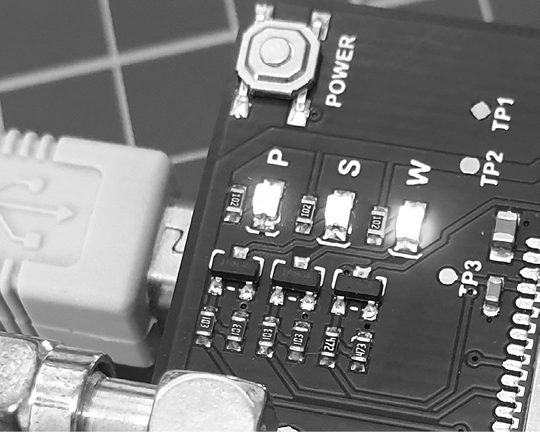
Figure 22-4: 3G shield power button and status LEDs
Now enter and upload the sketch shown in Listing 22-1.
// Listing 22-1

1 #include <SoftwareSerial.h> // Virtual serial port
2 SoftwareSerial cell(2,3);
char incoming_char = 0;

void setup()
{
  // Initialize serial ports for communication
  Serial.begin(9600);
3   cell.begin(4800);
  Serial.println("Starting SIM5320 communication...");
}

void loop()
{
  // If a character comes in from 3G shield
  if( cell.available() > 0 )
  {
    // Get the character from the cellular serial port
    incoming_char = cell.read();
    // Print the incoming character to the Serial Monitor
    Serial.print(incoming_char);
  }
  // If a character is coming from the terminal to the Arduino...
  if( Serial.available() > 0 )
  {
    incoming_char = Serial.read(); // Get the character from the terminal
    cell.print(incoming_char); // Send the character to the cellular module
  }
}
Listing 22-1: 3G shield test sketch
This sketch simply relays all the information coming from the 3G shield to the Serial Monitor. The 3G shield has a software serial connection between it and Arduino digital pins 2 and 3 so that it won’t interfere with the normal serial connection between the Arduino and the PC, which is on digital pins 0 and 1. We set up a virtual serial port for the 3G shield at 1, 2, and 3. By default, the 3G shield communicates over serial at 4,800 bps, and this is fine for our projects.
Once you’ve uploaded the sketch, open the Serial Monitor window and wait about 10 seconds. Then, using a different telephone, call the number for your 3G shield. You should see data similar to that shown in Figure 22-5.

Figure 22-5: Example output from Listing 22-1
The RING notifications come from the shield when you are calling it, and the missed call notification shows up when you end the call to the shield. If your cellular network supports caller ID, the originating phone number is shown after the time. (The number has been blacked out in Figure 22-5 for the sake of privacy.) Now that the 3G shield is operating, we can make use of various functions for our projects.
Project #63: Building an Arduino Dialer
By the end of this project, your Arduino will dial a telephone number when an event occurs, as determined by your Arduino sketch. For example, if the temperature in your storage freezer rises above a certain level or your burglar alarm system activates, you could have the Arduino call you from a preset number, wait for 20 seconds, and then hang up. Your phone’s caller ID will identify the phone number as the Arduino.
The Hardware
This project uses the hardware described at the beginning of the chapter as well as any extra circuitry you choose for your application. For demonstration purposes, we’ll use a button to trigger the call.
In addition to the hardware already discussed, here’s what you’ll need to create this project:
- One push button
- One 10 kΩ resistor
- One 100 nF capacitor
- Various connecting wires
- One breadboard
The Schematic
Connect the external circuitry, as shown in Figure 22-6.

Figure 22-6: Schematic for Project 63
The Sketch
Enter but don’t upload the following sketch:
// Project 63 - Building an Arduino Dialer

#include <SoftwareSerial.h> // Virtual serial port
SoftwareSerial cell(2,3);
char incoming_char = 0;

void setup()
{
  pinMode(7, INPUT);        // for button
  pinMode(8, OUTPUT);       // shield power control
  // initialize serial ports for communication
  Serial.begin(9600);
  cell.begin(4800);
}

void callSomeone()
{
  // turn shield on
1   Serial.println("Turning shield power on...");
  digitalWrite(8, HIGH);
  delay(2000);
  digitalWrite(8, LOW);
  delay(10000);
2   cell.println("ATDxxxxxxxxxx"); // dial the phone number xxxxxxxxxx
  // change xxxxxxxxxx to your desired phone number (with area code)
  Serial.println("Calling ...");
  delay(20000);                  // wait 20 seconds
3   cell.println("ATH");           // end call
  Serial.println("Ending call, shield power off.");
  // turn shield off to conserve power
4   digitalWrite(8, HIGH);
  delay(2000);
  digitalWrite(8, LOW);
}
void loop()
{
5   if (digitalRead(7) == HIGH)
  {
6     callSomeone();
  }
}
Understanding the Sketch
After setting up the software serial and regular serial ports, the sketch waits for a press of the button connected to digital pin 7 at 5. Once it’s pressed, the function callSomeone() is run at 6. At 1, digital pin 8 is toggled HIGH for 2 seconds, turning the shield on, and waits 10 seconds to give the shield time to register with the cellular network. Next, at 2, the sketch sends the command to dial a telephone number. Finally, after the call has been ended at 3, the shield is turned off to conserve power at 4.
You’ll replace xxxxxxxxxx with the number you want your Arduino to call. Use the same dialing method that you’d use from your mobile phone. For example, if you wanted the Arduino to call 212.555.1212, you’d add this:
cell.println("ATD2125551212");After you have entered the phone number, you can upload the sketch, wait a minute to allow time for the 3G module to connect to the network, and then test it by pressing the button. It’s very easy to integrate the dialing function into an existing sketch, because it’s simply called when required at 2. From here, it’s up to you to find a reason—possibly triggered by a temperature sensor, a light sensor, or any other input reaching a certain level—for your Arduino to dial a phone number.
Now let’s drag your Arduino into the 21st century by sending a text message.
Project #64: Building an Arduino Texter
In this project, the Arduino will send a text message to another cell phone when an event occurs. To simplify the code, we’ll use the SerialGSM Arduino library, available from https://github.com/meirm/SerialGSM/archive/master.zip. After you’ve installed the library, restart the Arduino IDE.
The hardware you’ll need for this project is identical to that for Project 63.
The Sketch
Enter the following sketch into the Arduino IDE, but don’t upload it yet:
// Project 64 - Building an Arduino Texter
#include <SerialGSM.h>
#include <SoftwareSerial.h> // Virtual serial port
1 SerialGSM cell(2, 3);

void sendSMS()
{
2   cell.Message("The button has been pressed!");
  cell.SendSMS();
}

void setup()
{
  pinMode(7, INPUT);  // for button
  pinMode(8, OUTPUT); // shield power control
  // turn shield on
  Serial.println("Turning shield power on...");
  digitalWrite(8, HIGH);
  delay(2000);
  digitalWrite(8, LOW);
  // initialize serial ports for communication
  Serial.begin(9600);
  cell.begin(4800);
  cell.Verbose(true);
  cell.Boot();
  cell.FwdSMS2Serial();
3   cell.Rcpt("xxxxxxxxxxx");
  delay(10000);
}

void loop()
{
4   if (digitalRead(7) == HIGH)
  {
    sendSMS();
  }
}
Understanding the Sketch
The 3G shield is set up as normal at 1 and in void setup(). Button presses are detected at 4, and the function sendSMS() is called. This simple function sends a text message to the cell phone number stored at 3.
Before uploading the sketch, replace xxxxxxxxxxx with the recipient’s cell phone number; enter the area code plus number, without any spaces or brackets. For example, to send a text to 212.555.1212 in the United States, you would store 2125551212.

Figure 22-7: A sample text message being received
The text message to be sent is stored at 2. (Note that the maximum length for a message is 160 characters.)
After you have stored a sample text message and a destination number, upload the sketch, wait 30 seconds, and then press the button. In a moment, the message should arrive on the destination phone, as shown in Figure 22-7.
Project 64 can be integrated quite easily into other sketches, and various text messages could be sent by comparing data against a parameter with a switch case statement.
Project #65: Setting Up an SMS Remote Control
In this project, you’ll control the digital output pins on your Arduino by sending a text message from your cell phone. You should be able to use your existing knowledge to add various devices to control. We’ll allow for four separate digital outputs, but you can control more or fewer as required.
To turn on or off four digital outputs (pins 10 through 13 in this example), you’d send a text message to your Arduino in the following format: #axbxcxdx, replacing x with either a 0 for off or a 1 for on. For example, to turn on all four outputs, you’d send #a1b1c1d1.
The Hardware
This project uses the hardware described at the start of the chapter, plus any extra circuitry you choose. We’ll use four LEDs to indicate the status of the digital outputs being controlled. Therefore, the following extra hardware is required for this example:
- Four LEDs
- Four 560 Ω resistors
- Various connecting wires
- One breadboard
The Schematic
Connect the external circuitry as shown in Figure 22-8.
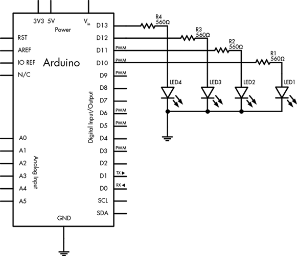
Figure 22-8: Schematic for Project 65
The Sketch
For this project, the 3G shield library is not used. Instead, we rely on the raw commands to control the module. Furthermore, we don’t turn the shield on or off during the sketch, as we need it to be on in order to listen for incoming text messages. Enter and upload the following sketch:
// Project 65 - Setting Up an SMS Remote Control
#include <SoftwareSerial.h>
SoftwareSerial cell(2,3);
char inchar;

void setup()
{
  // set up digital output pins to control
  pinMode(10, OUTPUT);
  pinMode(11, OUTPUT);
  pinMode(12, OUTPUT);
  pinMode(13, OUTPUT);
  digitalWrite(10, LOW); // default state for I/O pins at power-up or reset,
  digitalWrite(11, LOW); // change as you wish
  digitalWrite(12, LOW);
  digitalWrite(13, LOW);
  // initialize the 3G shield serial port for communication
  cell.begin(4800);
  delay(30000);
1   cell.println("AT+CMGF=1");
  delay(200);
2   cell.println("AT+CNMI=3,3,0,0");
  delay(200);
}

void loop()
{
  // if a character comes in from the cellular module...
3   if(cell.available() > 0)
  {
    inchar = cell.read();
4     if (inchar == '#') // the start of our command
    {
      delay(10);
      inchar = cell.read();
5       if (inchar == 'a')
      {
        delay(10);
        inchar = cell.read();
        if (inchar == '0')
        {
          digitalWrite(10, LOW);
        }
        else if (inchar == '1')
        {
          digitalWrite(10, HIGH);
        }
        delay(10);
        inchar = cell.read();
        if (inchar == 'b')
        {
          inchar = cell.read();
          if (inchar == '0')
          {
            digitalWrite(11, LOW);
          }
          else if (inchar == '1')
          {
            digitalWrite(11, HIGH);
          }
          delay(10);
          inchar = cell.read();
          if (inchar == 'c')
          {
            inchar = cell.read();
            if (inchar == '0')
            {
              digitalWrite(12, LOW);
            }
            else if (inchar == '1')
            {
              digitalWrite(12, HIGH);
            }
            delay(10);
            inchar = cell.read();
            if (inchar == 'd')
            {
              delay(10);
              inchar = cell.read();
              if (inchar == '0')
              {
                digitalWrite(13, LOW);
              }
              else if (inchar == '1')
              {
                digitalWrite(13, HIGH);
              }
              delay(10);
            }
          }
          cell.println("AT+CMGD=1,4"); // delete all SMS
        }
      }
    }
  }
}
Understanding the Sketch
In this project, the Arduino monitors every text character sent from the 3G shield. Thus, at 1, we tell the shield to convert incoming SMS messages to text and send the contents to the virtual serial port at 2. Next, the Arduino waits for a text message to come from the shield at 3.
Because the commands sent from the cell phone and passed by the 3G module to control pins on the Arduino start with a #, the sketch waits for a hash mark (#) to appear in the text message at 4. At 5, the first output parameter a is checked—if it is followed by a 0 or 1, the pin is turned off or on, respectively. The process repeats for the next three outputs controlled by b, c, and d.
Fire up your imagination to think of how easy it would be to use this project to create a remote control for all manner of things—lights, pumps, alarms, and more.
Looking Ahead
With the three projects in this chapter, you’ve created a great framework on which to build your own projects that can communicate over a cell network. You’re limited only by your imagination—for example, you could receive a text message if your basement floods or turn on your air conditioner from your cell phone. Once again, remember to take heed of network charges before setting your projects free.
At this point, after having read about (and hopefully built) the 65 projects in this book, you should have the understanding, knowledge, and confidence you need to create your own Arduino-based projects. You know the basic building blocks used to create many projects, and I’m sure you will be able to apply the technology to solve all sorts of problems and have fun at the same time.
I’m always happy to receive feedback about this book, which can be left via the contact details at the book’s web page: https://nostarch.com/arduino-workshop-2nd-edition/.
But remember—this is only the beginning. You can find many more forms of hardware to work with, and with some thought and planning, you can work with them all. You’ll find a huge community of Arduino users on the internet (in such places as the Arduino forum at http://forum.arduino.cc/), and even at a local hackerspace or club.
So don’t just sit there—make something!