2
Exploring the Arduino Board and the IDE
In this chapter, you’ll explore the Arduino board as well as the IDE software that you’ll use to create and upload Arduino sketches (Arduino’s name for its programs) to the board itself. You’ll learn the basic framework of a sketch and some basic functions that you can implement in a sketch, and you’ll create and upload your first sketch.
The Arduino Board
What exactly is Arduino? According to the Arduino website (http://www.arduino.cc/), it is:
An open-source electronics platform based on easy-to-use hardware and software. It’s intended for anyone making interactive projects.
In simple terms, the Arduino is a tiny computer system that can be programmed with your instructions to interact with various forms of input and output. The current Arduino board model, the Uno, is quite small compared to the adult human hand, as you can see in Figure 2-1.
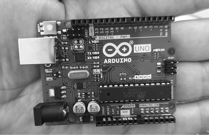
Figure 2-1: An Arduino Uno is quite small.
Although it might not look like much to the uninitiated, the Arduino system allows you to create devices that can interact with the world around you. With an almost unlimited range of input and output devices, such as sensors, indicators, displays, motors, and more, you can program the exact interactions you need to create a functional device. For example, artists have created installations with patterns of blinking lights that respond to the movements of passers-by, high school students have built autonomous robots that can detect an open flame and extinguish it, and geographers have designed systems that monitor temperature and humidity and transmit this data back to their offices via text message. In fact, a quick internet search will turn up an almost infinite number of examples of Arduino-based devices.
Let’s explore our Arduino Uno hardware (in other words, the “physical part”) in more detail and see what we have. Don’t worry too much about understanding what you see here, because all these things will be discussed in greater detail in later chapters.
Starting at the left side of the board, you’ll see two connectors, as shown in Figure 2-2.
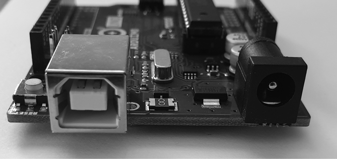
Figure 2-2: The USB and power connectors
On the left is the Universal Serial Bus (USB) connector. This connects the board to your computer, for three reasons: to supply power to the board, to upload your instructions to the Arduino, and to send data to and receive it from a computer. On the right is the power connector. Through this connector, you can power the Arduino with a standard wall power adapter (stepped down to 5 volts, of course).
At the lower middle is the heart of the board: the microcontroller, as shown in Figure 2-3.

Figure 2-3: The microcontroller
The microcontroller is the “brains” of the Arduino. It is a tiny computer that contains a processor to execute instructions, includes various types of memory to hold data and instructions from our sketches, and provides various avenues for sending and receiving data. Just below the microcontroller are two groups of small sockets, as shown in Figure 2-4.

Figure 2-4: The power and analog sockets
The group on the left offers power connections and the ability to use an external RESET button. The group on the right offers six analog inputs that are used to measure electrical signals that vary in voltage. Furthermore, pins A4 and A5 can also be used for sending data to and receiving it from other devices.
Along the top of the board are two more groups of sockets, as shown in Figure 2-5.

Figure 2-5: The digital input/output pins
The sockets (or pins) numbered 0 to 13 are digital input/output (I/O) pins. They can either detect whether or not an electrical signal is present or generate a signal on command. Pins 0 and 1 are also known as the serial port, which is used to exchange data with other devices, such as a computer via the USB connector circuitry. The pins labeled with a tilde (~) can also generate a varying electrical signal (which looks like an ocean wave on an oscilloscope—thus the wavy tilde). This can be useful for such things as creating lighting effects or controlling electric motors.
The Arduino has some very useful devices called light-emitting diodes (LEDs); these very tiny devices light up when a current passes through them. The Arduino board has four LEDs: one on the far right labeled ON, which indicates when the board has power, and three in another group, as shown in Figure 2-6.
The LEDs labeled TX and RX light up when data is being transmitted or received, respectively, between the Arduino and attached devices via the serial port and USB. The L LED is for your own use (it is connected to the digital I/O pin number 13). The little black square to the left of the LEDs is a tiny microcontroller that controls the USB interface that allows your Arduino to send data to and receive it from a computer, but you don’t generally have to concern yourself with it.
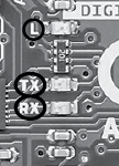
Figure 2-6: The onboard LEDs

Figure 2-7: The RESET button
Finally, the RESET button is shown in Figure 2-7.
As with a normal computer, sometimes things can go wrong with the Arduino. When all else fails, you might need to reset the system and restart your Arduino. The simple RESET button on the board is used to restart the system to resolve these problems.
One of the great advantages of the Arduino system is its ease of expandability—that is, it’s easy to add more hardware functions. The two rows of sockets along each side of the Arduino allow the connection of a shield, another circuit board with pins that allow it to plug into the Arduino. For example, the shield shown in Figure 2-8 contains an Ethernet interface that allows the Arduino to communicate over networks and the internet.

Figure 2-8: Arduino Ethernet interface shield
Notice that the Ethernet shield also has rows of sockets. These enable you to insert one or more shields on top. For example, Figure 2-9 shows that another shield with a large numeric display, a temperature sensor, extra data storage space, and a large LED has been inserted.
If you use Arduino shields in your devices, you will need to remember which shield uses which individual inputs and outputs to ensure that “clashes” do not occur. You can also purchase completely blank shields that allow you to add your own circuitry. This will be explained further in Chapter 7.
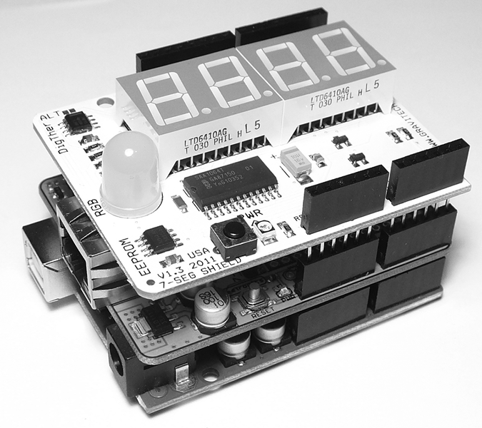
Figure 2-9: Numeric display and temperature shield
The companion to the Arduino hardware is the software, a collection of instructions that tell the hardware what to do and how to do it.
Back in Chapter 1, you installed the IDE software on your personal computer and configured it for your Arduino. Now you’re going to look more closely at the IDE and then write a simple program—known as a sketch—for the Arduino.
Taking a Look Around the IDE
As shown in Figure 2-10, the Arduino IDE resembles a simple word processor. The IDE is divided into three main areas: the command area, the text area, and the message window area.
The Command Area
The command area, shown at the top of Figure 2-10, includes the title bar, menu items, and icons. The title bar displays the sketch’s filename (such as Blink), as well as the version of the IDE (such as Arduino 2.0.0-beta.4). Below this is a series of menu items (File, Edit, Sketch, Tools, and Help) and icons, as described next.
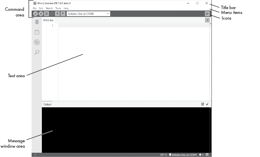
Figure 2-10: The Arduino IDE
Menu Items
As with any word processor or text editor, you can click one of the menu items to display its various options:
- File Contains options to save, load, and print sketches; a thorough set of example sketches to open; and the Preferences submenu
- Edit Contains the usual copy, paste, and search functions common to any word processor
- Sketch Contains a function to verify your sketch before uploading it to a board, as well as some sketch folder and import options
- Tools Contains a variety of functions as well as the commands to select the Arduino board type and USB port
- Help Contains links to various topics of interest and the version of the IDE
The Icons
Below the menu toolbar are six icons. Mouse over each icon to display its name. The icons, from left to right, are as follows:
- Verify Click this to check that the Arduino sketch is valid and doesn’t contain any programming mistakes.
- Upload Click this to verify and then upload your sketch to the Arduino board.
- New Click this to open a new blank sketch in a new window.
- Debug Used with more complex Arduino boards for real-time debugging.
- Open Click this to open a saved sketch.
- Save Click this to save the open sketch. If the sketch doesn’t have a name, you will be prompted to create one.
- Serial Monitor Click this to open a new window for use in sending and receiving data between your Arduino and the IDE.
The Text Area
The text area is shown in the middle of Figure 2-10. This is where you’ll create your sketches. The name of the current sketch is displayed in the tab at the upper left of the text area. (The default name is the current date.) You’ll enter the contents of your sketch here as you would in any text editor.
The Output Window
The output window is shown at the bottom of Figure 2-10. Messages from the IDE appear in the black area. The messages you see will vary and will include messages about verifying sketches, status updates, and so on.
At the bottom right of the output window, you should see the name of your Arduino board type as well as its connected USB port—Arduino/Genuino Uno on COM4 in this case.
Creating Your First Sketch in the IDE
An Arduino sketch is a set of instructions that you create to accomplish a particular task; in other words, a sketch is a program. In this section, you’ll create and upload a simple sketch that will cause the Arduino’s LED (shown in Figure 2-11) to blink repeatedly, by turning it on and then off at one second intervals.
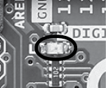
Figure 2-11: The LED on the Arduino board, next to the capital L
To begin, connect your Arduino to your computer with the USB cable. Then open the IDE and select your board (Arduino Uno) and USB port type from the drop-down menu, as shown in Figure 2-12. This ensures that the Arduino board is properly connected.
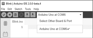
Figure 2-12: Selecting the Arduino Uno board
Comments
First, enter a comment as a reminder of what your sketch will be used for. A comment in a sketch is a note written for the user’s benefit. Comments can be notes to yourself or others, and they can include instructions or any other details. When creating sketches for your Arduino, it’s a good idea to add comments about your intentions for the code; these comments can prove useful later when you’re revisiting a sketch.
To add a comment on a single line, enter two forward slashes and then the comment, like this:
// Blink LED sketch by Mary Smith, created 07/01/2021The two forward slashes tell the IDE to ignore that line of text when verifying a sketch, or checking that everything is written properly with no errors.
To enter a comment that spans two or more lines, enter the characters /* on a line before the comment and end the comment with the characters */ on the following line, like this:
/*
Arduino Blink LED Sketch
by Mary Smith, created 07/01/2021
*/
The /* and */ tell the IDE to ignore the text that they bracket.
Enter a comment describing your Arduino sketch using one of these methods. Then save your sketch by choosing File▶Save As. Enter a short name for your sketch (such as blinky) and click OK.
The default filename extension for Arduino sketches is .ino, and the IDE should add this automatically. The name for your sketch should be, in this case, blinky.ino, and you should be able to see it in your Sketchbook.
The setup() Function
The next stage in creating any sketch is to fill in the void setup() function. This function contains a set of instructions for the Arduino to execute once only, each time it is reset or turned on. To create the setup() function, add the following lines to your sketch, after the comments:
void setup()
{
}
Controlling the Hardware
Our program will blink the user LED on the Arduino. The user LED is connected to the Arduino’s digital pin 13. A digital pin can either detect an electrical signal or generate one on command. In this project, we’ll generate an electrical signal that will light the LED.
Enter the following into your sketch between the braces ({ and }):
pinMode(13, OUTPUT); // set digital pin 13 to outputThe number 13 in the listing represents the digital pin you’re addressing. You’re setting this pin to OUTPUT, which means it will generate an electrical signal. If you wanted it to detect an incoming electrical signal, then you would set the pin’s mode to INPUT instead. Notice that the pinMode() line ends with a semicolon (;). Every instruction line in your Arduino sketches will end with a semicolon.
Save your sketch at this point to make sure that you don’t lose any of your work.
The loop() Function
Remember that our goal is to make the LED blink repeatedly. To do this, we’ll create a loop() function to tell the Arduino to execute an instruction over and over until the power is shut off or someone presses the RESET button.
Enter the code shown in boldface after the void setup() section in the following listing to create an empty loop() function. Be sure to end this new section with another brace (}), and then save your sketch again:
/*
Arduino Blink LED Sketch
by Mary Smith, created 07/01/21
*/

void setup()
{
   pinMode(13, OUTPUT); // set digital pin 13 to output
}
void loop()
{
   // place your main loop code here:
}Next, enter the actual functions into void loop() for the Arduino to execute.
Enter the following between the loop() function’s braces. Then click Verify to make sure that you’ve entered everything correctly:
digitalWrite(13, HIGH); // turn on digital pin 13
delay(1000);            // pause for one second
digitalWrite(13, LOW);  // turn off digital pin 13
delay(1000);            // pause for one second
Let’s take this apart. The digitalWrite() function controls the voltage that is output from a digital pin: in this case, pin 13, connected to the LED. By setting the second parameter of this function to HIGH, we tell the pin to output a “high” digital voltage; current will flow from the pin, and the LED will turn on.
The delay() function causes the sketch to do nothing for a period of time—in this case, with the LED turned on, delay(1000) causes it to remain lit for 1,000 milliseconds, or 1 second.
Next, we turn off the voltage to the LED with digitalWrite(13, LOW);. The current flowing through the LED stops, and the light turns off. Finally, we pause again for 1 second while the LED is off, with delay(1000);.
The completed sketch should look like this:
/*
Arduino Blink LED Sketch
by Mary Smith, created 07/01/21
*/

void setup()
{
   pinMode(13, OUTPUT); // set digital pin 13 to output
}

void loop()
{
   digitalWrite(13, HIGH); // turn on digital pin 13
   delay(1000);            // pause for one second
   digitalWrite(13, LOW);  // turn off digital pin 13
   delay(1000);            // pause for one second
}
Before you do anything further, save your sketch!
Verifying Your Sketch
When you verify your sketch, you ensure that it has been written correctly in a way that the Arduino can understand. To verify your complete sketch, click Verify in the IDE and wait a moment. Once the sketch has been verified, a note should appear in the output window, as shown in Figure 2-13.
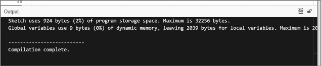
Figure 2-13: The sketch has been verified.
This “Done compiling” message tells you that the sketch is okay to upload to your Arduino. It also shows how much memory it will use (924 bytes in this case) of the total available on the Arduino (32,256 bytes).
But what if your sketch isn’t okay? Say, for example, you forgot to add a semicolon at the end of the second delay(1000) function. If something is broken in your sketch, then when you click Verify, the message window should display a verification error message similar to the one shown in Figure 2-14.
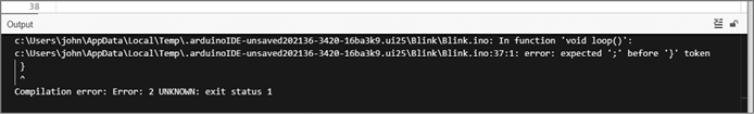
Figure 2-14: The message window with a verification error
The IDE displays the error itself (the missing semicolon, described by error: expected ';' before'}' token). It should also highlight the location of the error, or a spot just after it. This helps you easily locate and rectify the mistake.
Uploading and Running Your Sketch
Once you’re satisfied that your sketch has been entered correctly, save it. Then make sure that your Arduino board is connected to your computer and click Upload in the IDE. The IDE verifies your sketch again and then uploads it to your Arduino board. During this process, the TX/RX LEDs on your board (shown in Figure 2-6) should blink, indicating that information is traveling between the Arduino and your computer.
Now for the moment of truth: your Arduino should start running the sketch. If you’ve done everything correctly, the LED should blink on and off once every second!
Congratulations. You now know the basics of how to enter, verify, and upload an Arduino sketch.
Modifying Your Sketch
After running your sketch, you may want to change how it operates by, for example, adjusting the on or off delay time for the LED. Because the IDE is a lot like a word processor, you can open your saved sketch, adjust the values, and then save your sketch again and upload it to the Arduino. For example, to increase the rate of blinking, change both delay functions to make the LEDs blink for one-quarter of a second by adjusting the delay to 250, like this:
delay(250); // pause for one-quarter of one secondThen upload the sketch again. The LED should now blink faster, for one-quarter of a second each time.
Looking Ahead
Armed with your newfound knowledge of how to enter, edit, save, and upload Arduino sketches, you’re ready for the next chapter, where you’ll learn how to use more functions, implement good project design, construct basic electronic circuits, and do much more.