
Chapter 4
Creating and Modifying Drawing Objects
All drawings start off as an idea. Maybe it's just in your head, or maybe it became a sketch done on a napkin over lunch. The idea or sketch is then handed over to a drafter or engineer, who creates a set of drawings that will be used to communicate the final design. The final design is then used to manufacture the parts or construct the building. A drafter or engineer completes a design using a variety of objects, from lines to circles, and even splines and hatch patterns.
Although adding objects to a drawing is how most designs start off, those objects are often used to create new objects or are modified to refine a design. Most users of the AutoCAD® program, on average, spend more time modifying objects than creating new objects. When automating tasks with VBA, be sure to look at tasks related not only to creating objects but also to modifying objects.
In this chapter, you will learn to create 2D graphical objects and how to work with nongraphical objects, such as layers and linetypes. Along with creating objects, you will learn how to modify objects.
Due to limitations on the number of pages available for this book, additional content that covers working with 2D and 3D objects is presented in the bonus chapters available on the companion website. The companion website is located here: www.sybex.com/go/autocadcustomization.
Understanding the Basics of a Drawing-Based Object
Each drawing contains two different types of objects: nongraphical and graphical. Nongraphical objects represent the layers, block definitions, named styles, and other objects that are stored in a drawing but aren't present in model space or on a named layout. Nongraphical objects can, and typically do, affect the display of graphical objects.
Although model space and named layouts are typically not thought of as nongraphical objects, they are. Model space is a special block definition, whereas a layout is an object that is based on a plot configuration—commonly called a page setup—with a reference to a block definition. Graphical objects are those objects that are added to model space or a named layout, such as lines, circles, and text. Every graphical object added to a drawing references at least one nongraphical object and is owned by one nongraphical object. The nongraphical object that each graphical object references is a layer, and each graphical object is owned by model space or a named layout.
In the AutoCAD Object library, any object that can be added to a drawing is derived from or based on the AcadObject object type. For example, an AcadLine object that represents a line segment and an AcadLayer object that represents a layer have the same properties and methods as the AcadObject object type. You can think of the AcadObject as a more general or generic object in the terms of AutoCAD objects, much like you might use the term automobile to describe a vehicle with four wheels. Figure 4.1 shows the object hierarchy of nongraphical and graphical objects.
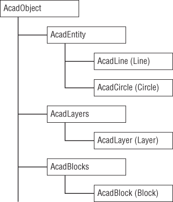
Figure 4.1 Drawing object hierarchy
Table 4.1 lists the properties of the AcadObject object that you use to get information about an object in a drawing.
Table 4.1 Properties related to the AcadObject object
| Property | Description |
Application |
Returns the AcadApplication object that represents the current AutoCAD session. I discussed working with the AcadApplication object in Chapter 3, “Interacting with the Application and Documents Objects.” |
Document |
Returns the AcadDocument object that represents the drawing in which the object is stored. I discussed working with the AcadDocument object in Chapter 3. |
Handle |
Returns a string that represents a unique hexadecimal value that differentiates one object from another in a drawing; think of it along the lines of a database index. An object's handle persists between drawing sessions. A handle, while unique to a drawing, can be assigned to another object in a different drawing. |
HasExtensionDictionary |
Returns True if an extension dictionary has been attached to the object. I discuss extension dictionaries in Chapter 9, “Storing and Retrieving Custom Data.” |
ObjectID |
Returns a unique integer that differentiates one object from another in a drawing; think of it along the lines of a database index. Unlike a handle, the object ID of an object might be different each time a drawing is loaded into memory. |
ObjectID32 |
Same as the ObjectID property, but must be used on 64-bit releases of Windows. This property is only valid with AutoCAD 2009 through 2014. Use the ObjectID property for earlier releases and AutoCAD 2015. |
ObjectName |
Returns a string that represents the object's internal classname. This value can be used to distinguish one object type from another as part of a conditional statement. |
OwnerID |
Returns the object ID of the object's parent. For example, the parent of a line might be model space or a named layout whereas the text style symbol table is the parent of a text style. |
OwnerID32 |
Same as the OwnerID property, but must be used on 64-bit releases of Windows. This property is only valid with AutoCAD 2009 through 2014. Use the OwnerID property for earlier releases and AutoCAD 2015. |
In addition to the properties that are shared across all drawing-based objects, several methods are shared. The Delete method is used to remove an object from a drawing; it is the AutoCAD Object library equivalent of the erase command. The other three shared methods are used to work with extension dictionaries and extended data (Xdata). These three methods are GetExtensionDictionary, GetXData, and SetXData, and I cover them in Chapter 9.
All graphical objects in a drawing are represented by the AcadEntity object. The AcadEntity object inherits the properties and methods of the AcadObject object and adds additional properties and methods that all graphical objects have in common. For example, all graphical objects can be assigned a layer and moved in the drawing. The Layer property of the AcadEntity object is used to specify the layer in which an object is placed, and the Move method is used to relocate an object in the drawing. Objects based on the AcadEntity object can be added to model space, a named layout, or a block definition.
Table 4.2 lists the properties of the AcadEntity object that you can use to get information about and control the appearance of a graphical object in a drawing.
Table 4.2 Properties related to the AcadEntity object
| Property | Description |
EntityTransparency |
Specifies the transparency for an object. See Bonus Chapter 1, “Working with 2D Objects and Object Properties.” |
Hyperlinks |
Returns the AcadHyperlinks collection object assigned to an object. See Bonus Chapter 1. |
Layer |
Specifies the layer for an object. See Bonus Chapter 1. |
Linetype |
Specifies the linetype for an object. See Bonus Chapter 1. |
LinetypeScale |
Specifies the linetype scale for an object. See Bonus Chapter 1. |
Lineweight |
Specifies the lineweight for an object. See Bonus Chapter 1. |
Material |
Specifies the name of the material to use when an object is rendered. See Bonus Chapter 2, “Modeling in 3D Space.” |
PlotStyleName |
Specifies the name of the plot style for an object. See Bonus Chapter 1. |
TrueColor |
Specifies the color assigned to an object. See Bonus Chapter 1. |
Visible |
Specifies the visibility for an object. See Bonus Chapter 1. |
Table 4.3 lists the methods that all graphical objects inherit from the AcadEntity object.
Table 4.3 Methods related to the AcadEntity object
| Method | Description |
ArrayPolar |
Creates a polar array from an object. See Bonus Chapter 1. |
ArrayRectangular |
Creates a rectangular array from an object. See Bonus Chapter 1. |
Copy |
Duplicates an object. See the “Copying and Moving Objects” section. |
GetBoundingBox |
Returns an array of doubles that represents the lower and upper points of an object's extents. See Bonus Chapter 1. |
Highlight |
Highlights or unhighlights an object. See Bonus Chapter 1. |
IntersectWith |
Returns an array of doubles that represents the intersection points between two objects. See Bonus Chapter 1. |
Mirror |
Mirrors an object along a vector. See Bonus Chapter 1. |
Mirror3D |
Mirrors an object about a plane. See Bonus Chapter 2. |
Move |
Moves an object. See the “Copying and Moving Objects” section. |
Rotate |
Rotates an object around a base point. See the “Rotating Objects” section. |
Rotate3D |
Rotates an object around a vector. See Bonus Chapter 2. |
ScaleEntity |
Uniformly increases or decreases the size of an object. See Bonus Chapter 1. |
TransformBy |
Applies a transformation matrix to an object. A transformation matrix can be used to scale, rotate, move, and mirror an object in a single operation. See Bonus Chapter 1. |
Update |
Instructs AutoCAD to recalculate the display of an object; similar to the regen command but it only affects the object in which the method is executed. See the “Modifying Objects” section. |
Accessing Objects in a Drawing
Before working with nongraphical and graphical objects, you must understand where objects are located in the AutoCAD Object hierarchy. Nongraphical objects are stored in collection objects that are accessed from an AcadDocument or ThisDrawing object. Even graphical objects displayed in model space, on named layouts, or in a block definition require you to work with a collection object. I explained how to work with the AcadDocument object in Chapter 3.
To access the collection objects of a drawing, use the properties of an AcadDocument object. Collection objects may also be referred to as symbol tables or dictionaries the AutoLISP and Managed .NET programming languages (Table 4.4).
Table 4.4 Properties used to access the collection objects of an AcadDocument object
| Property | Description |
Blocks |
Returns an AcadBlocks collection object that contains the block definitions stored in a drawing, even model space, paper space, and those used for named layouts. See Chapter 7, “Working with Blocks and External References,” for more information. |
Dictionaries |
Returns an AcadDictionaries collection object that contains the named dictionaries stored in a drawing. See Chapter 9 for more information. |
DimStyles |
Returns an AcadDimStyles collection object that contains the dimension styles stored in a drawing. See Chapter 6, “Annotating Objects,” for more information. |
FileDependencies |
Returns an Acad FileDependencies collection object that contains the external file dependencies used by a drawing. See Chapter 7 for more information. |
Groups |
Returns an AcadGroups collection object that contains the named groups defined in a drawing. See Bonus Chapter 1. |
Layers |
Returns an AcadLayers collection object that contains the layers stored in a drawing. See Bonus Chapter 1. |
Layouts |
Returns an AcadLayouts collection object that contains the named layouts stored in a drawing. See Chapter 8, “Outputting Drawings,” for more information. |
Linetypes |
Returns an AcadLinetypes collection object that contains the linetypes stored in a drawing. See Bonus Chapter 1. |
Materials |
Returns an AcadMaterialss collection object that contains the names of the materials stored in a drawing. See Bonus Chapter 2. |
ModelSpace |
Returns an AcadBlock object that is a reference to model space in the drawing. See the “Working with Model or Paper Space” section. |
PaperSpace |
Returns an AcadBlock object that is a reference to paper space in the drawing. See the “Working with Model or Paper Space” section. |
PlotConfigurations |
Returns an Acad PlotConfigurations collection object that contains the named plot configurations stored in a drawing. See Chapter 8 for more information. |
RegisteredApplications |
Returns an AcadRegisteredApplications collection object that contains the names of all registered applications that store custom data in a drawing. See Chapter 9 for more information. |
TextStyles |
Returns an AcadTextStyles collection object that contains the text styles stored in a drawing. See Chapter 6 for more information. |
UserCoordinateSystems |
Returns an AcadUCSs collection object that contains the user coordinate systems saved in a drawing. See Bonus Chapter 2. |
Viewports |
Returns an AcadViewports collection object that contains the named arrangements of tiled viewports for use in model space. See Chapter 5, “Interacting with the User and Controlling the Current View,” for more information. |
Working with Model or Paper Space
Graphical objects created by the end user or with the AutoCAD Object library are all added to a block definition. Although this might seem a bit confusing at first, model space is nothing more than a block definition that is edited using the drawing area displayed in the drawing window. The same is true with paper space and the named layouts stored in a drawing. Before you can add or modify an object in a drawing file, you must determine which block definition to work with.
Model space and paper space are accessed using the ModelSpace and PaperSpace properties of an AcadDocument or ThisDrawing object. You use the ModelSpace property to get a reference to an AcadModelSpace object, which is actually a reference to the block definition named *MODEL_SPACE. The PaperSpace property returns a reference to an AcadPaperSpace object, which is a reference to the most recently accessed paper space block. The initial paper space block is named *PAPER_SPACE or *PAPER_SPACE0. Switching named layouts changes which paper space block is returned by the PaperSpace property.
You use the AcadModelSpace and AcadPaperSpace objects to access the graphical objects in a drawing. A majority of the methods that these two objects support are related to adding new graphical objects. To add new graphical objects to a drawing, use the methods whose names start with the prefix Add. I explain how to add graphical objects to model space in the next section and I cover how to access the objects already in model space in the “Getting an Object in the Drawing” section. You can learn more about the properties and methods specific to block definitions in Chapter 7 and the properties and methods specific to named layouts in Chapter 8.
The standard commands of AutoCAD typically work in the current context of the drawing. If model space is active and the line command is started, the line object is added to model space. However, if the line command is started when a named layout is current, the line is added to the named layout. The AutoCAD Object library isn't concerned with the active space. Model space might be active, but objects can be added to paper space and vice versa. The active space can be bypassed with the AutoCAD Object library and VBA because you have direct access to the objects in a drawing's database.
The active space doesn't matter so much when adding and modifying objects with the AutoCAD Object library, but users still expect macros to be executed in the current context of the drawing. The ActiveSpace property can be used to determine which space is active. A constant value of acModelSpace or acPaperSpace is returned by the ActiveSpace property; acModelSpace is returned when model space is current. You can also use the ActiveSpace property to switch the active space; assign the constant value of acPaperSpace to switch to paper space when model space is current.
The following code statements display a message containing the number of objects in the current space:
Dim nCnt As Integer
nCnt = 0
Select Case ThisDrawing.ActiveSpace
  Case acModelSpace
    nCnt = ThisDrawing.ModelSpace.Count
  Case acPaperSpace
    nCnt = ThisDrawing.PaperSpace.Count
End Select
MsgBox "Number of objects in current space: " & CStr(nCnt)Creating Graphical Objects
Graphical objects are used to communicate a design, whether a mechanical fastener or a new football stadium. AutoCAD supports two types of graphical objects: straight and curved. Straight objects, such as lines, rays, and xlines, contain only straight segments. Curved objects can have curved segments, but as an option can have straight segments, too. Arcs, circles, splines, and polylines with arcs are considered examples of curved objects. I cover commonly used straight and curved objects in the “Adding Straight Line Segments” and “Working with Curved Objects” sections. Polylines are discussed in the “Working with Polylines” section.
Adding Straight Line Segments
Straight objects are used in a variety of drawings created by drafters and engineers. You can use a straight object to represent the following:
- The top of a bolt head
- The tooth of a gear
- A wire in a wiring diagram
- The edge of a student desk
- The face of a wall for a building
Lines are straight objects with a defined start point and endpoint and are represented by the AcadLine object. The AddLine function allows you to create a line object drawn between two points. The following shows the syntax of the AddLine function:
retVal = object.AddLine(startPoint, endPoint)Its arguments are as follows:
retValTheretValargument represents the newAcadLineobject returned by theAddLinefunction.objectTheobjectargument represents theAcadModelSpacecollection object.startPointThestartPointargument is an array of three doubles that defines the start point of the new line.endPointThe endPoint argument is an array of three doubles that defines the endpoint of the new line.
The following code statements add a new line object to model space (see Figure 4.2):
' Defines the start and endpoint for the line
Dim dStartPt(2) As Double, dEndPt(2) As Double
dStartPt(0) = 0: dStartPt(1) = 0: dStartPt(2) = 0
dEndPt(0) = 5: dEndPt(1) = 5: dEndPt(2) = 0
Dim oLine As AcadLine
Set oLine = ThisDrawing.ModelSpace.AddLine(dStartPt, dEndPt)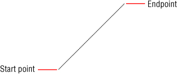
Figure 4.2 Definition of a line
Using the AcadLine object returned by the AddLine function, you can obtain information about and modify the line's properties. In addition to the properties that the AcadLine object shares in common with the AcadEntity object, you can use the properties listed in Table 4.5 when working with an AcadLine object.
Table 4.5 Properties related to an AcadLine object
| Property | Description |
Angle |
Returns a double that represents the angle of the line expressed in radians. All angles are stored in a drawing file as radians. |
Delta |
Returns an array of three double values that represent the delta of the line: the difference between the line's start and endpoints. |
EndPoint |
Specifies the endpoint of the line. |
Length |
Returns a double that represents the length of the line. |
Normal |
Specifies the normal vector of the line. The normal vector is an array of three double values, which defines the positive Z-axis of the line. |
StartPoint |
Specifies the start point of the line. |
Thickness |
Specifies the thickness assigned to the line; the value must be numeric. The default is 0; anything greater than 0 results in the creation of a 3D planar object. |
Working with Curved Objects
Straight objects are used in many designs, but they aren't the only objects. Curved objects are used to soften the edges of a design and give a design a more organic look. You can use a curved object to represent any of the following:
- A hole in a plate
- A fillet on a metal bracket
- A round edge on the top of a desk
- A cross section of a shaft or hub
I discuss how to create and modify circles in the upcoming sections.
Creating and Modifying Circles
Circles are one of the most commonly used curved objects in mechanical designs, but they are less frequently used in architectural and civil designs. Drill holes in the top view of a model, the center of a gear, or the grommet in the side of a desk are typically circular and are drawn using circles. Circles in a drawing are represented by the AcadCircle object in the AutoCAD Object library. The AddCircle function allows you to create a circle object based on a center point and radius value, and the function returns an AcadCircle object that represents the new circle. The following shows the syntax of the AddCircle function:
retVal = object.AddCircle(centerPoint, radius)Its arguments are as follows:
retValTheretValargument represents the newAcadCircleobject returned by theAddCirclefunction.objectTheobjectargument represents theAcadModelSpacecollection object.centerPointThecenterPointargument is an array of three doubles that defines the center point of the new circle.radiusTheradiusargument is a double that specifies the radius of the new circle. If you know the diameter of the circle you want to create, divide that value in half to get the radius for the circle.
The following code statements add a new circle object to model space (see Figure 4.3):
' Defines the center point for the circle object
Dim dCenPt(2) As Double
dCenPt(0) = 2.5: dCenPt(1) = 1: dCenPt(2) = 0
' Adds the circle object to model space with a radius of 4
Dim oCirc As AcadCircle
Set oCirc = ThisDrawing.ModelSpace.AddCircle(dCenPt, 4)
Figure 4.3 Definition of a circle
The properties and methods of the AcadCircle object returned by the AddCircle function can be used to obtain information about and modify the circle. An AcadCircle object shares properties and methods in common with the AcadEntity object, but it has additional properties that describe the circle object. Table 4.6 lists the properties specific to the AcadCircle object.
Table 4.6 Properties related to an AcadCircle object
| Property | Description |
Area |
Returns a double that represents the calculated area of the circle. |
Center |
Specifies the center point of the circle. That value is expressed as an array of three doubles. |
Circumference |
Returns a double that represents the circumference of the circle. |
Diameter |
Specifies the diameter of the circle; the value is a double. |
Normal |
Specifies the normal vector of the line. The normal vector is an array of three doubles that defines the positive Z-axis for the circle. |
Radius |
Specifies the radius of the circle; the value is a double. |
Thickness |
Specifies the thickness assigned to the circle; the value must be numeric. The default is 0; anything greater than 0 results in the creation of a 3D cylinder object. |
Adding and Modifying Arcs
Fillets and rounded corners are common in many types of designs, and they are drawn using arcs. Arcs are partial circles represented by the AcadArc object. An arc is added to a drawing with the AddArc function. Unlike drawing arcs with the arc command, which offers nine options, the AddArc function offers only one approach to adding an arc, and that is based on a center point, two angles (start and end), and a radius. The AddArc function returns an AcadArc object that represents the new arc added to the drawing. The following shows the syntax of the AddArc function:
retVal = object.AddArc(centerPoint, radius, startAngle, endAngle)Its arguments are as follows:
retValTheretValargument represents the newAcadArcobject returned by theAddArcfunction.objectTheobjectargument represents theAcadModelSpacecollection object.centerPointThecenterPointargument is an array of three doubles that defines the center point of the new arc.radiusTheradiusargument is a double that specifies the radius of the new arc.startAngleandendAngleThestartAngleandendAnglearguments are doubles that specify the starting and end angle of the new arc, respectively. A start angle larger than the end angle results in the arc being drawn in a counterclockwise direction. Angles are measured in radians.
The following code statements add a new arc object to model space (see Figure 4.4):
' Defines the center point for the arc object
Dim dCenPt(2) As Double
dCenPt(0) = 2.5: dCenPt(1) = 1: dCenPt(2) = 0
' Sets the value of PI
Dim PI As Double
PI = 3.14159265
' Adds the arc object to model space with a radius of 4
Dim oArc As AcadArc
Set oArc = ThisDrawing.ModelSpace.AddArc(dCenPt, 4, PI, 0)
Figure 4.4 Definition of an arc
The AcadArc object returned by the AddArc function can be used to obtain information about and modify the object's properties and methods. In addition to the properties that the AcadArc object shares in common with the AcadEntity object, you can use the properties listed in Table 4.7 when working with an AcadArc object.
Table 4.7 Properties related to an AcadArc object
| Property | Description |
ArcLength |
Returns a double that represents the length along the arc. |
Area |
Returns a double that represents the calculated area of the arc. |
Center |
Specifies the center point of the arc. The value is expressed as an array of three doubles. |
EndAngle |
Specifies a double that represents the end angle of the arc. |
EndPoint |
Returns an array of doubles that represents the endpoint of the arc. |
Normal |
Specifies the normal vector of the line. The normal vector is an array of three doubles that defines the positive Z-axis for the arc. |
Radius |
Specifies the radius of the arc; the value is a double. |
StartAngle |
Specifies a double that represents the start angle of the arc. |
StartPoint |
Returns an array of doubles that represents the start point of the arc. |
Thickness |
Specifies the thickness assigned to the circle; the value must be numeric. The default is 0; anything greater than 0 results in the creation of a curved 3D object. |
TotalAngle |
Returns a double that represents the angle of the arc: the end angle minus the start angle. |
Working with Polylines
Polylines are objects that can be made up of multiple straight and/or curved segments. Although lines and arcs drawn end to end can look like a polyline, polylines are more efficient to work with. Because a polyline is a single object made up of multiple segments, it is easier to modify. For example, all segments of a polyline are offset together instead of individually. If you were to offset lines and arcs that were drawn end to end, the resulting objects wouldn't be drawn end to end like the original objects (see Figure 4.5).

Figure 4.5 Offset polylines and lines
There are two types of polylines that you can create and modify:
- Polyline Legacy polylines were available in AutoCAD R13 and earlier releases, and they are still available in AutoCAD R14 and later releases. This type of polyline object supports 3D coordinate values, but it uses more memory and increase the size of a drawing file.
- Lightweight Polyline Lightweight polylines, or LWPolylines, were first introduced in AutoCAD R14. They are more efficient in memory and require less space in a drawing file. Lightweight polylines support only 2D coordinate values.
Legacy polylines are represented by the AcadPolyline object type and can be added to a drawing with the AddPolyline function. LWPolylines are represented by the AcadLWPolyline object type and can be added to a drawing with the AddLightWeightPolyline function. The AddPolyline and AddLightWeightPolyline functions both require you to specify a list of vertices.
A vertices list is defined using an array of doubles. The number of elements in the array varies by the type of polyline you want to create or modify. To create an AcadPolyline object, you define an array of doubles in multiples of three, whereas an array of doubles must be in multiples of two to create an AcadLWPolyline object. For example, an AcadPolyline object with three vertices would require an array with nine elements (three elements × three vertices). For an LWPolyline, each vertex requires two elements in an array, so an AcadLWPolyline object with three vertices would require a vertices list with six elements (two elements × three vertices).
The following shows an example of a six-element array that defines three 2D points representing the corners of a triangle:
' Defines a six element array of doubles
Dim dVecList(5) As Double
' Sets the first corner
dVecList(0) = 0#: dVecList(1) = 0#
' Sets the second corner
dVecList(2) = 3#: dVecList(3) = 0#
' Sets the third corner
dVecList(4) = 1.5: dVecList(5) = 2.5981
The following shows the syntax of the AddLightWeightPolyline and AddPolyline functions:
retVal = object.AddLightWeightPolyline(vecList)
retVal = object.AddPolyline(vecList)
The arguments are as follows:
retValTheretValargument represents the newAcadLWPolylineorAcadPolylineobject returned by theAddLightWeightPolylineorAddPolylinefunction.ObjectTheobjectargument represents theAcadModelSpacecollection object.vecListThevecListargument is an array of doubles that defines the vectors of the polyline. For theAddLightWeightPolylinefunction, the array must contain an even number of elements since each vertex is defined by two elements. Specify an array in three-element increments when using theAddPolylinefunction since each vertex is defined by three elements.
The following code statements add a new lightweight polyline object to model space (see Figure 4.6):
' Adds a lightweight polyline
Dim oLWPoly As AcadLWPolyline
Set oLWPoly = ThisDrawing.ModelSpace.AddLightWeightPolyline(dVecList)
Figure 4.6 Polyline with three vertices
Using the AcadLWPolyline or AcadPolyline object returned by the AddLightWeightPolyline or AddPolyline function, you can obtain information about and modify the polyline's properties. In addition to the properties that the AcadLWPolyline or AcadPolyline object share in common with the AcadEntity object, you can use the properties listed in Table 4.8 when working with an AcadLWPolyline or AcadPolyline object.
Table 4.8 Properties related to an AcadLWPolyline or AcadPolyline object
| Property | Description |
Area |
Returns a double that represents the calculated area of the polyline. |
Closed |
Specifies whether the polyline is open or closed. A value of True closes the polyline if the object contains more than two vertices. |
ConstantWidth |
Specifies the global width for all segments of the polyline. |
Coordinate |
Specifies the coordinate value of a specific vertex in the polyline. |
Coordinates |
Specifies the coordinate values for all vertices of the polyline. |
Elevation |
Specifies the elevation at which the polyline is drawn. |
Length |
Returns a double that represents the length of the polyline. |
LinetypeGeneration |
Specifies whether the linetype pattern assigned to the polyline is generated across the polyline as one continuous pattern, or whether the pattern begins and ends at each vertex. A value of True indicates that the linetype pattern should be generated across the polyline as one continuous pattern. |
Normal |
Specifies the normal vector of the polyline. The normal vector is an array of three doubles that defines the positive Z-axis for the polyline. |
Thickness |
Specifies the thickness assigned to the polyline; the value must be numeric. The default is 0; anything greater than 0 results in the creation of a 3D planar object. |
In addition to the properties listed in Table 4.8, an AcadLWPolyline or AcadPolyline object contains methods that are specific to polylines. Table 4.9 lists the methods that are unique to polylines.
Table 4.9 Methods related to an AcadLWPolyline or AcadPolyline object
| Method | Description |
AddVertex |
Adds a new 2D point at the specified vertex in the LWPolyline (supported by AcadLWPolyline objects only). |
AppendVertex |
Appends a new 3D point to the polyline (supported by AcadPolyline objects only). |
Explode |
Explodes the polyline and returns an array of the objects added to the drawing as a result of exploding the polyline. |
GetBulge |
Gets the bulge–curve–value at the specified vertex. The bulge is a value of the double data type. |
GetWidth |
Gets the width of the segment at the specified vertex. The width is a value of the double data type. |
SetBulge |
Sets the bulge–curve–value at the specified vertex. |
SetWidth |
Sets the width of the segment at the specified vertex. |
Getting an Object in the Drawing
Modifying an object after it has been added to a drawing is fairly straightforward; you use the properties and methods of the object that is returned by one of the Add* functions described in the previous sections. If you want to modify an existing object in a drawing, you must locate it in the AcadModelSpace or AcadPaperSpace collection object or a block definition represented by an AcadBlock object. I explain how to work with block definitions in Chapter 7 and with paper space in Chapter 8.
The Item method and a For statement are the most common ways to access an object in the AcadModelSpace collection object. I explained how to use the Item method and For statement in Chapter 2, “Understanding Visual Basic for Applications.” Use the Item method when you want to access a specific object in model space based on its index value; the first object in model space has an index of 0. Here are example code statements that get the handle and object type name of the first object in model space:
Dim oEnt As AcadEntity
Set oEnt = ThisDrawing.ModelSpace(0)
MsgBox "Handle: " & oEnt.Handle & vbLf & _
       "ObjectID: " & CStr(oEnt.ObjectID) & vbLf & _
       "Object Name: " & oEnt.ObjectName
The values displayed in the message box by the example code will vary from drawing to drawing. Figure 4.7 shows an example of a message box with the values from a first object in model space; the values reflected are of a point object.

Figure 4.7 Message box containing the handle and object ID of an object
A For statement is the most efficient way to step through all the objects in model space or any other collection object you might need to work with. The following code statements step through model space and return the center point and radius of each circle object:
Dim oEnt As AcadEntity
Dim oCircle As AcadCircle
' Displays a general message
ThisDrawing.Utility.Prompt vbLf & "Circles in model space"
' Steps through model space
For Each oEnt In ThisDrawing.ModelSpace
  ' Checks to see if the object is a circle
  If TypeOf oEnt Is AcadCircle Then
    Set oCircle = oEnt
    ' outputs the center point and radius of the circle
    ThisDrawing.Utility.Prompt vbLf & "Center point: " & _
                               CStr(oCircle.Center(0)) & "," & _
                               CStr(oCircle.Center(1)) & "," & _
                               CStr(oCircle.Center(2)) & _
                               vbLf & "Radius: " & _
                               CStr(oCircle.Radius)
  End If
Next oEnt
ThisDrawing.Utility.Prompt vbLf
Here is an example of the output created by the previous code statements:
Circles in model space
Center point: 5,2,0
Radius: 2.5
Center point: 6,2.5,0
Radius: 0.125
Center point: 3,1,0
Radius: 5Modifying Objects
Adding new objects is critical to completing a design, but more time is often spent by a drafter or engineer modifying existing objects than adding new objects. The AutoCAD Object library contains methods that are similar to many of the standard AutoCAD commands used to modify objects. The modifying methods of the AutoCAD Object library can be used to erase, move, scale, mirror, and rotate objects, among other tasks. I explain how to erase, copy, move, and rotate graphical objects in the following sections using the methods that are inherited by the AcadEntity object. I discuss how to scale, mirror, offset, array, and control the visibility of objects in Bonus Chapter 1 on the companion website at www.sybex.com/go/autocadcustomization.
When a change is made to an object, I recommend that you update the display of that object. The AutoCAD command regen is used to regenerate the display of all objects in the current space, but with the AutoCAD Object library you can update the display of a single graphical object or all objects in a drawing. Use the Update method to update the display of a single graphical object. The Update method doesn't accept any argument values.
If you want to update the display of all objects in a drawing, use the Regen method of the AcadDocument or ThisDrawing object. The Regen method expects a constant value from the AcRegenType enumerator. You use the acActiveViewport constant to regenerate the objects in the current viewport or the acAllViewports constant to regenerate all objects in a drawing.
The following code statements show how to update the display of the first object in model space and all objects in the current viewport:
' Update the first object in model space
ThisDrawing.ModelSpace(0).Update
' Update all objects in the current viewport
Thisdrawing.Regen acActiveViewport
Deleting Objects
All graphical and most nongraphical objects can be removed from a drawing when they are no longer needed. The only objects that can't be removed are any nongraphical objects that are referenced by a graphical object, such as a text or dimension style, and nongraphical objects that represent symbol tables, such as the Layers and Blocks symbol tables. The Delete method is used to remove—or erase—an object. The method doesn't accept any arguments. If an object can't be removed, an error is generated. I explain how to trap and handle errors in Chapter 13, “Handling Errors and Deploying VBA Projects.”
The following code statement removes the first object in model space:
' Removes the first object in model space
ThisDrawing.ModelSpace(0).DeleteCopying and Moving Objects
The copy and move commands are used to duplicate and relocate objects in a drawing. When working with the AutoCAD Object library, use the Copy function to duplicate an object. The Copy function doesn't accept any arguments, but it does return a reference to the new duplicate object. The Move method can be used to relocate an object. It expects two arrays of three doubles that define the base and destination points to control the distance and angle at which the object should be moved.
The following code statements draw a circle, duplicate the circle, and then move the duplicated circle 5 units along the X-axis in the positive direction:
' Defines the center point for the circle
Dim dCenPt(2) As Double
dCenPt(0) = 5: dCenPt(1) = 5: dCenPt(2) = 0
' Adds a new circle to model space
Dim oCirc As AcadCircle
Set oCirc = ThisDrawing.ModelSpace.AddCircle(dCenPt, 2)
' Creates a copy of the circle
Dim oCircCopy As AcadCircle
Set oCircCopy = oCirc.Copy
' Moves the circle 5 units along the X axis
Dim dToPt(2) As Double
dToPt(0) = oCircCopy.Center(0) + 5
dToPt(1) = oCircCopy.Center(1)
dToPt(2) = oCircCopy.Center(2)
oCircCopy.Move dCenPt, dToPt
Rotating Objects
The angle and orientation of an object can be changed by rotating the object around a base point or axis. Rotating an object around a base point is performed with the Rotate method, whereas rotating an object around an axis is performed with the Rotate3D method. I discuss the Rotate3D method in Bonus Chapter 2 on the companion website. The base point you pass to the Rotate method must be defined as an array of three doubles. The angle in which the object is rotated must be expressed in radians.
The following code statements draw a line from 5,5 to 7,9 and then create a copy of the line. The new line object that is copied is then rotated 90 degrees to a value of 1.570796325 radians (see Figure 4.8):
' Defines the start and endpoints of the line
Dim dStartPt(2) As Double, dEndPt(2) As Double
dStartPt(0) = 5: dStartPt(1) = 5: dStartPt(2) = 0
dEndPt(0) = 7: dEndPt(1) = 9: dEndPt(2) = 0
' Adds a new line to model space
Dim oLine As AcadLine
Set oLine = ThisDrawing.ModelSpace.AddLine(dStartPt, dEndPt)
' Copies the line
Dim oLineCopy As AcadLine
Set oLineCopy = oLine.Copy
' Rotates the copied line by 1.570796325 radians
oLineCopy.Rotate dStartPt, 1.570796325
Figure 4.8 Rotated line object around a base point
The angular measurement of radians isn't as frequently used as degrees, but all angular values in a drawing are stored as radians; this is why the Rotate method expects radians. Radians are also expected or returned by most methods or properties in the AutoCAD Object library. Listing 4.1 shows two custom functions that can be used to convert degrees to radians and radians to degrees.
Here are a few examples of using the custom functions in Listing 4.1:
Dim dAngle As Double
' Converts 1.570796325 radians to 90 degrees
dAngle = Radians2Degrees(PI / 2)
' Converts 180 degrees to 3.14159265 radians
dAngle = Degrees2Radians(180)
Changing Object Properties
All graphical objects are derived from the AcadEntity object—that is, all graphical objects inherit the properties and methods of the AcadEntity object. For example, even though the AcadLine object represents a single line segment and the AcadCircle object represents a circle, they share the properties named Layer and Linetype, among many others.
The properties that all graphical objects have in common are known as the general properties of an object. In the AutoCAD user interface, an object's general properties can be modified from the Properties panel on the ribbon or the Properties palette (displayed with the properties command). The general properties shared by all graphical objects were listed in Table 4.2.
The following code statements assign the layer named TitleBlk to the first object in model space and override the color of the layer by directly assigning the color 3 (green) to the object:
' Assigns the TitleBlk layer to the first object in model space
ThisDrawing.ModelSpace(0).Layer = "TitleBlk"
' Assigns the ACI color Green to the first object in model space
Dim oClr As AcadAcCmColor
Set oClr = ThisDrawing.ModelSpace(0).TrueColor
oClr.ColorMethod = acColorMethodByACI
oClr.ColorIndex = acGreen
ThisDrawing.ModelSpace(0).TrueColor = oClr
I explain how to work with and manage layers and linetypes in Bonus Chapter 1 on the companion website. In addition to working with layers and linetypes, I explain how to work with true and color book colors, along with assigning a plot style and transparency to a layer or object.
Exercise: Creating, Querying, and Modifying Objects
In this section, you will create two new projects that create, query, and modify objects. One project will define a macro that allows you to draw a mounting plate with 2D objects, and the second project will use a similar set of logic to create a 3D model of a mounting plate. Along with the two projects, you will create a utility class that contains common functions that can be used across both projects and even in other projects later in this book.
The key concepts I cover in this exercise are as follows:
- Creating and Modifying Graphical Objects Graphical objects are the backbone of any design; they are used to communicate what the building or product should look like when built or manufactured. When you want to add or modify graphical objects, you must decide whether to work with model space or paper space, or even a custom block definition.
- Working with Layers All graphical objects are placed on a layer. Layers are used to organize graphical objects and control many of the general properties that all graphical objects have in common.
- Creating and Using a Custom Class The VBA programming language supports the ability to create a custom class. Custom classes can be used to organize functions and manage global variables. A custom class when created in a project can be exported and used across many projects.
Creating the DrawPlate Project
The following steps explain how to create a project named DrawPlate and to save it to a file named drawplate.dvb:
![]()
- On the ribbon, click Manage tab
 Applications panel title bar and then click VBA Manager (or at the Command prompt, type
 vbamanand press Enter). - When the VBA Manager opens, click New.
The new project is added to the list with a default name of
ACADProjectand a location ofGlobal1,Global2, and so on based on how many projects have been created in the current AutoCAD session. - Select the new project from the Projects list and click Save As.
- When the Save As dialog box opens, browse to the
MyCustomFilesfolder within theDocuments(orMy Documents) folder, or the location you are using to store custom program files. - In the File Name text box, type
drawplateand click Save. - In the VBA Manager dialog box, click Visual Basic Editor.
The next steps explain how to change the project name from ACADProject to DrawPlate:
- When the VBA Editor opens, select the project node labeled
ACADProjectfrom the Project Explorer. - In the Properties window, select the field named (Name) and double-click in the text box adjacent to the field.
- In the text box, type
DrawPlateand press Enter.
- On the menu bar, click File Save.
Creating the Utilities Class
Separating the custom functions you create into logical groupings can make debugging code statements easier and allow you to reuse code in other products. Custom classes are one way of sharing functions and protecting global variables from the functions of your main project. One of the benefits of using a custom class over just a code module is that you gain the advantage of type-ahead in the Visual Basic Editor, which reduces the amount of text you need to type.
In these steps, you add a new custom class module named clsUtilities to the DrawPlate project:
![]()
- On the menu bar, click Insert Class Module.
- In the Project Explorer, select the new module named
Class1. - In the Properties window, change the current value of the (Name) property to
clsUtilities. - On the menu bar, click File Save.
The clsUtilities class module will contain functions that define common and reusable functions for use with the main function of the DrawPlate project along with other projects later in this book. The following steps add two functions to the clsUtilities class that are used to work with system variables.
Working with one system variable at a time isn't always efficient when you need to set or restore the values of multiple system variables. You will define two functions named GetSysvars and SetSysvars. The GetSysvars function will return an array of the current values for multiple system variables, and the SetSysvars function will be used to set the values of multiple system variables.
The following steps explain how to add the GetSysvars and SetSysvars functions:
- In the Project Explorer, double-click the
clsUtilitiescomponent. - In the text editor area of the
clsUtilitiescomponent, type the following. (The comments are here for your information and don't need to be typed.)' GetSysvars function returns an array of the current values ' for each system variable in the array it is passed. Public Function GetSysvars(sysvarNames) As Variant Dim nIdxTotal As Integer nIdxTotal = UBound(sysvarNames) Dim aVals() As Variant ReDim aVals(UBound(sysvarNames) - LBound(sysvarNames)) Dim nCnt As Integer For nCnt = LBound(sysvarNames) To UBound(sysvarNames) aVals(nCnt) = ThisDrawing.GetVariable(sysvarNames(nCnt)) Next GetSysvars = aVals End Function ' SetSysvars function sets the values of the system variables ' in the array that the function is passed. ' Function expects two arrays. Public Sub SetSysvars(sysvarNames, sysvarValues) Dim nCnt As Integer For nCnt = LBound(sysvarNames) To UBound(sysvarNames) ThisDrawing.SetVariable sysvarNames(nCnt), sysvarValues(nCnt) Next End Sub - Click File Save.
New graphical objects must be added to model space, paper space, or a block definition. In most situations, you want to add new objects to the current layout. You can create custom functions to combine multiple code statements and reduce the amount of code that needs to be otherwise entered. The following steps add three functions to the clsUtilities class that can be used to create a closed polyline and circle in the current layout, and a new layer.
- In the text editor area of the
clsUtilitiescomponent, type the following. (The comments are here for your information and don't need to be typed.)' CreateRectangle function draws a closed LWPolyline object. ' Function expects an array that represents four points, ' but can accept more points. Public Function CreateRectangle(ptList As Variant) As AcadLWPolyline Set CreateRectangle = ThisDrawing.ActiveLayout.Block. _ AddLightWeightPolyline(ptList) CreateRectangle.Closed = True End Function ' CreateCircle function draws a Circle object. ' Function expects a center point and radius. Public Function CreateCircle(cenPt As Variant, circRadius) As AcadCircle Set CreateCircle = ThisDrawing.ActiveLayout.Block. _ AddCircle(cenPt, circRadius) End Function ' CreateLayer function creates a layer and returns an AcadLayer object. ' Function expects a layer name and color. Public Function CreateLayer(sName As String, _ nClr As ACAD_COLOR) As AcadLayer On Error Resume Next ' Try to get the layer first and return it if it exists Set CreateLayer = ThisDrawing.Layers(sName) ' If layer doesn't exist create it If Err Then Err.Clear Set CreateLayer = ThisDrawing.Layers.Add(sName) CreateLayer.color = nClr End If End Function - Click File Save.
Defining the CLI_DrawPlate Function
The main function of the DrawPlate project draws a rectangular mounting plate with four bolt holes. The outside edge of the mounting plate is defined using a closed lightweight polyline that is drawn using the CreateRectangle function defined in the clsUtilities class. Each of the bolt holes is drawn using the CreateCircle function of the clsUtilities class. Since objects in a drawing are organized using layers, you will place the rectangle and circles on different layers; the layers will be added to the drawing with the CreateLayer function.
In these steps, you add a new custom module named basDrawPlate to the DrawPlate project:
![]()
- On the menu bar, click Insert Module.
- In the Project Explorer, select the new module named
Module1. - In the Properties window, change the current value of the (Name) property to
basDrawPlate. - On the menu bar, click File Save.
The following steps explain how to add the CLI_DrawPlate function, which is the macro users will use to create the mounting plate:
- In the Project Explorer, double-click the
basDrawPlatecomponent. - In the text editor area of the
basDrawPlatecomponent, type the following:Private myUtilities As New clsUtilitiesThe
clsUtilities.clsfile code statement defines a global variable namedmyUtilities. ThemyUtilitiesvariable is then assigned a new instance of theclsUtilitiesclass that you defined earlier. When you want to reference a function defined in theclsUtilitiesclass, you will use themyUtilitiesvariable. - In the text editor area of the
basDrawPlatecomponent, press Enter and type the following. (The comments are here for your information and don't need to be typed.)Public Sub CLI_DrawPlate() Dim oLyr As AcadLayer On Error Resume Next ' Store the current value of the system variables to be restored later Dim sysvarNames As Variant, sysvarVals As Variant sysvarNames = Array("nomutt", "clayer", "textstyle") sysvarVals = myUtilities.GetSysvars(sysvarNames) ' Set the current value of system variables myUtilities.SetSysvars sysvarNames, Array(0, "0", "STANDARD") ' Define the width and height for the plate Dim dWidth As Double, dHeight As Double dWidth = 5# dHeight = 2.75 Dim basePt(2) As Double basePt(0) = 0: basePt(1) = 0: basePt(2) = 0 ' Create the layer named Plate or set it current Set oLyr = myUtilities.CreateLayer("Plate", acBlue) ThisDrawing.ActiveLayer = oLyr ' Create the array that will hold the point list ' used to draw the outline of the plate Dim dPtList(7) As Double dPtList(0) = basePt(0): dPtList(1) = basePt(1) dPtList(2) = basePt(0) + dWidth: dPtList(3) = basePt(1) dPtList(4) = basePt(0) + dWidth: dPtList(5) = basePt(1) + dHeight dPtList(6) = basePt(0): dPtList(7) = basePt(1) + dHeight ' Draw the rectangle myUtilities.CreateRectangle dPtList ' Create the layer named Holes or set it current Set oLyr = myUtilities.CreateLayer("Holes", acRed) ThisDrawing.ActiveLayer = oLyr ' Define the center points of the circles Dim cenPt1(2) As Double, cenPt2(2) As Double Dim cenPt3(2) As Double, cenPt4(2) As Double cenPt1(0) = 0.5: cenPt1(1) = 0.5: cenPt1(2) = 0 cenPt2(0) = 4.5: cenPt2(1) = 0.5: cenPt2(2) = 0 cenPt3(0) = 0.5: cenPt3(1) = 2.25: cenPt3(2) = 0 cenPt4(0) = 4.5: cenPt4(1) = 2.25: cenPt4(2) = 0 ' Draw the four circles myUtilities.CreateCircle cenPt1, 0.1875 myUtilities.CreateCircle cenPt2, 0.1875 myUtilities.CreateCircle cenPt3, 0.1875 myUtilities.CreateCircle cenPt4, 0.1875 ' Restore the saved system variable values myUtilities.SetSysvars sysvarNames, sysvarVals End Sub - Click File Save.
Running the CLI_DrawPlate Function
Now that the CLI_DrawPlate function has been defined with the necessary code statements to draw the mounting plate, it can be executed from the AutoCAD user interface. In these steps, you run the CLI_DrawPlate function from the Macros dialog box.
- Switch to AutoCAD by clicking on its icon in the Windows taskbar or by clicking View AutoCAD from the menu bar in the Visual Basic Editor.
- In AutoCAD, at the Command prompt, type
vbarunand press Enter. - When the Macros dialog box opens, select the
DrawPlate.dvb!basDrawPlate.CLI_DrawPlatemacro from the list and click Run.The new mounting plate is drawn, as shown in Figure 4.9. The mounting plate measures 5×2.75, which was defined in the
CLI_DrawPlatefunction. In Chapter 5, you will learn to accept user input to control the size of the mounting plate that should be drawn.If you don't see the mounting plate, use the
zoomcommand and zoom to the extents of the drawing area.

Figure 4.9 New mounting plate
Exporting the Utilities Class
The functions in the clsUtilities class can be used in other projects. By exporting the class module out of the DrawPlate project, you can then import it into other projects. Class modules aren't the only components that can be exported from a project; you can export code modules and User Forms that define dialog boxes in a project as well.
The following steps explain how to export the clsUtilities class module from the drawplate.dvb file:
- In the VBA Editor, in the Project Explorer, right-click the
clsUtilitiescomponent and choose Export File. - When the Export File dialog box opens, browse to the
MyCustomFilesfolder. - Keep the default filename of
clsUtilities.clsand click Save.The
clsUtilities.clsfile is exported from theDrawPlateproject.