
Chapter 11
Creating and Displaying User Forms
Input from end users is either the key to a flexible and efficient program or its Achilles' heel. It all depends on how you gather and use that input. Up to this point, the input that you have been getting from the user has been requested at the AutoCAD® Command prompt. There is nothing bad about getting input only from the Command prompt, but it can be a limiting approach.
VBA programs support the ability to implement dialog boxes by adding a UserForm object to a project. Standard interactive controls that you are already familiar with from other Windows-based programs can be added to a user form to get input from the user. User forms allow a user to see values that might normally be hidden behind a set of prompts and provide input for only those options they are interested in changing. A user form can also be used to stitch multiple procedures together into a single, easy-to-use interface.
Adding and Designing a User Form
Many Windows-based programs use dialog boxes to get nonsequential input from the user and to provide feedback. A dialog box in a VBA project is known as a UserForm object. A user form, or dialog box, uses objects known as controls. A control can be of various types and sizes, and it usually accepts input from the mouse and/or keyboard that is attached to a workstation. In more recent years, input can come in the form of touch as well. Touch input is interpreted in a manner similar to mouse input. As a user clicks or types in a control, procedures known as events are executed. Events allow your program time to validate and manipulate the values provided through the control.
Adding a User Form to a VBA Project
With a VBA project loaded in the VBA Editor, a UserForm object can be added to the project. The default UserForm contains only a Close button in the upper-right corner, as shown in Figure 11.1. You can add a new UserForm object to a VBA project using one of the following methods:
- On the menu bar, click Insert
 UserForm.
 - In the Project Explorer, right-click over the project and choose Insert UserForm.

Figure 11.1 Default UserForm displayed in the UserForm editor window
When a new UserForm object is added to a VBA project, it is displayed in the UserForm editor window. You can perform the following tasks with the UserForm editor window:
- Add controls from the Toolbox window; see the “Placing a Control on a User Form” section later in this chapter for more information.
- Reposition, resize, group, and align controls.
- Use the Properties window to change the appearance of the user form or controls; see the “Changing the Appearance of a User Form or Control” section later in this chapter.
- Define the behavior of the user form as it is being loaded or when the user interacts with controls; see the “Defining the Behavior of a User Form or Control” section later in this chapter.
As I explained with naming variables in Chapter 2, “Understanding Visual Basic for Applications.” Hungarian notation should be used to help identify a variable's data type. Hungarian notation is also typically used with UserForm objects and controls. The standard Hungarian notation used for a UserForm object name is frm.
Considering the Design of a User Form
A user form often provides your users with their first impression of your program. Users typically don't see the code that is running behind the scenes where all the real magic happens. As in real life, first impressions can be hard to shake. The user forms you create for your programs should have a familiar feel, as if the user has been using them forever.
When creating a user form, consider the following basic guidelines:
- Controls with the most importance should be placed in the upper-left corner, whereas the least frequently used should be located in the lower area of the user form.
- The flow in a user form should be top-down and left-to-right.
- Controls should be aligned along the top edge when placed horizontally or along their left edge when placed vertically.
- Controls of the same type should be of a similar size.
- Organize and group related options together.
- Don't crowd the controls on a user form—be sure to put some space between the controls. Be aware that too much space can make a user form feel empty.
- Keep text labels and messages short and meaningful.
- Buttons used to accept or cancel the changes made should be placed horizontally along the lower right or vertically along the right edge of the user form.
- The button used to accept changes should be to the left of or above the button used to cancel the changes made.
You should also consider the following as you design a user form:
- Will the user form be used to get input or provide feedback? User forms used to get input are displayed temporarily and then dismissed, whereas those used to provide feedback remain onscreen until they are dismissed. A good comparison might be dialog boxes versus palettes in the AutoCAD program.
- Will the text on a user form need to be available in more than one language? Localizing text on a user form affects how controls are laid out and their size. German text strings on average are longer than most other languages, whereas text strings in languages such as Hebrew and Korean can be taller. As you design your dialog boxes, consider the impact that other languages might have on the width or height of the controls on the user form.
- What should the look of a user form and its controls be? You can make your user form and its controls as vibrant as the latest summer clothing line or use a fancy font, but that doesn't mean you should. If you look at the dialog boxes in the applications you use every day, colors are commonly limited to identifying a tool through the use of an image or to communicate information about a problem. Fonts that are chosen are easy to read. The default color choices in most dialog boxes are friendly to those who are color-blind. Although only a small percentage of the population is color-blind, it is a factor that should be considered.
The guidelines and recommendations I mentioned are basic and the main ones I apply when creating a user form. You might also want to check with your organization to see if it has specific guidelines you should follow. Microsoft offers design guidelines and recommendations for Windows developers to help create similar and familiar dialog boxes and interfaces. I recommend you take a look at the guidelines Microsoft publishes, but remember that these are guidelines and not the be-all, end-all.
You can read more about Microsoft's recommendations for the Windows user experience with the following resources:
- Windows User Experience Interaction Guidelines (
www.microsoft.com/en-us/download/details.aspx?id=2695) - Designing a User Interface (
http://msdn.microsoft.com/en-us/library/windows/desktop/ff728820(v=vs.85).aspx) - Common UI Controls and Text Guidelines (
http://msdn.microsoft.com/en-us/library/windows/desktop/bb246433(v=vs.85).aspx)
Placing and Arranging Controls on a User Form
Maybe you've never thought of yourself as the next Leonardo da Vinci, painting the next great work of art, but a well-designed user form can seem like a work of art. Okay, maybe not so much, but a new user form is similar to a blank canvas. You will select colors and fonts, and place and lay out controls, with precision and care.
You select controls from the Toolbox window and place them on the user form. You can then modify the position and size of your controls using grip editing. Grip editing in the UserForm editor window is similar to grip editing in the AutoCAD drawing window.
In addition to changing a control's position and size after it has been placed on a user form, you can change the control's properties using the Properties window or the control's interactive behavior. I explain how to change the appearance and define a control's interactive behavior in the “Changing the Appearance of a User Form or Control” and “Defining the Behavior of a User Form or Control” sections later in this chapter.
Placing a Control on a User Form
![]()
The Toolbox window, shown in Figure 11.2, is used to add controls to a user form. When you're editing a UserForm object in the UserForm editor window, the Toolbox window should be displayed. If the window isn't displayed, choose Toolbox on the Standard toolbar or from the View menu on the VBA Editor menu bar.

Figure 11.2 Controls that can be added to a user form are displayed in the Toolbox window.
From the Toolbox window, you can add a control to a UserForm object using any of the following methods:
- Click the icon that represents the control you want to add. Move your cursor to the UserForm editor window, and then click and drag to create the new control. This method allows you to specify both the location and the size of the control.
- Click the icon that represents the control you want to add. Move your cursor over the UserForm editor window and click. This method allows you to specify the upper-left corner of the new control; its size is set to a default value.
- Click and drag the icon that represents the control you want to add to the
UserForm. This method allows you to specify the middle of the new control; its size is set to a default value.
By default, controls are placed on the UserForm using a grid system. The spacing of the grid is set to 6 points in the horizontal and vertical directions. The grid starts in the upper-left corner of the UserForm with a value of 0,0. The X value increases as you move to the right, and the Y value increases when moving down. You can toggle between showing and hiding the grid, specify the grid spacing, and toggle snap to grid on and off from the General tab of the Options dialog box in the VBA Editor. To display the Options dialog box, choose Tools ![]() Options on the VBA Editor's menu bar.
Options on the VBA Editor's menu bar.
You can fine-tune the placement of a control with the control's Left and Top properties in the Properties window. You can also adjust the height and width of the control using the control's Height and Width properties. I explain how to change the properties of a control in the “Changing the Appearance of a User Form or Control” section.
Deciding Which Control to Use
The type of control you use depends on the information needed from the user. If you need the user to choose between a value of on or off, it wouldn't be productive to have the user type On or Off as it is more work and increases the potential for errors. You should become familiar with the 14 common controls that are available on the Toolbox window and the type of user interaction they support. Figure 11.3 shows the use of several of the common controls in two user forms.

Figure 11.3 Common controls employed in user forms
The following describes the icons on the Toolbox window and the controls they represent:

Select Object The Select Object icon in the upper-left corner of the Toolbox window isn't used to place a control on the user form; it enables Object Selection mode. Click the icon again to exit Control Creation mode.
Label A label is used to display descriptive text and messages. Use the control'sCaptionproperty to change or get the current text. When naming a label, use the Hungarian notation prefix oflbl, such aslblPlateWidthorlblPlateHeight.
TextBox A text box allows the user to enter a text string. Use the control'sValueproperty to change or get its current text. When naming a text box, use the Hungarian notation prefix oftxt, such astxtPlateWidthortxtPlateHeight.
ComboBox A combo box (or drop-down list) allows the user to enter a text string or choose a predefined value from a list. Use the control'sValueproperty to change or get its current value. You use theAddItemmethod of the control to add items to the drop-down list. When naming a combo box, use the Hungarian notation prefix ofcboorcmb, such ascmbSectionViews.
ListBox A list box allows the user to choose a predefined value from a list. Use the control'sValueproperty to change or get its current value. You use theAddItemmethod of the control to add items to the list. When naming a list box, use the Hungarian notation prefix oflst, such aslstBoltSizes.
CheckBox A check box allows the user to indicate a value of on/off or true/false. This control is often used when the user can make multiple choices, such as wanting to use the Midpoint and Endpoint object snap modes. Use the control'sValueproperty to change or get its current value. When naming a check box, use the Hungarian notation prefix of chk, such aschkHiddenLinesorchkAddLabel.
OptionButton An option button (or radio button) allows the user to indicate a value of on/off or true/false. This control is often used when the user can choose only one out of multiple choices, such as using a straight line or spline segment for a leader line. Use the control'sValueproperty to change or get its current value. When naming an option button, use the Hungarian notation prefix ofoptorrad, such asoptSideVieworradTopView.
ToggleButton A toggle button allows the user to indicate a value of on/off or true/false. This control is similar to a CheckBox control, but it typically shows an image reflecting the current state of the control. Use the control'sValueproperty to change or get its current value, or use thePictureproperty to display an image instead of text. When naming a toggle button, use the Hungarian notation prefix oftgl, such astglAddLabel.
CommandButton A command button allows the user to start an action. This control is commonly used to accept or cancel the changes made to a user form or to display a nested user form. Use the control'sCaptionproperty to change or get its current display text, or use thePictureproperty to display an image instead of text. When naming a command button, use the Hungarian notation prefix ofcmd, such ascmdOKorcmdCancel.

ScrollBar and SpinButton A scroll bar and spin button allows the user to specify a value within a range of two numeric values. Use the control'sValueproperty to change or get its current value. When naming a scroll bar or spin button control, use the Hungarian notation prefix ofsborspb, respectively, such assbLengthorspbHeight.
Image An image allows the user to start an action or get visual feedback about a value they might have chosen. Use the control'sPictureproperty to specify the image to be displayed. When naming an image, use the Hungarian notation prefix ofimg, such asimgTopVieworimgSideView.
There are times when you might need to use a specialized control for the type of input or feedback you want to provide. The AutoCAD program installs two additional controls that you can use in a user form:
- AutoCAD Control (
AcCtrl) Allows you to embed an instance of the AutoCAD application in a user form. With this control, you can open a drawing and even use the control'sPostCommandmethod to send command macros to the drawing to automate tasks. - AutoCAD Focus Control (
AcFocusCtrl) I explain this control and its purpose in the “Keeping the Focus on Your User Form” sidebar later in this chapter.
Autodesk and third-party developers offer additional controls that can be used to display the thumbnail of a drawing or slide file, controls that mimic the standard AutoCAD color and linetype drop-down lists, data grids, and much more. To access the additional controls that Autodesk offers, you must be a registered Autodesk Developer Network (ADN) partner.
You can locate additional controls by searching the Internet on the keywords “free activex controls” or “purchase activex controls” along with VBA or VB6. Here are a few sites where you can get ActiveX controls that you can place on a user form:
You can add third-party controls that you've installed and registered on your workstation to the Toolbox window by doing the following:
- In the Toolbox window, right-click and choose Additional Controls.
- When the Additional Controls dialog box opens, check the control to display on the Toolbox window and click OK.
Grouping Related Controls
![]()
Controls on a user form can be grouped in two different ways: for editing in the UserForm editor window or visually for user interaction. When controls are grouped in the UserForm editor window with the Group option, it doesn't affect how a user interacts with the controls when a user form is displayed in the AutoCAD drawing environment, but it does make editing and repositioning controls easier. To group controls in the UserForm editor window, hold down the Ctrl key and select the controls you want to group. Then right-click and choose Group.
![]()
After controls are grouped, clicking a control in the group selects the group. Once a group is selected, you can drag an individual control or the group's boundary to reposition all the controls in the group. With the group selected, you also can edit the common properties of all the controls in the group from the Properties window. I explain how to edit the properties of a control in the “Changing the Appearance of a User Form or Control” section later in this chapter. If you want to edit a single control in a group, select the group and then select the individual control you wish to edit. If a grouping of controls is no longer needed, you can ungroup the controls by selecting the group, right-clicking, and then choosing Ungroup from the context menu.
Grouping controls visually in the UserForm editor window can be achieved using the following controls from the Toolbox window:

FrameA frame graphically groups related controls and is a container object. You add a frame on a user form and then add the controls to be grouped over the frame. You can add an existing control to a frame by dragging it from the user form onto the frame and dropping it. As an alternative, you can cut a control from the user form and paste it to the frame. If you wish to cut and paste a control, select the frame before trying to paste it. Controls placed in the frame are moved or hidden when it is repositioned or its visibility changes. Use the control'sCaptionproperty to change or get its current display text. When naming a frame, use the Hungarian notation prefix offraorfam,frmViewStyle, orfamBoltDimensions, for example.
Tab StripA tab strip control graphically groups related controls with the use of tabs. Unlike the frame control, a tab strip isn't a container object; this makes additional work for you. To control the display of controls with a tab strip, you use the tab strip'sClickevent to know when a tab is being switched and then use code statements to change theVisibleproperty of the controls that should be hidden toFalseand those that should be displayed toTrue. Use the control'sSelectedItemproperty to get information about the current page. When naming a tab strip, use the Hungarian notation prefix oftbortab, such astbDrawHexBoltortabDrawPlate.
MultiPageA MultiPage control graphically groups related controls on different pages (or tabs). The MultiPage control is a container object like the frame control. You set one of the control's pages current, and then add the controls to the page that should be visible when that page is current. You add or manage pages on the control by right-clicking one of the pages and choosing the desired option. An existing control can be added to a page by dragging and dropping it from the user form onto the page, or by cutting and pasting the control to the page. If you cut a control from the user form, select the page before trying to paste it. Controls placed on the page are moved when it is repositioned or hidden when the page isn't current. Use the control'sSelectedItemproperty to get information about the current page. When naming a MultiPage control, use the Hungarian notation prefix ofmp, such asmpDrawHexBolt.
Managing Controls on a User Form
Once a control has been placed on a user form or in a container control, such as a frame or MultiPage control, you can interactively manipulate, duplicate, remove, and change the display order of a control. The following explains how:
- Moving a ControlYou can move a control by selecting and dragging it on the user form. As the control is dragged, it snaps to the grid based on the current spacing values. If you need to move a control off the grid, disable grid snapping or use the Properties window (which I explain in the “Changing the Appearance of a User Form or Control” section later in this chapter). You can disable grid snapping in the VBA Editor's Option dialog box (on the menu bar, choose Tools Options and click the General tab) and clear the Align Controls To Grid check box.
- Duplicating a Control An existing control and its properties can be duplicated to create a new control. To create a copy, right-click the control and choose Copy; then right-click and choose Paste. The name of the control is changed to its default value, so be sure to give the new control a meaningful name. The procedures (events) that define the user interaction behavior for a control aren't duplicated. I discuss how to define the behavior of a control in the “Defining the Behavior of a User Form or Control” section later in this chapter.
- Removing a Control You can remove a control from a user form by selecting the control and pressing the Delete key or by right-clicking over the control and choosing Delete. You aren't prompted to confirm the removal of the control, so be careful about removing a control. Sometimes it is best to move a control off to the side and set its
Visibleproperty toFalse—just in case you need the control later. By setting theVisibleproperty toFalse, you ensure that the control isn't accessible to the user of the user form when shown. If you determine later that the control is no longer needed, delete it. - Aligning a Control Although you can use the grid to align controls on a user form, it doesn't always produce the look and feel you want when it comes to controls of different types and sizes. You can align one control to the edge of another control. Hold the Ctrl key while selecting controls; the last control selected is designated as the anchor control (its grips are white filled instead of black). All of the selected controls will be aligned with the anchor control. Right-click one of the selected controls, choose Align, and then choose one of the alignment options. You can also align controls to the closest grid point while the Align Controls To Grid option is disabled by selecting one or more controls, right-clicking, and then choosing Align To Grid. The alignment tools can also be found on the Format menu and UserForm toolbar. If you want to center controls on the user form, select the controls you want to center, choose Format Center In Form, and then choose one of the suboptions.
- Resizing a Control The size of a control can be adjusted by selecting the control and then using the grips that are displayed along the control's boundary. When the Align Controls To Grid option is enabled, as you drag a grip it snaps to the nearest grid point. Disable Align Controls To Grid or use the Properties window to adjust the size of a control when you don't want it to land on one of the grid points. If you want multiple controls to have the same height, width, or both, select the controls you want to make the same size. The last control selected defines the height and width that will be applied to all selected controls. Then right-click one of the selected controls, choose Make Same Size, and then choose one of the available options. The resizing tools can also be found on the Format menu and UserForm toolbar.
- Spacing Controls Equally The spacing between two or more controls can be evenly distributed, increased, decreased, or removed altogether. Select two or more controls, choose Format Horizontal Spacing or Vertical Spacing, and then choose one of the available suboptions from the menu bar. The distance used to equally space the controls is based on the two outermost selected controls in the horizontal or vertical directions.
- Controlling the Display Order of a Control The display order isn't something that needs to be specified too often, but you can adjust the order in which controls are displayed. Sometimes, you want to ensure that a control is displayed in front of another control. For example, you might want a text box to be displayed in front of a tab strip. You can adjust the display order of a control by right-clicking over the control and choosing Bring Forward or Send Backward. The display order of a control can also be changed using the
ZOrdermethod of the control while the VBA project is being executed. The display order tools can also be found on the Format menu and UserForm toolbar.
Changing the Appearance of a User Form or Control
You can change the appearance of a user form or control in design time or runtime. Design-time is the time you spend developing an application before executing the procedures you have written. All of the objects you create or modify in an AutoCAD drawing are done during runtime; runtime is the time that occurs while a program is executing (or running).
During design-time, you add a UserForm, and then place and size controls on the UserForm. Like manipulating graphical and nongraphical objects in the AutoCAD drawing environment, the appearance of a UserForm or control can also be changed during runtime using code statements.
When a UserForm or control is selected in the UserForm editor window, its properties are displayed in the Properties window (see Figure 11.4). Display the Properties window by clicking View ![]() Properties Window, by choosing Properties Window on the Standard toolbar, or by pressing F4. To change a property of a
Properties Window, by choosing Properties Window on the Standard toolbar, or by pressing F4. To change a property of a UserForm or control, display the Properties window, select a property, and then change the property's value. Most of the properties displayed in the Properties window can also be changed at runtime.

Figure 11.4 View and change the property values in the Properties window.
Figure 11.4 shows the Properties window with the properties of a UserForm named frmDrawPlate. Each UserForm has a property named Caption that controls the text displayed in its title bar. The text can be changed at design-time using the Caption property in the Properties window or at runtime using the Caption property, as shown in the following statement:
frmDrawPlate.Caption = "Draw Plate"As you can see in Figure 11.4, there is a large number of properties that you can change to affect the appearance of a UserForm or control. In addition to properties that affect the appearance of a UserForm or control, there are properties that affect the behavior of a control during runtime. Table 11.1 lists some of the properties that affect the appearance or behavior of a UserForm or control.
Table 11.1 Common UserForm or control properties
| Property | Description |
Cancel |
Determines which command button is used to discard changes; CommandButton set to True is executed when the user presses Esc. |
Default |
Determines which command button is used to accept changes; CommandButton set to True is executed when no other command button has focus and the user presses Enter. |
Enabled |
Determines whether a control can receive focus; True indicates the user can interact with the control. |
Font |
Specifies the font, font style, and size of the text displayed for a control. |
GroupName |
Specifies the name of a group. It is used to create a mutually exclusive group for CheckBox and OptionButton controls without using a Frame control. |
Height |
Specifies the height of a control or UserForm. |
Left |
Specifies the coordinate value for the leftmost edge of a control. The greater the value, the farther to the right on the UserForm the control is placed. A value of 0 specifies the control is positioned adjacent to the left edge of the UserForm. |
ListStyle |
Specifies the list style for a ComboBox or ListBox control. |
Locked |
Determines whether the user can change the value of a control; True indicates the value can't be changed. |
Style |
Specifies whether the user can enter information or only choose a listed value from a ComboBox. |
TabStop |
Determines whether the user can navigate to a control by pressing the Tab key; True indicates the control can be navigated to with the Tab key. Use the TabIndex property to set the tab order. |
Tag |
A property that can be used to store a custom or secondary value. |
Top |
Specifies the top edge of the control. The greater the value, the farther down on the UserForm the control is placed. A value of 0 specifies the control is positioned adjacent to the top edge of the UserForm. |
Visible |
Determines whether the control is visible at runtime; True indicates the control is visible. |
Width |
Specifies the width of a control or UserForm. |
Defining the Behavior of a User Form or Control
You might have noticed that some properties affect the behavior of a control. Properties alone don't define every behavior of a control. Consider what happens when the user enters text in a text box, clicks a command button or check box, or even chooses an option from a list. When a user interacts with a control, VBA looks for and executes specially named procedures known as events. I discussed how an event could be created to monitor changes to the application, drawing, or an object in a drawing in Chapter 10, “Modifying the Application and Working with Events.”
Click is a commonly used event and is typically associated with a command button. VBA will execute the control's Click event if one has been defined and the user clicks the button. The same is true for other types of controls. The KeyPress event of a text box control can be used to determine which key the user pressed, and the Change event is used to notify you when the user makes a selection change in a list box.
In addition to using events to get information about a control while the user is interacting with it, events are used to let you know when a UserForm component is being loaded or unloaded. The Initialize event is executed when a UserForm is being loaded the first time during a session, and the QueryClose and Terminate events are executed when a UserForm is being closed or unloaded from memory.
The following steps explain how to add an event to a UserForm or control:
- In the Project Explorer, right-click over a
UserFormcomponent and choose View Code to display theUserFormin the UserForm editor window.The code editor window opens and looks just as it always has, but you will need to work with the Object and Procedure drop-down lists now (see Figure 11.5).
- In the code editor window, click the Object drop-down list box. Choose UserForm to add an event for the
UserFormor one of the controls on theUserFormto add an event for the selected control.When you make a selection in the Object drop-down list, the event selected in the Procedure drop-down list is added to the code editor window. Remove the event if it isn't the one you want.
- Click the Procedure drop-down list and choose the event you want to use in your program.
A private procedure is added to the code editor window with the appropriate name and arguments. The following shows what the
KeyPressevent looks like for a text box control namedtxtHeight:Private Sub txtHeight_KeyPress(ByVal KeyAscii As MSForms.ReturnInteger) End Sub

Figure 11.5 Selecting an object and event to add
Table 11.2 lists some of the most commonly used events for UserForms and controls.
Table 11.2 Common UserForm or control events
| Event | Description |
Change |
Executed when a change to a control's Value property occurs. You can use this event to validate the current value of a control and change the value as needed. |
Click |
Executed when the user clicks on the user form or a control or selects a value from a list. This event is often used to perform tasks related to accepting or discarding the values in a user form, such as an OK or Cancel button. |
DblClick |
Executed when the user double-clicks on the user form or a control. This event is often used to implement secondary click event for a control that already has a Click event. The speed with which the double-click must occur is based on the input settings for the operating system. |
Enter |
Executed when a control receives focus from another control. You can use this event to inform the user of the type of input expected before the control receives focus. |
Exit |
Executed when a control loses focus to another control. You can use this event to perform final validation of a control's value. |
Initialize |
Executed when a UserForm is loaded with the Load statement or displayed using the Show method. You can use this event to initialize the values of the controls on the UserForm. |
KeyPress |
Executed when the user provides input using a physical or onscreen keyboard. You can use this event to restrict the characters that the user can provide as input. For example, you can restrict a value to numeric characters only. |
QueryClose |
Executed when a request for the UserForm to be unloaded is made with the Unload statement or the Close button is clicked. You can use this event to veto and not allow the UserForm to be unloaded. The event isn't triggered when a UserForm is hidden. |
Terminate |
This is the last event executed before a UserForm is unloaded from memory. You can use this event to do any final cleanup of variables and store values to the Windows Registry so they can be restored the next time the UserForm is displayed. The event isn't triggered when a UserForm is hidden. |
Displaying and Loading a User Form
Once you've designed your user form, you need to get it in front of the users. Before you display a user form, you must decide if it should be displayed in a modal or modeless state. The modal state forces the user to interact only with your user form while it is displayed; no other tasks can be performed in the AutoCAD drawing environment while the user form is displayed. Dialog boxes such as the Insert (insert command) and Options (options command) in the AutoCAD program are examples of modal dialog boxes—you must click OK or Cancel to get back to the drawing environment.
The modeless state allows the user to interact with your user form and the AutoCAD drawing environment without first closing the user form. There are a number of examples of this behavior in AutoCAD. The ribbon, toolbars, Properties palette, and Tool Palettes window are all examples of modeless user interfaces. Use the modeless state if your user form provides real-time feedback (similar to the Properties palette) or, like the ribbon or a toolbar, is designed to allow the user to start a tool. User forms that are displayed in the modeless state typically don't have a traditional Accept or Cancel button.
Showing and Hiding a User Form
A UserForm object is displayed onscreen with the Show method. Once the form is displayed, the user can interact with its controls. The Hide method is used to hide the user form but will keep it loaded in memory to preserve the values a user might have entered for the next time the user form is displayed. The Show method accepts an optional integer value, which is used to indicate whether the user form should be displayed in the modal or modeless state; modal is the default display state. A value of 1 indicates the user form should be displayed in the modal state; a value of 0 specifies a modeless state. As an alternative, you can use the constant values vbModal and vbModeless in place of the integer values.
The Hide method doesn't accept any values. When the Hide method is executed, the UserForm remains loaded in memory but is no longer displayed. It can be redisplayed using the Show method. It is common practice to hide a UserForm when the user might need to select objects or a point in the drawing area, and then redisplay it after the user has finished interacting with the drawing area. The current UserForm can be referenced by using the object name Me. Me is a self-reference, and it is commonly used when a control needs to reference the UserForm where it is located.
Here are examples of displaying and hiding a UserForm:
' Displays a UserForm named frmDrawPlate
frmDrawPlate.Show vbModal
' Hides the UserForm in which a control is placed
Me.Hide
' Redisplays a UserForm which was hidden by a control
Me.ShowLoading and Unloading a User Form
A UserForm can be loaded into and unloaded from memory. The Show method, mentioned in the previous section, loads and immediately displays a UserForm. There are times when you might only want to load a UserForm into memory and manipulate its controls without displaying it immediately.
For example, if you have a program that uses one or more nested UserForm objects, similar to the Options dialog box, you can preload the nested UserForm objects into memory so they are all initialized and ready to go when needed. The loading of nested UserForm objects is typically handled in the Initialize event of the main UserForm in your program. The Load statement is used to load a UserForm into memory.
Once a UserForm is no longer needed, you can remove it from memory to free up system resources using the Unload statement. When a UserForm is hidden with the Hide method, it remains in memory and all of the control values are preserved until the project is unloaded from memory. (Projects are unloaded from memory as a result of unloading the VBA project or closing the AutoCAD program.) If you want to preserve control values between AutoCAD sessions, write the current values of the controls on the UserForm to the Windows Registry. Then, restore the values from the Windows Registry as part of the Initialize event. I discussed how to store custom values in the Windows Registry in Chapter 9, “Storing and Retrieving Custom Data.”
The Load and Unload statements require the name of an object for their single argument value. The name must be of a UserForm in the current VBA project.
Here are examples of loading and unloading a UserForm:
' Loads the frmMySettings UserForm into memory
Load frmMySettings
' Unloads the frmMySettings UserForm from memory
Unload frmMySettings
Exercise: Implementing a User Form for the DrawPlate Project
In this section, you will add a user form to the DrawPlate project that was originally introduced in Chapter 4, “Creating and Modifying Drawing Objects.” The dialog box replaces the width and height prompts of the CLI_DrawPlate procedure and adds an option to control the creation of the label. The key concepts I cover in this exercise are:
- Creating a User Form and Adding Controls A user form and the controls placed on it are used to get input from or provide feedback to a user.
- Implementing Events for a User Form and Controls Events are used to define how the user can interact with the controls on the user form and the code statements that the user form should execute when loading or unloading.
- Displaying a User Form Once a user form has been created, it can be displayed in the AutoCAD drawing environment. The choices a user makes can then be used to control the behavior and output of a custom program.
Adding the User Form
Chapter 6 was the last chapter in which any changes were made to the DrawPlate project. At that time, you implemented functionality that added a label to the plate that is drawn. Here you add a user form to get the width and height values to draw a plate.
The following steps explain how to add the user form:
- Load the
DrawPlate.dvbfile into the AutoCAD drawing environment and display the VBA Editor. - In the VBA Editor, in the Project Explorer right-click the
DrawPlateproject and choose Insert UserForm from the context menu. - In the Properties window, click the
(Name)field and typefrmDrawPlate.If the Properties window isn't displayed, click View
Properties Window. - Change the following
UserFormproperties to the indicated values:Caption=DrawPlateHeight=122Width=158
Figure 11.6 shows what the
UserFormshould look like after you have updated its properties. - Click File Save.
- With the UserForm editor window active, click Run Run Sub/UserForm.
Figure 11.7 shows what the user form looks like when executing.
- Click the Close button in the upper-right corner of the user form.

Figure 11.6 New UserForm in the editor window

Figure 11.7 New user form running in the AutoCAD drawing environment
Adding Controls to the User Form
Controls are used to get input from a user. The type of controls you use depends on the type of input needed from the user. The Draw Plate user form will include two labels, two text boxes, a check box, and two command buttons. The labels are used to indicate the values that are expected for the text boxes. The two text boxes are used to get the width and height values for the plate, whereas the check box will be used to indicate whether a label should be placed in the drawing when the plate is drawn. The two command buttons will be used to draw the plate or exit the dialog box.
Figure 11.8 shows what the finalized user form will look like when completed.

Figure 11.8 Completed Draw Plate user form
The following steps explain how to add two labels to the user form:
- In the Project Explorer, double-click the
frmDrawPlatecomponent. - In the Toolbox window, click the Label icon.
- In the UserForm editor window, click and drag to create the label shown in Figure 11.9.
- In the Toolbox window, click and drag the Label icon, and release the mouse button over the UserForm editor window when the outline of the control appears below the first label control placed.
- Select the control labeled
Label1. - In the Properties window, change the following properties of the
Label1control to the indicated values:(Name) =lblWidthCaption=Width:Height=18Left=6Top=6Width=72 - Select the
Label2control and change its properties to the following:(Name) =lblHeightCaption=Height:Top=24 - Select the second label, and then press and hold the Ctrl key. Select the first label control you placed.
The first label control should have white-filled grips.
- Right-click over the selected controls and choose Align Lefts.
- Right-click over the selected controls and choose Make Same Size Both.
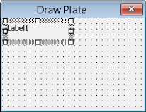
Figure 11.9 The label control added to the user form
The following steps explain how to add two text boxes to the user form:
- In the Toolbox window, use the TextBox icon and place two text boxes. Place a text box to the right of each label.
- Select the first text box placed, the one to the right of the label with the caption
Width:. - In the Properties window, change the following properties of the
TextBox1control to the indicated value:(Name) =txtWidthHeight=18Left=78Width=72 - In the Properties window, change the following property of the
TextBox2control to the indicated value:(Name) =txtHeight - Select the second text box, and then press and hold the Ctrl key. Select the first text box control you placed.
- Right-click over the selected controls and choose Align Lefts.
- Right-click over the selected controls and choose Make Same Size Both.
- Select the first text box control you placed, and then press and hold the Ctrl key. Select the label with the caption
Width:. - Right-click over the selected controls and choose Align Tops.
- Align the tops of the second text box and label.
The following steps explain how to add a check box to the user form:
- In the Toolbox window, click the CheckBox icon and place a check box below the second label.
- In the Properties window, change the following properties of the CheckBox1 control to the indicated values:
(Name) =chkAddLabelCaption=Add LabelHeight=18Left=6Top=48Width=108
The following steps explain how to add two command boxes to the user form:
- In the Toolbox window, use the CommandButton icon and place two command boxes along the bottom of the form below the check box.
- In the Properties window, change the following properties of the
CommandButton1control to the indicated values:(Name) =cmdCreateCaption=CreateDefault=TrueHeight=24Left=42Top=72Width=54 - Change the following properties of the
CommandButton2control to the indicated values:(Name) =cmdCancelCaption=CancelCancel=TrueLeft=102 - Select the second command button, and then press and hold the Ctrl key. Select the first command button you placed.
- Right-click over the selected controls and choose Align Tops.
- Right-click over the selected controls and choose Make Same Size Both.
- Click File Save.
Displaying a User Form
The Show method of a UserForm is used to display it in the AutoCAD drawing environment.
The following steps explain how to create a procedure that displays the user form:
- In the Project Explorer, double-click the
basDrawPlatecomponent. - In the code editor window, scroll to the end of the code editor window.
- Click after the last code statement and press Enter twice. Type the following:
Public Sub DrawPlate() frmDrawPlate.Show End Sub - Click File Save.
- Switch to the AutoCAD application window.
- At the Command prompt, type
vbarunand press Enter. - When the Macros dialog box opens, select the
DrawPlate.dvb!basDrawPlate.DrawPlatemacro from the list and click Run.The Draw Plate user form is displayed in the AutoCAD drawing environment, as shown in Figure 11.10.
- Interact with the controls on the dialog box. Type
acb123in the text boxes and click the command buttons.Notice you can enter text in the text boxes and check the check box. The command buttons don't do anything at the moment, and the text boxes accept any text characters entered with the keyboard.
- Click the Close button in the upper-right corner of the user form.

Figure 11.10 Completed Draw Plate user form in the AutoCAD drawing environment
Implementing Events for a User Form and Controls
Events are used to control what happens when a user clicks a button, types text in a text box, or even when a UserForm is loaded during an AutoCAD session. You will define the Initialize event for the UserForm to assign default values to the text boxes. In addition to setting up the default values for the text boxes, you will define a custom procedure that restricts the user to entering numeric values only into the text values. The custom procedure will be used with the KeyPress event of the text boxes.
The final events you will set up are related to the Click event of the two command buttons. When the Create button is clicked, it will use the values in the user form and prompt the user for the first corner of the plate. The Cancel button dismisses or hides the dialog box without drawing the plate.
The following steps explain how to set up the global variables and constants that will be used by the procedures of the Draw Plate user form:
- In the Project Explorer, right-click the
frmDrawPlatecomponent and choose View Code. - In the code editor window, type the following:
Private myUtilities As New clsUtilities Private g_drawplate_width As Double Private g_drawplate_height As Double Private g_drawplate_label As Boolean ' Constants for PI and removal of the "Command: " prompt msg Const PI As Double = 3.14159265358979 Const removeCmdPrompt As String = vbBack & vbBack & vbBack & _ vbBack & vbBack & vbBack & _ vbBack & vbBack & vbBack & vbLf - Click File Save.
The following steps add the Initialize event for the UserForm and assign the default values to the controls:
- In the code editor window, click the Object drop-down list and choose UserForm. The Object drop-down list is in the upper-left corner of the code editor window.
- Click the Procedure drop-down list and choose Initialize.
- If a procedure other than
UserForm_Initializewas added before step 2, remove the procedure. - Between the
Private Sub UserForm_Initialize()andEnd Subcode statements, type the following:Private Sub UserForm_Initialize() ' Define the width and height for the plate, and enable label placement If g_drawplate_width = 0 Then g_drawplate_width = 5# If g_drawplate_height = 0 Then g_drawplate_height = 2.75 If g_drawplate_label = 0 Then g_drawplate_label = True Me.txtWidth.Text = Format(g_drawplate_width, "0.0000") Me.txtHeight.Text = Format(g_drawplate_height, "0.0000") Me.chkAddLabel.Value = g_drawplate_label End Sub - Click File Save.
The following steps define a custom procedure named ForceNumeric, which restricts input to numeric values only. The procedure is then assigned to the KeyPress event for the txtWidth and txtHeight controls.
- In the code editor window, scroll to the end of the code editor window.
- Click after the last code statement and press Enter twice. Type the following:
Private Sub ForceNumeric(ByRef KeyAscii As MSForms.ReturnInteger)
  If (KeyAscii > 47 And KeyAscii < 58) Or KeyAscii = 8 Or KeyAscii = 32 Then
    KeyAscii = KeyAscii
  ElseIf KeyAscii = 46 Then
    If InStr(1, txtWidth.Text, ".") = 0 Then
      KeyAscii = KeyAscii
    Else
      KeyAscii = 0
    End If
  Else
    KeyAscii = 0
  End If
End Sub
The procedure is passed the ASCII value of the key that is pressed, and if it isn't a number between 0 and 9, a period, a backspace (8), or a carriage return (32), the character returned is a
Nullvalue. - Add the
KeyPressevent for thetxtWidthcontrol and type the text in bold to modify the procedure:Private Sub txtWidth_KeyPress(ByVal KeyAscii As MSForms.ReturnInteger) ForceNumeric KeyAscii End Sub - Repeat step 3 for the
txtHeightcontrol. - Click File Save.
The following steps define the Click event for the Cancel button:
- In the Project Explorer, right-click the
frmDrawPlatecomponent and choose View Object. - In the UserForm editor window, double-click the command button labeled Cancel.
- The code editor, window is displayed and the
Clickevent for thecmdCancelcontrol is added. Type the text in bold to complete the event:Private Sub cmdCancel_Click() Me.Hide End Sub - Click File Save.
The following steps define the Click event for the Create button, which is a variant of the CLI_DrawPlate function.
- Add the
Clickevent to thecmdCreatecontrol. Between thePrivate Sub cmdCreate_ClickandEnd Subcode statements, type the following:Private Sub cmdCreate_Click() Dim oLyr As AcadLayer ' Hide the dialog so you can interact with the drawing area Me.Hide On Error Resume Next Dim sysvarNames As Variant, sysvarVals As Variant sysvarNames = Array("nomutt", "clayer", "textstyle") ' Store the current value of system variables to be restored later sysvarVals = myUtilities.GetSysvars(sysvarNames) ' Set the current value of system variables myUtilities.SetSysvars sysvarNames, Array(0, "0", "STANDARD") ' Get recently used values from the global variables Dim width As Double, height As Double width = Me.txtWidth.Text height = Me.txtHeight.Text ' Prompt for a base point Dim basePt As Variant basePt = Null basePt = ThisDrawing.Utility.GetPoint(, _ removeCmdPrompt & "Specify base point for plate: ") ' If a base point was specified, then draw the plate If IsNull(basePt) = False Then ' Create the layer named Plate or set it current Set oLyr = myUtilities.CreateLayer("Plate", acBlue) ThisDrawing.ActiveLayer = oLyr ' Create the array that will hold the point list ' used to draw the outline of the plate Dim dPtList(7) As Double dPtList(0) = basePt(0): dPtList(1) = basePt(1) dPtList(2) = basePt(0) + width: dPtList(3) = basePt(1) dPtList(4) = basePt(0) + width: dPtList(5) = basePt(1) + height dPtList(6) = basePt(0): dPtList(7) = basePt(1) + height ' Draw the rectangle myUtilities.CreateRectangle dPtList ' Create the layer named Holes or set it current Set oLyr = myUtilities.CreateLayer("Holes", acRed) ThisDrawing.ActiveLayer = oLyr Dim cenPt1 As Variant, cenPt2 As Variant Dim cenPt3 As Variant, cenPt4 As Variant Dim dAng As Double, dDist As Double ' Calculate the placement of the circle in the lower-left corner. ' Calculate a new point at 45 degrees and distance of 0.7071 from ' the base point of the rectangle. cenPt1 = ThisDrawing.Utility.PolarPoint(basePt, PI / 4, 0.7071) myUtilities.CreateCircle cenPt1, 0.1875 ' Calculate the distance between the first and second corners of the ' rectangle. dDist = myUtilities.Calc2DDistance(dPtList(0), dPtList(1), _ dPtList(2), dPtList(3)) ' Calculate and place the circle in the lower-right ' corner of the rectangle. dAng = myUtilities.Atn2(dPtList(2) - dPtList(0), _ dPtList(3) - dPtList(1)) cenPt2 = ThisDrawing.Utility.PolarPoint(cenPt1, dAng, dDist - 1) myUtilities.CreateCircle cenPt2, 0.1875 ' Calculate the distance between the second and third corners of the ' rectangle. dDist = myUtilities.Calc2DDistance(dPtList(2), dPtList(3), _ dPtList(4), dPtList(5)) ' Calculate and place the circle in the upper-right ' corner of the rectangle. dAng = myUtilities.Atn2(dPtList(4) - dPtList(2), _ dPtList(5) - dPtList(3)) cenPt3 = ThisDrawing.Utility.PolarPoint(cenPt2, dAng, dDist - 1) myUtilities.CreateCircle cenPt3, 0.1875 ' Calculate and place the circle in the upper-left ' corner of the rectangle. dAng = myUtilities.Atn2(dPtList(6) - dPtList(0), _ dPtList(7) - dPtList(1)) cenPt4 = ThisDrawing.Utility.PolarPoint(cenPt1, dAng, dDist - 1) Dim oEnt As AcadEntity Set oEnt = myUtilities.CreateCircle(cenPt4, 0.1875) ' Force an update to the last object to display it when ' the dialog reappears. oEnt.Update If Me.chkAddLabel.Value = True Then ' Get the insertion point for the text label Dim insPt As Variant insPt = Null insPt = ThisDrawing.Utility.GetPoint(, _ removeCmdPrompt & "Specify label insertion point " & _ "<or press Enter to cancel placement>: ") ' If a point was specified, place the label If IsNull(insPt) = False Then ' Define the label to add Dim sTextVal As String sTextVal = "Plate Size: " & _ Format(ThisDrawing.Utility. _ RealToString(width, acDecimal, 4), "0.0###") & _ "x" & _ Format(ThisDrawing.Utility. _ RealToString(height, acDecimal, 4), "0.0###") ' Create label Set oLyr = myUtilities.CreateLayer("Label", acWhite) ThisDrawing.ActiveLayer = oLyr Dim oMtext As AcadMText Set oMtext = myUtilities.CreateText(insPt, _ acAttachmentPointMiddleCenter, _ 0.5, 0#, sTextVal) ' Use update to force the display of the label ' as it is the last object drawn before the form ' is redisplayed. oMtext.Update End If End If End If ' Restore the saved system variable values myUtilities.SetSysvars sysvarNames, sysvarVals ' Save previous values to global variables g_drawplate_width = width Me.txtWidth.Text = Format(g_drawplate_width, "0.0000") g_drawplate_height = height Me.txtHeight.Text = Format(g_drawplate_height, "0.0000") g_drawplate_label = Me.chkAddLabel.Value ' Show the dialog box once done Me.show End Sub - Click File Save.
Testing the User Form and Controls
The following steps explain how to test the user form and the DrawPlate procedure in the DrawPlate.dvb file:
- Switch to the AutoCAD application and use the
vbaruncommand to execute theDrawPlate.dvb!basDrawPlate.DrawPlatemacro.The Draw Plate user form is displayed.
- In the Draw Plate user form, in the Width text box, clear the current value and type
abc.Notice the text box ignores the characters
abcas they are being typed. - In the Width text box, clear the current value and type
4. - In the Height text box, clear the current value and type
4. - Clear the Add Label check box.
- Click Create.
- At the
Specify base point for the plate:prompt, pick a point in the drawing area to draw the plate and holes based on the width and height values specified.AutoCAD draws the completed plate without the label, as expected.
- Run the macro again.
- In the Draw Plate user form, select the Add Label check box.
- Click Create and specify the insertion point for the plate and label.
AutoCAD draws the completed plate with a label this time. Figure 11.11 shows the results of the plates drawn with and without the label.

Figure 11.11 Completed plates