
Chapter 3
Floors, Roofs, and Ceilings
This chapter will walk you through the most common horizontal host objects that make up your building. Although the process of creating a floor, roof, or ceiling is somewhat different for each, the tools used to edit each initial design element are similar and have overlapping methodology.
In this chapter, you’ll learn to:
- Create floors by sketching, editing, and picking
- Create sloped floors
- Create and modify a roof by footprint
- Create and modify a roof by extrusion
- Adjust the slope of a roof
- Create ceilings
- Create custom ceilings by sketching
- Add lights to a ceiling
- Slope and modify the ceiling type
Creating Floors
 There are quite a few ways to create floors in the Autodesk® Revit® Architecture software. The main objective for this chapter is to understand what the various approaches to a single floor type will do and what kind of relationships they’ll make.
The objective of the following exercise is to first create floors by sketching the desired shape. Then, for the second part of the exercise you will use the Pick Wall tool to define the floor boundary.
Exercise 3.1: Create a Floor by Sketch and Pick Walls
To begin, go to the book’s web page at www.sybex.com/go/revit2015essentials, download the files for Chapter 3, and open the file c03-ex-3.1start.rvt.
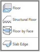
- Open the Level 1 floor plan view. Select the Floor tool on the Build panel of the Architecture tab.
- Revit will automatically enter sketch mode, which will allow you to create a sketch to define the boundary of your floor.
- Create a simple sketch for the floor, 15′ × 30″ (4500 mm × 9000 mm).
- The dimensions are for reference only; even though this is a simple shape, what’s more important is how you can manipulate the shape.
- Confirm that the floor type is Generic − 12″ (Generic − 300 mm) in the Type Selector. Finish the sketch, and open your default 3D view. Your floor should resemble the one shown in Figure 3.1.
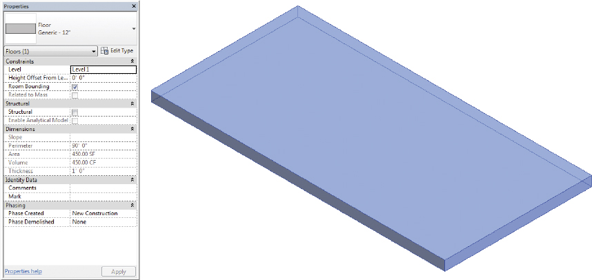
FIGURE 3.1 The finished floor by sketching
- Next, you will create a floor by picking walls. Open the Level 1 view and select the Floor tool on the Build panel of the Architecture tab to enter sketch mode. Select the Pick Walls tool from the Draw palette. Doing so allows you to select an individual wall or an entire chain of walls.
 Move the cursor over one of the wall edges to the right and then press and release the Tab key. Your selection cycles from one wall to the series of walls. When all of the walls highlight, select them with one pick.
- In the Properties palette set the Height Offset From Level parameter to 0″ (0 mm). Click Finish Edit Mode to exit the sketch. Select and move some of the walls that were used to determine the floor sketch. Notice that the boundary of the floor automatically updates (Figure 3.2). This is incredibly powerful for a multistory building, where updating one floor at a time would be nearly impossible.
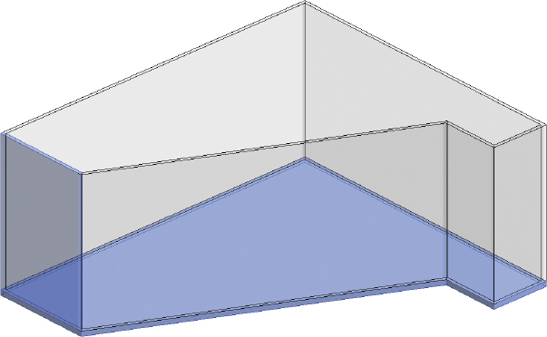
FIGURE 3.2 The finished floor by picking walls
- Note that the edge of the new floor is constructed where you click your mouse when you pick the wall in reference to the interior or exterior of the wall. The floor goes to the outside of the wall; to do that, you have to pick the outside edge of the wall — otherwise, the floor aligns with the interior. The entire chain of sketch lines is created that corresponds to all the walls.
Exercise 3.2: Edit the Floor Boundary
 The objective of the following exercise is to edit and modify an existing floor boundary. To begin, go to the book’s web page at www.sybex.com/go/revit2015essentials, download the files for Chapter 3, and open the file
 c03-ex-3.2start.rvt.
- Open the Level 1 floor plan view, select the floor, and click Edit Boundary from the Modify Floors contextual tab.
- Add additional sketch lines to generate the shape at the lower right in Figure 3.3. Don’t forget to trim back any intersecting lines.
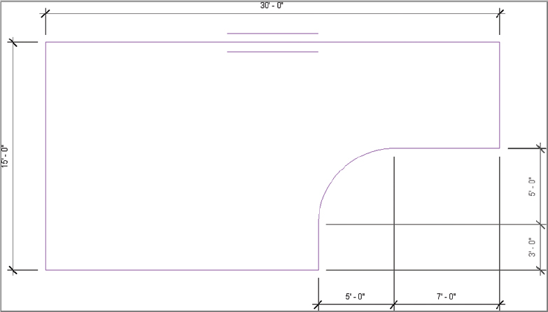
FIGURE 3.3 Modifying the floor sketch
- Finish the sketch by clicking Finish Edit Mode. Select the floor, and notice that the options and dimension properties have already updated, as shown in Figure 3.4.
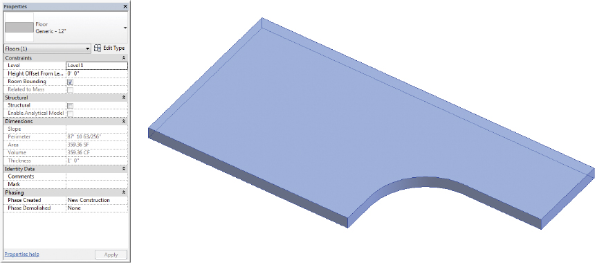
FIGURE 3.4 The modified floor
- Create another floor of the same type and same initial dimensions, 15′ × 30′ (4500 mm × 9000 mm), near the first floor (reference Figure 3.5 for the location). Leave some space between the two floors.
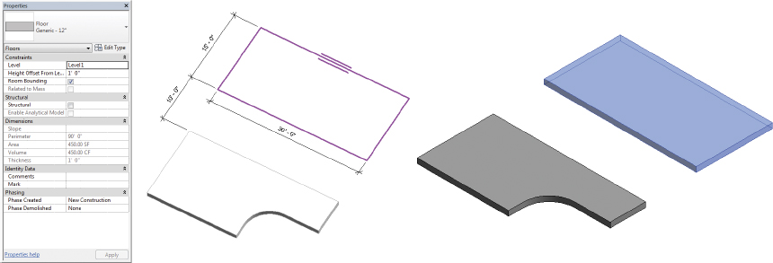
FIGURE 3.5 New floor 1′-0″ (300 mm) above Level 1
- Offset the floor 1′-0″ (300 mm) above Level 1 by entering this value into Height Offset From Level in the Properties palette.
- Finish the sketch to complete the floor (Figure 3.5).
Not all floors are flat, and Revit Architecture has several tools to create sloped conditions. In the following exercise you will investigate both options by creating and modifying sloped floors using two tools: Slope Arrow and Shape Editing.
Exercise 3.3: Create Sloped Floors
To begin, go to the book’s web page at www.sybex.com/go/revit2015essentials, download the files for Chapter 3, and open the file c03-ex-3.3start.rvt.
- Begin by sketching another floor between the two previous floors, filling the gap between the two (Figure 3.6). Set Height Offset From Level to 0″ (0 mm) prior to finishing edit mode.
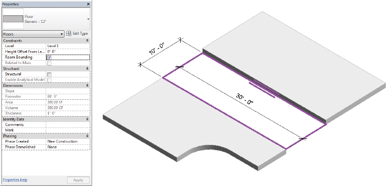
FIGURE 3.6 New floor at Level 1
- If you were to finish the sketch like this, the floor wouldn’t connect the upper and lower sections. You need to add a slope arrow. Do so by selecting the Slope Arrow tool on the Draw panel. Sketch the arrow as shown in Figure 3.7. The first location that you pick is the tail of the arrow; the second location is the head.

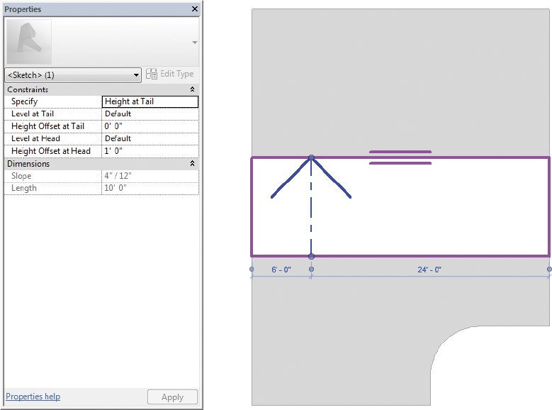
FIGURE 3.7 Slope arrow parameters
- Select the slope arrow, and modify the parameters as shown in Figure 3.7 so they match the location of the upper and lower floors. Be sure to specify the Height Offset for the tail and head.
- Finish the sketch, and return to your default 3D view (Figure 3.8), which shows the finished condition. Now the sloped floor connects the lower and upper floors.
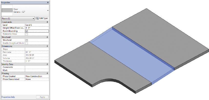
FIGURE 3.8 Completed sloped floor
- You could create slightly sloped floors and depressions with slope arrows and separate floors, but this approach would probably be too complex because you’d have to create a lot of separate pieces of geometry. For these kinds of conditions, you have the Shape Editing tools.
- Select the upper floor. Now you can see the Shape Editing tools in the Shape Editing panel on the Modify Floors tab.
- Let’s suppose that this entire floor is at the correct level, except for one small portion that needs to be slightly depressed in order to accommodate a loading area. Define the upper and lower boundaries of this depressed area by selecting the Add Split Line option on the Shape Editing panel. Add the lines as shown in Figure 3.9. Dimensions are shown for reference.
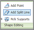
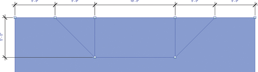
FIGURE 3.9 Adding split lines
- Now that you’ve added the proper locations to break the slope, you need to modify the points at the ends of the lines to change the slope of the floor. Start by returning to your default 3D view. As you hover over the endpoint of the line, Revit Architecture highlights the shape handles. Press the Tab key to highlight a specific handle, and then select it (Figure 3.10).
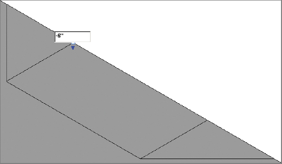
FIGURE 3.10 Editing the shape handle
- Adjust the elevation of the shape handle as shown in Figure 3.10. In this case, you’re depressing the floor, so the value must be negative. But you could also increase the elevation in a small area by using a positive value.
- Do the same for the shape handle to the right. When you’ve finished, the depressed area resembles Figure 3.11.
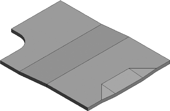
FIGURE 3.11 The finished depression
For the occasional or irregular opening in a floor, it’s easy to add an opening using the Opening tools. For openings that occur from level to level and are vertically repetitive (such as a shaft or an elevator core), you can use the Shaft tool. This tool allows you to create openings in numerous floors, roofs, and ceilings quickly and easily.
The objective of the following two exercises is to create openings in your floor objects. The first exercise will focus on the Opening By Face tool. The second exercise will focus on the Shaft Opening tool.
Exercise 3.4: Create an Opening with the Opening by Face Tool
To begin, go to the book’s web page at www.sybex.com/go/revit2015essentials, download the files for Chapter 3, and open the file c03-ex-3.4start.rvt.
- From the Architecture tab on the ribbon, select the Opening By Face tool on the Opening panel.

- Select any edge of the sloped floor you created to initiate sketch mode.
- Sketch an opening 10′ × 3′ (3000 mm × 1000 mm) in the center floor panel. There’s no limit to the number of interior sketches you can create.
- Click Finish Edit Mode to complete the sketch. The result resembles Figure 3.12.
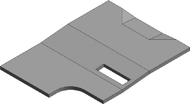
FIGURE 3.12 The finished opening
- You can also edit previously created sketches by selecting the opening and clicking Edit Boundary from the ribbon. An opening of this type remains perpendicular to the slope of the floor, roof, or ceiling. On the other hand, a vertical opening remains perpendicular to the level on which it was created.
- Select the Vertical tool from the Opening panel, and sketch a new opening of the same size and dimensions above the first one. The result resembles Figure 3.13.

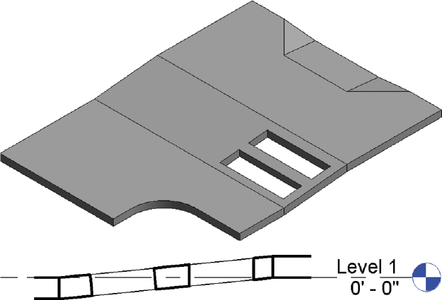
FIGURE 3.13 Completed openings of the same size and dimensions
The differences are subtle but very important. By creating a section through both openings, you can see the difference in an opening that remains perpendicular to the floor compared to one that remains perpendicular to the level (Figure 3.13).
Exercise 3.5: Create an Opening with the Shaft Opening Tool
To begin, go to the book’s web page at www.sybex.com/go/revit2015essentials, download the files for Chapter 3, and open the file c03-ex-3.5start.rvt.
This example file has 10 total levels, which are evenly spaced.
- Select all three floors on Level 1, and copy them to the clipboard. Now the geometry is ready to be pasted to each of the levels.

- The best way to do this is by using the Paste tool, which allows you to select all the levels to which you intend to paste the floors.
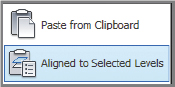
- Click the Paste drop-down from the Clipboard panel of the Modify | Floors tab, and then select Aligned To Selected Levels.
- You’re given the option to select all the levels: Select Levels 2–10 (Figure 3.14). The resulting floors are shown in the same figure.
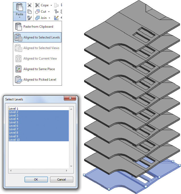
FIGURE 3.14 Pasted geometry
- Return to the Level 1 view, and select the Shaft Opening tool from the Opening panel.
- Create a new 20′ × 3′ (6100 mm × 1000 mm) rectangle perpendicular to the last two you drew.
- Confirm that the Top Constraint is set to Level 10 so the shaft goes up to the top floor. Then set the Top Offset to a minimum of 1′ (300 mm) to ensure it fully cuts the floor. A higher value can be specified as needed.
- Be certain to assign a Base Offset value of -1′ (-300 mm), because the upper floor is slightly above the level (Figure 3.15).
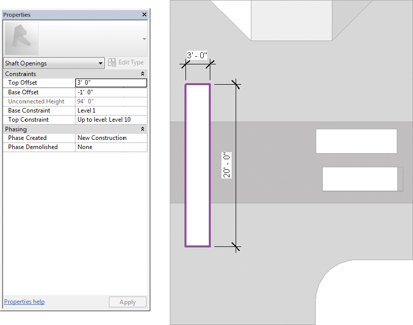
FIGURE 3.15 Creating a multistory shaft
Figure 3.16 shows the resulting shaft in 3D. All the floors were cut automatically. Any ceilings, roofs, and additional floors created later that are between the same levels will be cut automatically as well.
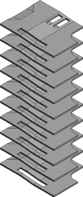
FIGURE 3.16 The finished multistory shaft
Creating Roofs
There are two primary methods for creating roofs, which you will explore in this chapter: Roof by Footprint and Roof by Extrusion. You create a Roof by Footprint roof much like you do floors: from a sketch resulting from either drawn lines or picked walls. And as with floors, if you pick the exterior walls as a reference, then moving the walls will move the corresponding edges of the roof. Roofs can be created in elevation using the Roof by Extrusion tool, which we will cover in the second exercise.
The objective of the following exercise is to create a roof by picking the outline of existing walls.
Exercise 3.6: Create a Roof by Footprint
To begin, go to the book’s web page at www.sybex.com/go/revit2015essentials, download the files for Chapter 3, and open the file c03-ex-3.6start.rvt.
- Open the Level 1 plan view. Select the Roof by Footprint command from the Roof flyout on the Architecture tab. At this point, Revit Architecture automatically asks you to select the level with which this roof is associated.
- Select Level 3. Don’t worry; you can change the level at any time later.
- Again, you don’t have to pick all the walls individually or sketch all the roof boundary lines.
- Select the Pick Walls option on the Draw panel of the Modify | Create Roof Footprint tab. Uncheck the Defines slope setting on the Options Bar.
- Move the cursor over one of the exterior walls and press the Tab key until the entire chain is highlighted; then left-click. All the roof boundary lines will be created.
- Because this will be a sloped roof, you can make the slope perpendicular to the left edge by checking the Defines Slope box on the Options Bar or the Properties palette.

- Define the Slope property for this roof sketch line with a 1″ / 12″ (83 mm / 1000 mm) rise over run (Figure 3.17).
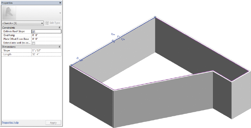
FIGURE 3.17 Roof sketch and slope properties
- Finish the sketch, and look at the project in 3D.
- Although the roof begins at Level 3 and has the proper slope, it’s immediately obvious that the walls don’t extend up to the roof.
- To resolve this condition select all the walls (using the Tab key to select the entire chain), and set Top Constraint to Level 4 in the Properties palette. The results resemble Figure 3.18.
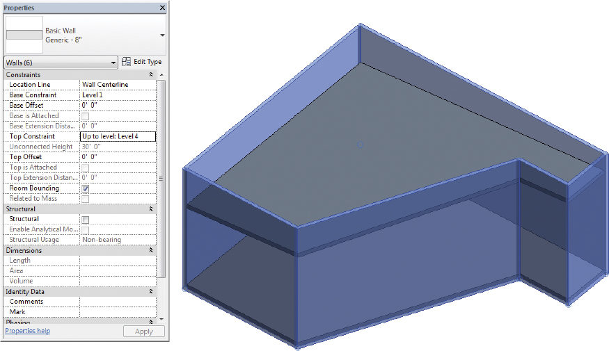
FIGURE 3.18 Adjusting the wall height
The objective of the following exercise is to create an extruded roof and join it to an existing roof.
Exercise 3.7: Create a Roof by Extrusion
To begin, go to the book’s web page at www.sybex.com/go/revit2015essentials, download the files for Chapter 3, and open the file c03-ex-3.7start.rvt.
- Select the Roof by Extrusion command from the Roof flyout on the Architecture tab. The Work Plane dialog should prompt you to specify a new work plane. Choose the Pick a plane option and select the roof face highlighted in Figure 3.19.
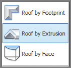
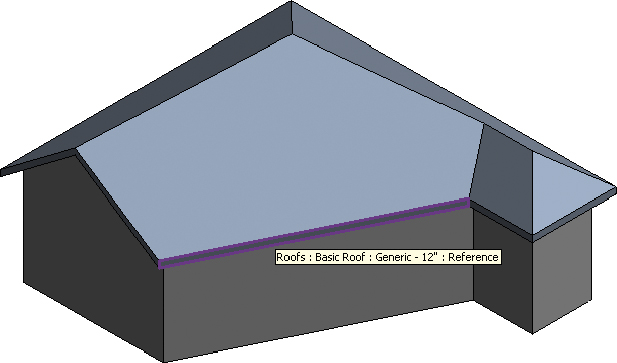
FIGURE 3.19 Selecting the roof face
- You’re prompted to associate the roof to the appropriate level. This step is important for scheduling purposes; you can modify the value later. For now, select Level 3 because it’s closest to the base of the extruded roof.
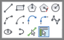
- Next, you’ll create the sketch for the extruded roof. The sketch line isn’t a closed loop: It’s just a line (or series of connected lines) that defines the top of the extruded roof. For this example, you’ll create an arc. Select any of the Arc tools from the Draw panel.
- Create the arc approximately as shown in Figure 3.20. When you’ve finished drawing the arc, set Extrusion End in the Properties palette to 20′-0″ (6100 mm).
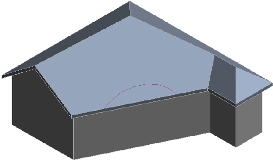
FIGURE 3.20 Creating the arc
- Finish the sketch. The roof springs from the arc you created, but it’s not reaching back and connecting to the roof face. This issue is easy to resolve.
- Select the roof extrusion, and then select the Join/Unjoin Roof tool on the Geometry panel.
- Hover over the rear edge of the extruded roof, as shown in the left image of Figure 3.21.
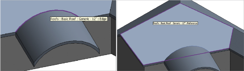
FIGURE 3.21 Attaching the roof
- Select the face of the previously created roof that you want to connect to the extruded roof. The extruded roof now extends back to meet the face of the other roof (Figure 3.22). If either roof is modified, Revit Architecture will do its best to maintain this connected relationship.
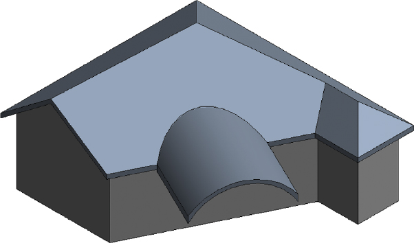
FIGURE 3.22 Joined roofs
You can determine the slope of a roof using slope arrows. Slope arrows let you specify a slope, and they also allow you to specify the levels of the arrow at both the head and tail.
The objective of the following exercise is to modify an existing roof condition using slope arrows to adjust the resulting slope.
Exercise 3.8: Create Slope Arrows
To begin, go to the book’s web page at www.sybex.com/go/revit2015essentials, download the files for Chapter 3, and open the file c03-ex-3.8start.rvt.
- Select the roof, and click Edit Footprint on the ribbon to enter sketch mode.
- The tail of the slope arrow must reside on the boundary of the sketch, but the head of the slope arrow may point in practically any direction. Select the Slope Arrow tool on the Draw panel, and add a slope arrow as shown in Figure 3.23. Note that the Height Offset at Head value is set to 6′ (2000 mm).

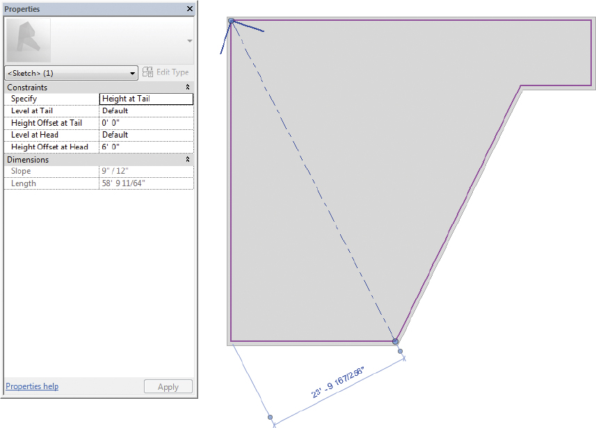
FIGURE 3.23 Sloping the roof
- Make sure you uncheck the Defines Slope option for the edges of the roof to see the full effect of using the slope arrow (Figure 3.23).
- Finish the sketch. Notice that a single slope proceeds across the roof. A single slope in this direction would be nearly impossible to specify without slope arrows.
- You can also create roof slopes using multiple slope arrows. This technique is incredibly helpful when you want to create sloped conditions where two perpendicular slopes must meet at exactly the same location. Again, this is something that’s difficult to do without slope arrows.
- Select the roof and click Edit Footprint to reenter sketch mode. Delete the existing slope arrow.
- Sketch two new slope arrows along the north—south and east—west roof boundary edges so that the heads of the arrows meet at the upper-left corner. The slope arrows should have the following properties:
- Set Height Offset at Tail to 0″ (0 mm).
- Set Height Offset at Head to 6′-0″ (2000 mm).
- Make sure Height Offset is the same for both tails and both heads. Finish the sketch. The results resemble the roof in Figure 3.24.
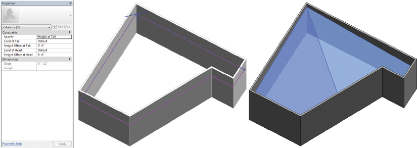
FIGURE 3.24 Roof created from two slope arrows
The objective of the following exercise is to create multiple slopes that are perpendicular to the edges using the Defines Slope option.
Exercise 3.9: Create Multiple Roof Slopes
To begin, go to the book’s web page at www.sybex.com/go/revit2015essentials, download the files for Chapter 3, and open the file c03-ex-3.9start.rvt.
- Select the roof and click Edit Footprint to reenter sketch mode for the roof. Delete both slope arrows.
- Select all the lines that represent the roof sketch. You can do this by holding down Ctrl and selecting the lines individually or by clicking one line and pressing Tab to select the rest of the lines.
- With the lines selected, in the Options Bar enter 3′ (1000 mm) for the overhang. The overhang direction will move positive in relation to the side of the wall picked (exterior or interior). Positive or negative dimensions can be entered if the sketch moves in the opposite direction. Also keep in mind that the Overhang option is available only for roof sketch lines created using the Pick Walls option.
- Select the Defines Roof Slope option for all the boundary edges from the Properties palette. Also modify the Slope property for a slope of 9″ / 12″ (750 mm / 1000 mm). The roof should look like Figure 3.25.
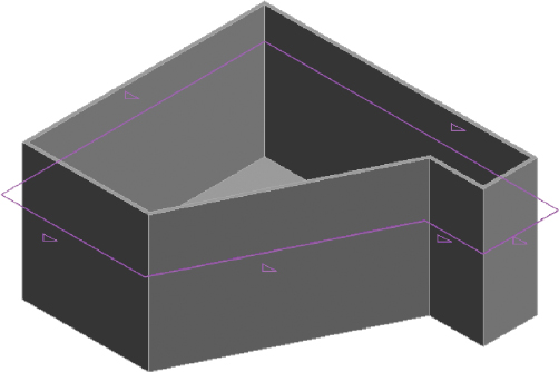
FIGURE 3.25 Offsetting the roof sketch and defining slopes
 Finish the sketch. Initially, the edges of the wall extend beyond the overhang of the roof. Select all the exterior walls (use the Tab key), and then select the Attach Top/Base option on the Modify | Walls tab. Click the roof to attach it, and the result resembles Figure 3.26.
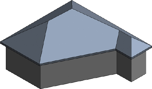
FIGURE 3.26 Attaching the walls to the roof
- The great thing about attaching walls is that if the roof’s angle or slopes change, the walls will automatically react to the new condition. To test this, select the roof and click Edit Footprint to reenter sketch mode. Remove the Defines Slope option for one of the edges.
- Finish the sketch, and the results resemble Figure 3.27. Because the walls were previously told to attach to the roof, a gable condition is created.
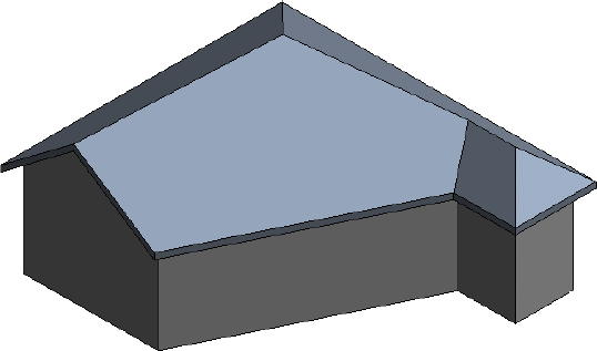
FIGURE 3.27 Removing a defined slope
- Reenter sketch mode, and enable Defines Slope for the same gable sketch line.
- Select the sketch line, and locate the option Plate Offset From Base in the Properties palette. Change the value to 6′-0″ (1800 mm) and finish the sketch.
- Notice that the roof edge is offset from the base and the slope starts at the offset dimension. This is another powerful approach to modify the roof shape.
Adding Ceilings
Ceilings in Revit Architecture are easy to place as well as modify. As you move the walls, the ceiling associated to those walls will stretch to fit the new conditions. There are two different tools to create ceilings in Revit Architecture:
Automatic Ceiling Tool The Ceiling tool is on the Build palette of the Architecture tab. When you select the tool, the default condition is Automatic Ceiling. This means that as you hover over a space, Revit Architecture will attempt to find the boundary of walls.
Sketch Ceiling Tool The Sketch Ceiling tool is useful for customized conditions, such as a ceiling soffit or bulkhead where it is necessary to draw the boundary, or simply for boundaries where the ceiling objects do not span the entire space.
The objective of the following exercise is to first create ceilings automatically. Then you will create a more custom, sketch-based ceiling.
Exercise 3.10: Add Automatic and Sketch Ceilings
To begin, go to the book’s web page at www.sybex.com/go/revit2015essentials, download the files for Chapter 3, and open the file c03-ex-3.10start.rvt.
- Using the Automatic Ceiling option, add a ceiling toward the bottom of the image (Figure 3.28). As you hover over the space, Revit Architecture indicates the boundary.
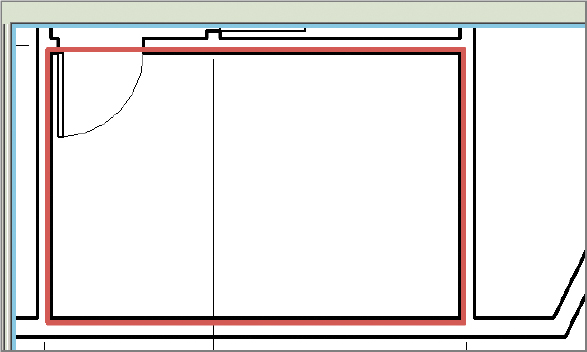
FIGURE 3.28 Revit Architecture outlines the boundary.
- As you can see from the Properties dialog, Revit Architecture offers four default ceiling types: one basic type and three compound types. Select the 2′ × 2′ (600 mm × 600 mm) system.
- When you click to place the first ceiling in the floor plan view, you get a warning. This can happen frequently: You’ve placed the ceiling, but you can’t see it. As a rule, you shouldn’t ignore warnings because you could place multiple ceilings in the same place. Open the view Ceiling Plans - Level 1, which has ceiling objects visible.
- Select the Ceiling tool on the Architecture tab, and pick inside the rooms shown in Figure 3.29 to automatically place the ceilings. Notice that Revit Architecture centers the grid based on the space you’ve selected.
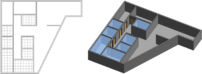
FIGURE 3.29 Resulting automatic placed ceilings
- Next, you’ll place ceilings in the upper-left corner of the ceiling plan for Level 1, but this time you’ll share the ceiling between the two spaces. This practice is common in interior projects. The partitions extend only to the underside of the ceiling (rather than connect to the structure above). Select Sketch Ceiling on the Ceiling panel of the Modify | Place Ceiling tab. Add sketch lines as shown in the first image in Figure 3.30. The result is shown in the second image.
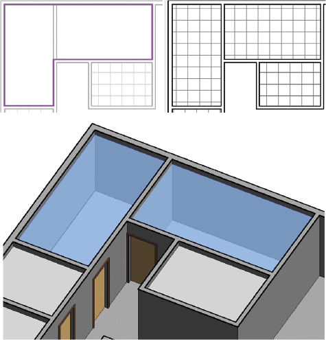
FIGURE 3.30 Sketching the ceiling
- Create another ceiling using Sketch Ceiling in the upper-right area of the plan (Figure 3.31). Choose the 2′ × 4′ (600 mm × 1200 mm) system from the Type Selector before you finish the sketch of the ceiling.
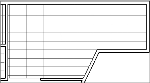
FIGURE 3.31 A 2′ × 4′ (600 mm × 1200 mm) ceiling
- Create a GWB on Mtl. Stud Ceiling for the area shown in Figure 3.32.
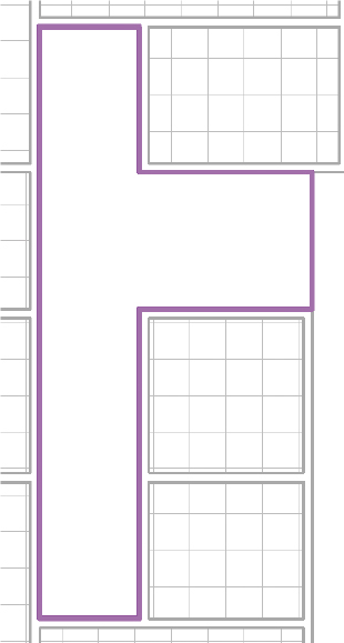
FIGURE 3.32 Creating a GWB On Mtl. Stud Ceiling
- By default, the GWB material doesn’t have a surface pattern. Although this material would be too graphically busy for walls, it’s fine for ceilings. So, let’s create a new material for GWB associated to ceilings and give it a pattern.
- Select the ceiling, and click Edit Type from the Properties palette. Click the Structure Edit button from the Type Properties dialog to open the Edit Assembly window.
- Locate the Finish layer, and then under the Material column, click in the cell for Gypsum Wall Board. Click the ellipsis (...) button that appears in the cell to open the Material Browser. Right-click and duplicate the existing material. Rename the new material Gypsum Ceiling Board.
- On the Material Graphics tab, locate Surface Pattern and associate the surface pattern called Sand to the material.
- Click OK until you close all the dialog boxes and return to the ceiling plan view.
- The result is shown in Figure 3.33. You can now distinguish the ceiling from the open areas that have no ceiling.
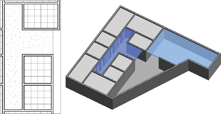
FIGURE 3.33 Assigning materials to a ceiling
- The result is shown in Figure 3.33. You can now distinguish the ceiling from the open areas that have no ceiling.
The objective of the following exercise is to create a bulkhead condition to separate two ceilings.
Exercise 3.11: Create a Bulkhead
To begin, go to the book’s web page at www.sybex.com/go/revit2015essentials, download the files for Chapter 3, and open the file c03-ex-3.11start.rvt.
- Place the walls that will act as the bulkhead, as shown in Figure 3.34. Be sure to set the Base Offset value in the Properties palette of the walls to 7′-9″ (2400 mm) and the Unconnected Height value to 2′-3″ (700 mm). This creates two walls above head height.
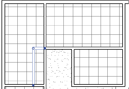
FIGURE 3.34 Creating a bulkhead
- The easiest method to edit a ceiling is to select a grid line and choose Edit Boundary from the Mode panel on the Modify | Ceilings tab. Modify the ceiling as shown in the first image in Figure 3.35.
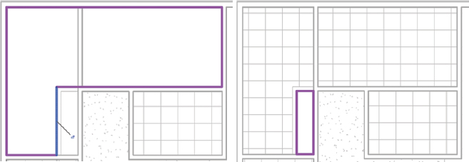
FIGURE 3.35 Editing the boundary
- Sketch a new GWB ceiling that is 9′-0″ (2700 mm). The second image in Figure 3.35 shows the final ceiling shape before you will click Finish Edit Mode.
- Click Finish Edit Mode.
- To get a better idea of the finished configuration in 3D, go to a 3D view and orient a section box of the Level 1 plan view.
- Right-click the ViewCube, and from the Floor Plans flyout of the context menu, select Level 1.
- Orbit the view or use the ViewCube to choose the desired angle.
- Use the grip arrows to pull the boundaries of the section box to resemble Figure 3.36. You’ll find that working this way is helpful because having both 2D and 3D views aids in communicating any design issues.
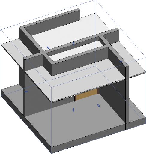
FIGURE 3.36 Final section box location in 3D view
The objective of the following exercise is to add light fixtures hosted to the ceiling. Then for the second part of the exercise you will rotate the ceiling grid.
Exercise 3.12: Add Lights and Rotate the Grid
To begin, go to the book’s web page at www.sybex.com/go/revit2015essentials, download the files for Chapter 3, and open the file c03-ex-3.12start.rvt.
- On the Insert tab, select Load Family on the Load From Library panel.
- Browse and open the
LightingArchitecturalInternalfolder, and double-click the familyCeiling Light — Linear Box.rfa(M_Ceiling Light — Linear Box.rfa). - Click the Place a Component button, and the ceiling light family should be the default.
- Select the 2′ × 4′ (2 Lamp) − 120V (0600 mm × 1200 mm) type from the Type Selector. You’ll place lighting fixtures into the 2′ × 4′ (0600 mm × 1200 mm) ceiling in the upper-right ceiling plan.
- The insertion point for the light is the center of the light. Place the first light, and then use the Align tool to move it into the right spot.
- Use the Copy tool on the Modify panel to copy the first light based on the intersection of the ceiling grid. All the lights are shown in Figure 3.37.
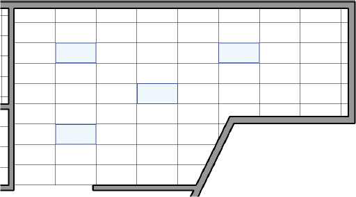
FIGURE 3.37 Placing lights
- To rotate the grid, select any grid line, and use the Rotate tool on the Modify panel to rotate it. In this case, specify a 10-degree angle. Notice that the lights rotate as well.
- Click and drag the ceiling grid lines to better center the lights in the overall space. Again, the lights move with the grid. The Move, Align, and Rotate tools are all available to modify ceilings when a grid line is selected.
- This technique is incredibly helpful for maintaining design coordination. The finished condition is shown on the right in Figure 3.38.
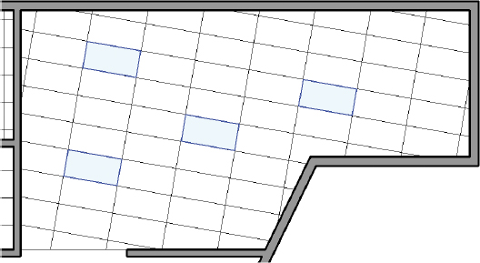
FIGURE 3.38 Rotated ceiling grid
- This technique is incredibly helpful for maintaining design coordination. The finished condition is shown on the right in Figure 3.38.
The objective of the following exercise is to slope the ceiling by placing a slope arrow while editing the boundary of the ceiling. You will also change the ceiling type during this exercise.
Exercise 3.13: Slope the Ceiling
To begin, go to the book’s web page at www.sybex.com/go/revit2015essentials, download the files for Chapter 3, and open the file c03-ex-3.13start.rvt.
- First, select the ceiling and using the Type Selector in the Properties palette change the ceiling type to GWB on Mtl. Stud. Notice that the ceiling updates to reflect the new ceiling type.
- Select the edge of the ceiling, and choose Edit Boundary on the Mode panel on the Modify | Ceilings tab.
- Place a slope arrow as shown in the top image in Figure 3.39. Set the Height Offset values for the Tail and Head to 0′-0″ and 3′-0″ (1000 mm), respectively.
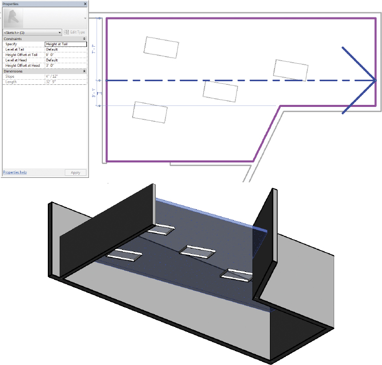
FIGURE 3.39 Adding a slope arrow to the ceiling
- Finish the sketch. The result (bottom image in Figure 3.39) is shown in 3D using a section box. The lights should follow the revised ceiling slope.