Chapter 6
Modifying Families
Now that you have added a number of families to your project and the design has progressed, you’ll often find it necessary to modify the families. Sometimes swapping out a generic family component for one that is more specific is the best solution. In other cases, it’s simply a matter of opening the component family that you started with and tweaking the geometry to better fit your design. Either solution is viable—which you choose depends on the result that is better for your design process.
In this chapter, you’ll learn to:
- Modify family categories
- Edit component families
- Edit profile families
- Place and modify detail components
- Edit a title block family
- Edit other hosted component families
- Explore various family tips and best practices
Modifying 3D Families
As you learned in Chapter 5, “Adding Families,” finding and placing content is pretty straightforward, but learning to modify it will take a bit more time. One of the first things you want to consider when loading a family into your project is the level of detail the family displays at different orientations and scales. It’s not likely that every part of a component family needs to display at all scales. It’s more likely that too much detail will be confusing (particularly at smaller scales). Just a decade or so ago, when we used pencils, knowing when to stop drawing detail was pretty easy. But high-resolution computer displays that give you the ability to zoom in and out, as well as modern printing technologies, have allowed us to create far more detail than is necessary or meaningful. So, how do you display just the right level of detail in the Autodesk® Revit® Architecture software? In this chapter, we’ll explore some fundamental techniques you can use to modify families to meet your needs.
In the following exercise you will work with different zoom levels to optimize the view for how information will be displayed. For the second part of the exercise you will change the view detail level and note visibility changes.
Exercise 6.1: View Scale and Detail Level
To begin, go to the book’s web page at www.sybex.com/go/revit2015essentials, download the files for Chapter 6, and open the file c06-ex-6.1start.rvt.
- The exercise file should open to the South elevation view. Zoom to the desk by right-clicking in the view and selecting Zoom To Fit. This will show you everything in your view; however, it doesn’t give you a sense of what will be legibly printed (Figure 6.1).
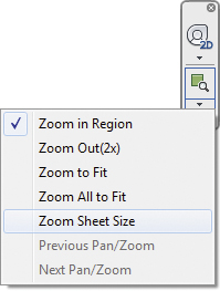
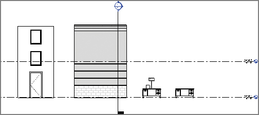
FIGURE 6.1 Zoom To Fit
- The best method to confirm what will be graphically legible when you print is to click the down arrow on the Navigation bar (on the right side of the view) and select the Zoom Sheet Size option. Doing so will take the scale of the view into account when zooming in (or out). The difference is shown in Figure 6.2.
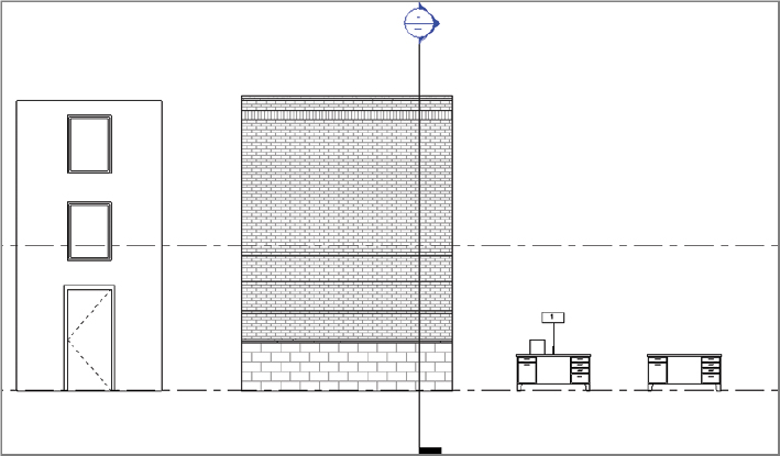
FIGURE 6.2 Zoom Sheet Size
- Open the Desk elevation view and change the scale in the View Control Bar to 1/2″ = 1′-0″ (1:20), and then click the Zoom Sheet Size button under the Navigation bar again. You may need to pan the view slightly depending on where it zoomed.
- You will see a more visible difference in what is displayed on the screen relative to the scale of the view. Notice in both the previous figures that the hardware on the desk is completely visible in both views.
- Next, change the scale to 1″ = 40′-0″ [1:50], 1″ = 20′-0″ [1:20], and lastly 1″ = 10′-0″ [1:10]. You can see the change in the desk’s appearance at different scales (Figure 6.3).
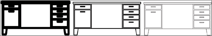
FIGURE 6.3 Elevation at different scales
- As you can see, all the geometry of the desk—drawers and hardware—is visible at all view scales. But it doesn’t have to be this way. A good rule of thumb is that if two lines are overlapping to the point that they’ll print like a single line, they probably don’t need to be seen.
- To adjust the settings for displaying information at different scales, navigate to the Manage tab under Additional Settings
 Detail Level, as shown in Figure 6.4. Click OK to close the dialog when complete.
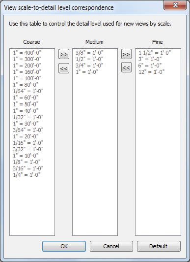
FIGURE 6.4 View Scale-To-Detail Level Correspondence settings
- Let’s look at another example of how the detail level controls the visibility of families:
- Open the elevation view named Cabinet. This view displays a cabinet family with the other objects hidden in the view.
- The detail level of the view is currently set to Coarse. Change the detail level from Coarse to Medium and notice what happens. You now see the cabinet panels and swing lines in the view (Figure 6.5).
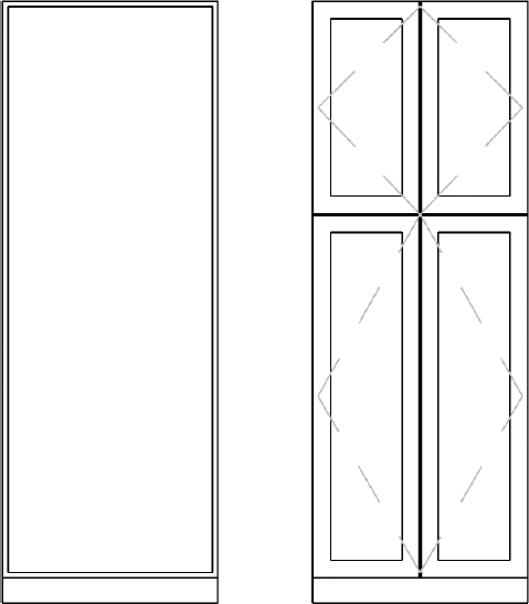
FIGURE 6.5 Coarse and Medium detail levels
- Change the detail level from Medium to Fine and note what happens again. You now see the cabinet hardware that was not visible in Coarse or Medium detail (Figure 6.6).
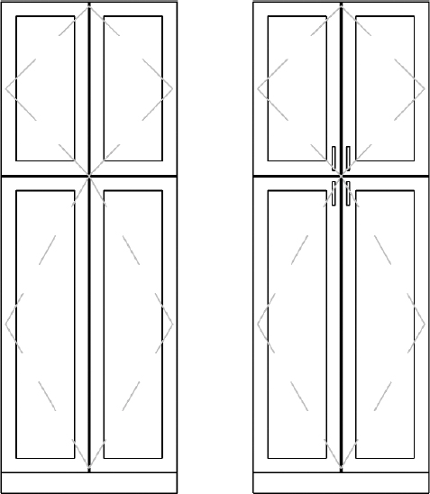
FIGURE 6.6 Medium and Fine detail levels
So what controls which elements display in a family at a specific detail level? In the following exercise you will edit a family and assign geometry visibility to specific detail levels, reproducing the same family from scratch.
Exercise 6.2: Assign Visibility to Detail Levels
To begin, go to the book’s web page at www.sybex.com/go/revit2015essentials, download the files for Chapter 6, and open the file c06-ex-6.2start.rvt.
- From the Level 1 view select the cabinet family, and choose Edit Family from the Mode panel of the ribbon (or right-click and choose Edit Family from the context menu).

- From the 3D view select the hardware (cabinet face handles) on the front of the cabinet. Click the Visibility Settings button on the Modify tab of the ribbon to open the Family Element Visibility Settings dialog box (Figure 6.7).

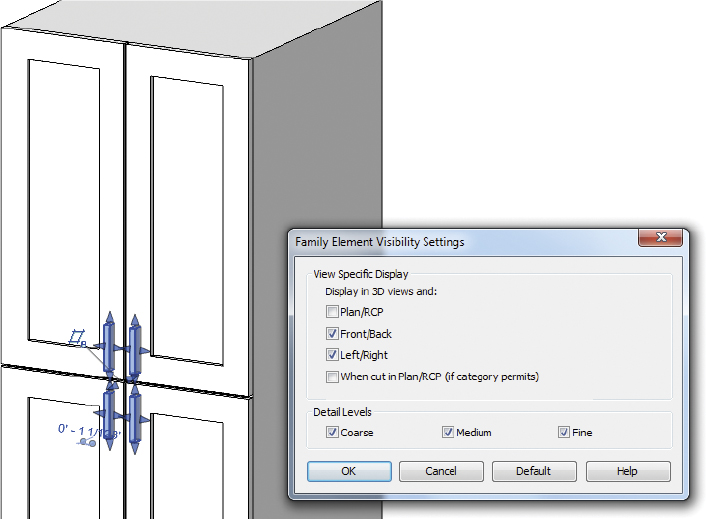
FIGURE 6.7 Editing levels of detail for hardware
- This dialog box allows you to determine the visibility for both the orientation and level of detail for the hardware. Currently the hardware shows up at all levels of detail (Coarse, Medium, and Fine).
- Change the settings so that it shows up only at a Fine level of detail by unchecking Coarse and Medium (Figure 6.8).
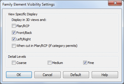
FIGURE 6.8 Set Detail Levels to Fine only
- Select both cabinet face panel extrusions (there are two separate extrusions that make up the front of the cabinet: the border and the recessed panel). Change the visibility settings so they show up at the Medium and Fine levels of detail but not Coarse.
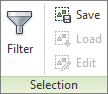
- Next, you want to do the same for the model lines since they also display in 3D views. An easy way to select only the model lines is to use the Filter tool. Select everything in the 3D view and click Filter from the Selection ribbon panel.
- Click Check None, and then check Lines (Casework). Click OK to return to the model with only the lines selected (Figure 6.9).
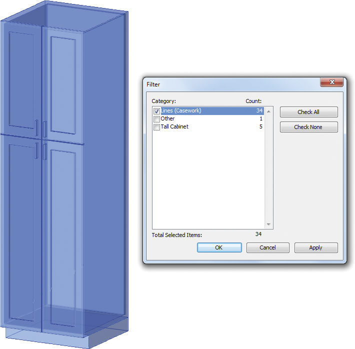
FIGURE 6.9 Using Filter for selection
- Click the Visibility Settings button on the Modify tab of the ribbon and uncheck Coarse. Click OK to return to the model. Next, you want to select just the lines around the hardware extrusions. From the same 3D view window, select around the hardware and use the Filter tool again to select just Lines (Casework). Open the Family Element Visibility Settings dialog again and also uncheck Medium so only Fine is checked (Figure 6.10).

FIGURE 6.10 Window selection and filter
- Open the Front Elevation view. Select the dashed elevation swing lines (eight of them) and click Visibility Settings from the ribbon. Uncheck Coarse so you also do not see these lines in the project when the cabinet doors are not visible.
- On the Modify tab of the ribbon, click the Load Into Project button to reload the cabinet family into the project. Click Overwrite The Existing Version when prompted.
- Back in the project the last step is to open the Cabinet elevation view where you can see the front of the cabinet. Change the detail level to Coarse. The cabinet lines, panels, and hardware should not be visible. Change the detail level to Medium, and you should see panels plus the dashed lines. Change the detail level to Fine, and you should also see the hardware (Figure 6.11).
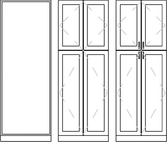
FIGURE 6.11 Cabinet appearances for detail levels
Family Categories
Family components schedule according to their category, which is determined when you start to model a new family component. When you create a new family component, you must first select the appropriate template.
It is important to differentiate between the category of the family and the template that the family was created with. While the family category can be changed later, the type of host cannot be changed afterward. For example, several generic model family templates are available when creating a new family, such as the following examples:
Generic Model ceiling based.rftGeneric Model face based.rftGeneric Model floor based.rftGeneric Model roof based.rftGeneric Model wall based.rft
If you start a new family with Generic Model floor based.rft, you can always change the category from Generic Model to Furniture. However, it is not possible to change the host from floor to wall-hosted. The Host family parameter is fixed according to the starting template.
In the following exercise you will change the category of an existing family and load it back into the project.
Exercise 6.3: Edit the Family Category
To begin, go to the book’s web page at www.sybex.com/go/revit2015essentials, download the files for Chapter 6, and open the file c06-ex-6.3start.rvt.
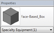
- From the 3D view select and right-click the face-based box, and choose Edit Family from the context menu.
- When the Family Editor opens, notice the “platform” the box is sitting on. This is the context for the “face” of the face-based family (Figure 6.12). Face-based and hosted families already have geometric context (along with critical parameters and reference planes) in their templates so you can model in context and test parametric behavior.
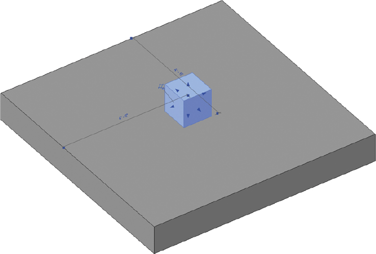
FIGURE 6.12 Editing the face-based family
- When this component was initially created, it needed to be face-based. So, the default face-based template was used,
Generic Model face based.rft. Since the family category has never been modified, it is still configured using the original Generic Models category. Now let’s assume the design has progressed and the component needs to schedule as Specialty Equipment.
- When the Family Editor opens, notice the “platform” the box is sitting on. This is the context for the “face” of the face-based family (Figure 6.12). Face-based and hosted families already have geometric context (along with critical parameters and reference planes) in their templates so you can model in context and test parametric behavior.
- Go to the Create tab’s Properties panel, and click Family Category and Parameters.

- When the Family Category and Parameters dialog box appears, the current category is selected. Select Specialty Equipment from the list (Figure 6.13), and click OK.
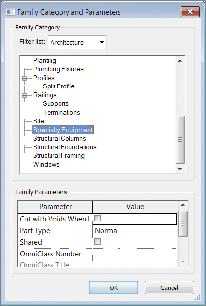
FIGURE 6.13 Changing the family category
- Click Load into Project from the Modify tab on the ribbon to reload the family into the project environment.
- Select the option to override the existing version.
- The family doesn’t appear to have changed, but it now schedules according to its new category.
- To confirm the updated category move your cursor over the family, and the tooltip should display the updated family category.
In the following exercise you will update the origin of a family for both plan and elevation. Then you will load the updated family back into the project.
Exercise 6.4: Update a Family Insertion Point
To begin, go to the book’s web page at www.sybex.com/go/revit2015essentials, download the files for Chapter 6, and open the file c06-ex-6.4start.rvt.
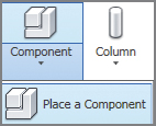 Open the Level 1 plan view. Go to the Architecture tab’s Component flyout, and click Place a Component.
- From the Modify | Place Component contextual tab, click the Load Family button; under the
Furniturefolder,Seatingsubfolder, choose theChair-Executive.rfa(M_Chair-Executive.rfa) family. Place it as shown in the left image in Figure 6.14, making sure the chair is centered under the desk’s opening.
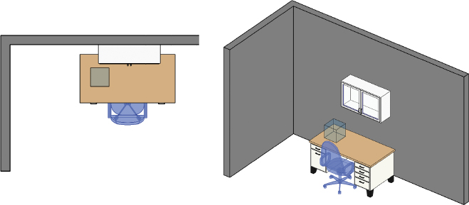
FIGURE 6.14 Loading and placing the chair in the project
- Select the desk. In the Type Selector, choose the 72″ × 36″ (1830 × 915 mm) type.
- The changes in the desk dimensions are applied from the upper-right corner; therefore, the chair is no longer centered and will have to be moved. If there were many chairs and desks in this situation (such as in an office layout), this task would be very tedious! Let’s change the insertion point of the desk to avoid this situation in future design iterations.
- Select the desk, and click Edit Family in the ribbon to open the desk in the Family Editor. Open the Ground floor, floor plan view.
- The insertion point of a family is determined by any two reference planes that have the Defines Origin property. In the next step, you will change the reference planes with this parameter.
- For each of the two reference planes (highlighted in Figure 6.15) select the plane and select the check box for the Defines Origin parameter in the Properties palette.
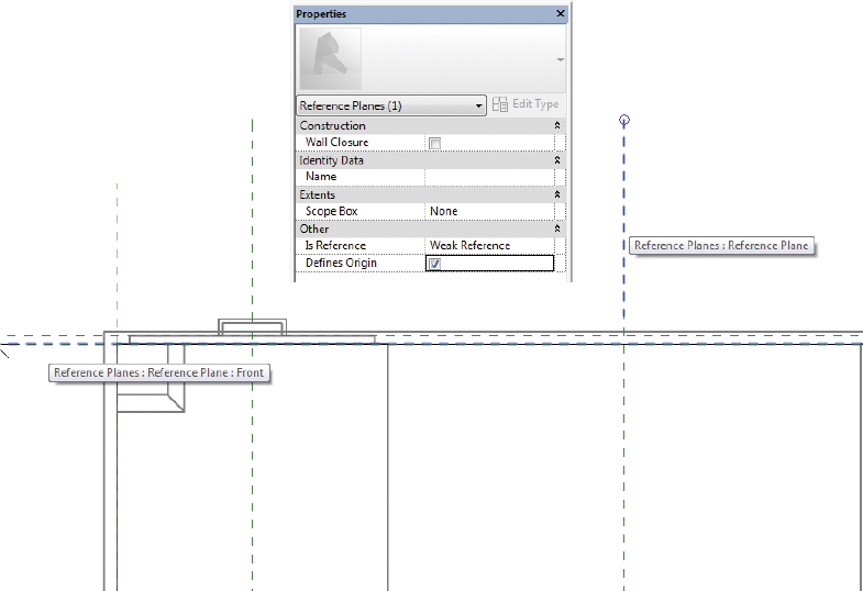
FIGURE 6.15 Editing the origin of a family
- Click Load Into Project from the ribbon to reload the family into the project, and select Overwrite The Existing Version from the Family Already Exists warning dialog that will automatically display in your view. The family initially moves to align the old insertion point with the new insertion point, effectively relocating the desk. Select the desk, and move it back relative to the chair. Afterward, if you change the type it will use the new origin and resize at the current location (Figure 6.16).
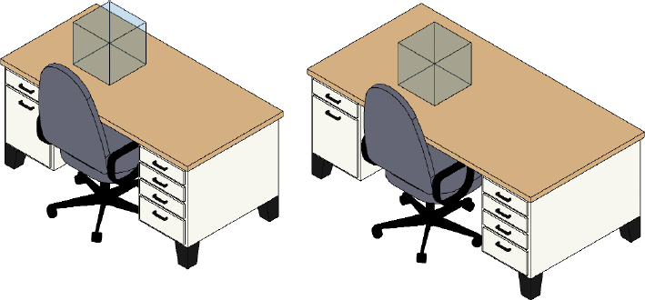
FIGURE 6.16 Different-sized desks
- The Defines Origin parameter can also be set in elevation for specific types of families, such as wall-based families. For example, this may be useful for wall cabinets where specifying an exact elevation for the top of cabinets is required.
- Select the Upper Cabinet family above the desk family, and click Edit Family in the ribbon to open the cabinets in the Family Editor.
- Open the Placement Side elevation view, and select the reference plane at the top of the cabinets. Select the check box for the Defines Origin parameter in the Properties palette as you did for the reference planes earlier (Figure 6.17). Note that the reference plane elevation is 6′-0″ (2000 mm) above the floor line.
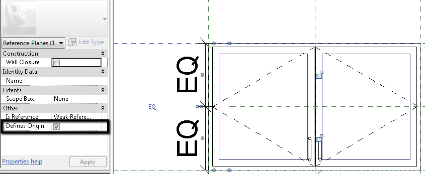
FIGURE 6.17 Reference Planes Defines Origin parameter
- Click Load Into Project from the ribbon to reload the family into the project, and select Overwrite The Existing Version as you did earlier. Notice that as with the desk, the Upper Cabinet family updates to reflect the new origin.
- From the Level 1 floor plan view, place a new instance of the overhead cabinet family on any of the walls.
- Notice that the default elevation when placing an instance in the floor plan view matches the 6′-0″ (2000 mm) elevation of the reference plane. If you select the family, there is an Elevation instance parameter in the Properties palette, which should be set to 6′-0″ (2000 mm) (Figure 6.18).
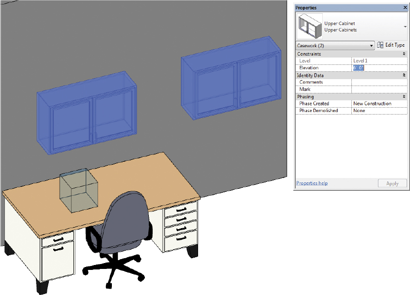
FIGURE 6.18 Elevation parameter available in project
- Changing this value will move the cabinet family in elevation relative to the reference plane you set in the Placement Side elevation view. In this example, you can enter a precise value for the top of the cabinets (Figure 6.18).
- Notice that the default elevation when placing an instance in the floor plan view matches the 6′-0″ (2000 mm) elevation of the reference plane. If you select the family, there is an Elevation instance parameter in the Properties palette, which should be set to 6′-0″ (2000 mm) (Figure 6.18).
In the following exercise you will make various changes to a generic host window that is part of the default library. A hosted family has a required relationship to a specific host category, such as Floors, Walls, Roofs, or Ceilings. Without the host, the hosted family can’t be placed.
Exercise 6.5: Modify Hosted Components
To begin, go to the book’s web page at www.sybex.com/go/revit2015essentials, download the files for Chapter 6, and open the file c06-ex-6.5start.rvt.
- From the Project Browser under Families, locate and expand the Windows category. Right-click Fixed (M_Fixed), and select Edit from the context menu to open the family in the Family Editor (Figure 6.19).
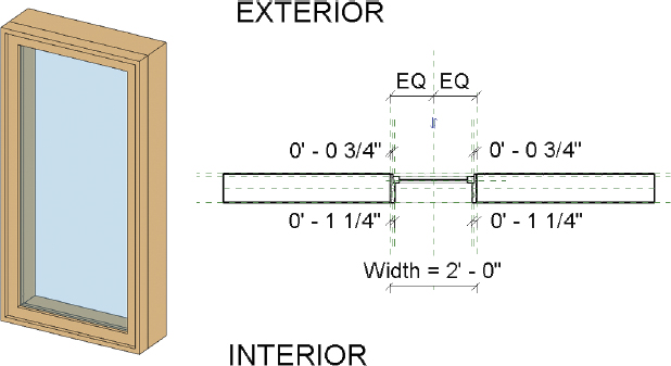
FIGURE 6.19 Window plan and 3D view in the Family Editor
- You want to keep the existing type, so begin by renaming the family via Save As.
- Press VV on the keyboard to access Visibility/Graphic Overrides (the left image in Figure 6.20). Make sure the Walls category is checked as shown and click OK. The 3D view now resembles the image on the right in Figure 6.20. Use Zoom To Fit to adjust your view.
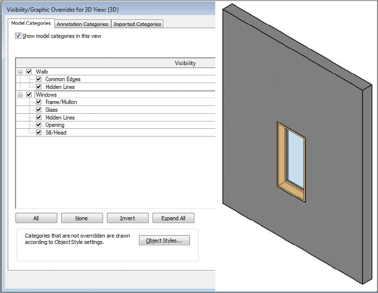
FIGURE 6.20 Visibility/Graphic Overrides for the view
- Activate the Exterior elevation view from the Project Browser window by double-clicking the Exterior elevation view (Figure 6.21).
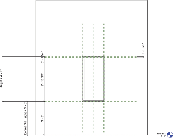
FIGURE 6.21 Reference planes and dimension parameters
- Reference planes (displayed as green dashed lines) serve as guides that allow the geometry to flex. As you can see, the window geometry has not been directly assigned to dimension parameters. Instead, the parameters are associated to the reference planes. The window geometry is then associated to the planes. This is the preferred method for constructing family geometry.
- Go to the Create tab’s Datum panel, and click the Reference Plane tool. Draw a horizontal plane around the midpoint of the window.
- Go to the Modify | Place Reference Plane tab’s Measure panel, and click the Aligned Dimension tool. Create a continuous dimension between the two outermost horizontal reference planes and the new plane you created in step 4. Click the temporary EQ icon that is active when you select the dimension just created to establish an equality constraint (Figure 6.22).
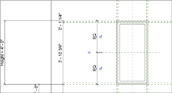
FIGURE 6.22 Adding a new reference plane and keeping it equally spaced
- Select the Frame/Mullion Extrusion, and click Edit Extrusion from the ribbon (Figure 6.23).
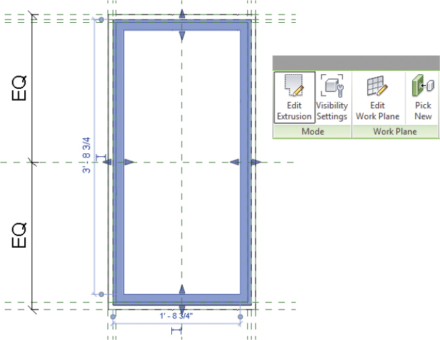
FIGURE 6.23 Frame/Mullion Extrusion
- Sketch new internal lines, as shown in Figure 6.24, to split the window into three panels. Before you finish the sketch, delete the sketch segments between the new lines (for example, by using the Split tool with the Delete Inner Segment option checked from the Options Bar). When complete, the sketch should look like the blue highlighted area in Figure 6.24.
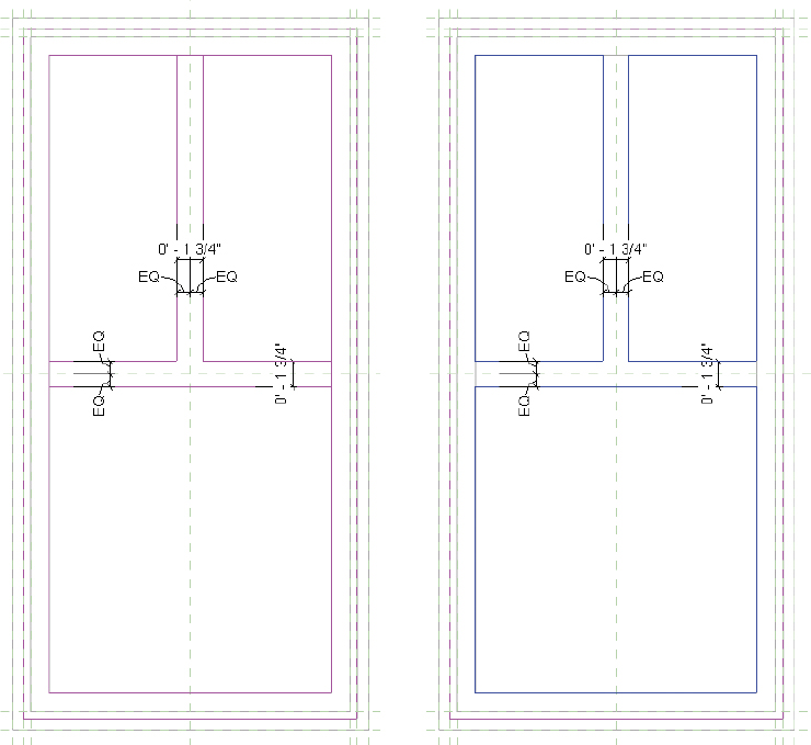
FIGURE 6.24 Edit the existing window frame.
- Click the green check button on the ribbon to finish the sketch.
- After the sketch is finished, it’s important to flex the family to make sure the different sizes will behave before you load the family into the project.
- Click the Family Types button to view all the various family types. Select a few different types from the drop-down at the top of the dialog box, and click Apply after each type is specified.
- Click OK to close the dialog box, and look at the window in 3D. The window geometry is flexing, but the window pane is still one piece of glazing.
- Select the glazing, and then click the Edit Extrusion button from the Mode panel on the contextual Modify | Frame Mullion tab. Return to the Exterior elevation, and add sketch lines aligned with your previously modified window trim, as shown in Figure 6.25. You can use the Pick Lines option in the Draw panel to make this process even easier. Remember to remove the segments of outer line using the Split tool, as you did in step 7.
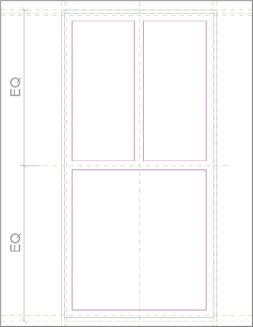
FIGURE 6.25 Modifying the window glazing
- Finish the sketch, and then repeat the previous process of testing a few different family-type parameters in order to make sure the window glazing will flex with the different sizes.
Modifying 2D Families
In addition to 3D families that contain model geometry, Revit Architecture has other categories of 2D families that consist of detail or annotation elements. These 2D families are handled differently than 3D model families. For example, tag families are treated as annotation, meaning they will resize according to the view scale. A 3D model family in Revit does not resize and is treated as physical geometry with real-world dimensions.
In the following exercises you will work with the most common types of 2D families (tags, profiles, detail components, and title blocks) to better understand their functionality and use cases: You will edit and make some changes to an existing tag family; then you will load the family back into the project.
Exercise 6.6: Edit a Tag Family
To begin, go to the book’s web page at www.sybex.com/go/revit2015essentials, download the files for Chapter 6, and open the file c06-ex-6.6start.rvt. The example file opens to the South elevation view; note the furniture tag. You will edit and modify this existing tag for your project (Figure 6.26).
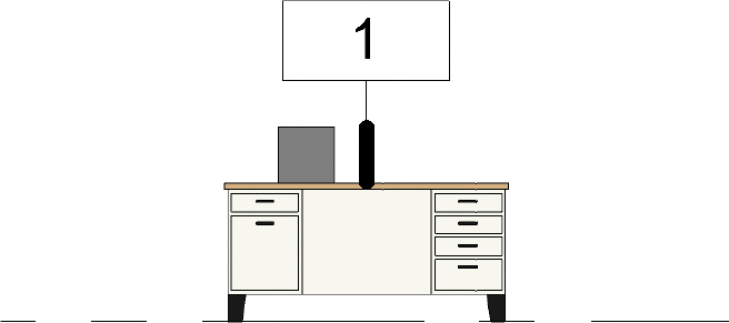
FIGURE 6.26 Existing furniture tag
- From the Project Browser under Families, expand Annotation Symbols.
- Find the Furniture Tag (M_ Furniture Tag) family, right-click it, and then select Edit from the context menu.
- In the Family Editor, click the Create tab, and activate the Line tool.
- Choose one of the arc draw tools and add lines to both sides of the tag.
- Delete the vertical lines, leaving just the horizontal lines and new arc lines (Figure 6.27). Adjust the horizontal lines if needed.
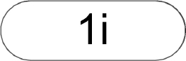
FIGURE 6.27 New furniture tag shape
- Click Load Into Project from the ribbon to reload the tag into the project and overwrite the existing tag.
- Notice that the tag instance has updated, and the finished tag should look similar to Figure 6.28. Any tags of the same type in the project will also update to reflect the changes.
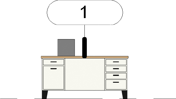
FIGURE 6.28 Completed furniture tag
- Notice that the tag instance has updated, and the finished tag should look similar to Figure 6.28. Any tags of the same type in the project will also update to reflect the changes.
In the following exercise you will edit and make changes to a profile family, which you will use to generate geometry for the railing.
Exercise 6.7: Edit a Profile Family
To begin, go to the book’s web page at www.sybex.com/go/revit2015essentials, download the files for Chapter 6, and open the file c06-ex-6.7start.rvt.
- In the Project Browser under Families, click to expand Profiles, and then right-click Rectangular Handrail (M_ Rectangular Handrail). Choose Edit from the context menu; Rectangular Handrail (M_ Rectangular Handrail) opens in the Family Editor.
- Because you want to keep your existing handrail profile intact, from the Application button choose Save As Family, and name the new profile L Shaped Handrail (M_L Shaped Handrail).
- There are some parameters that you want to maintain in this family. To make them visible, go to the Visibility/Graphic Overrides dialog box (type VV on your keyboard), and select the Annotation Categories tab. Select all the options, as shown in Figure 6.29, and click OK to close the dialog box.
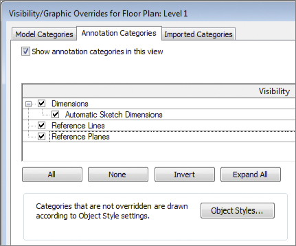
FIGURE 6.29 Adjusting the Visibility/Graphic Overrides properties of the view
- The profile view resembles the image in Figure 6.30.
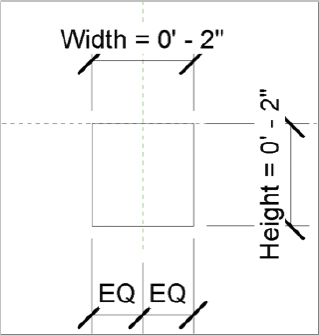
FIGURE 6.30 The profile with parameters visible
- The profile view resembles the image in Figure 6.30.
- On the Create tab in the ribbon, click the Line tool, and add new profile lines to resemble Figure 6.31. Load the profile into your project; the L Shaped Handrail profile family is now listed in your Project Browser under Families, along with the other profile families.
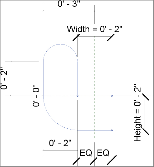
FIGURE 6.31 New handrail profile
- Next, you need to create a new railing type and associate it to your stair. In the Project Browser under Families, expand Railings Railing, and right-click Handrail - Rectangular. Select Duplicate from the context menu. The copy is named Handrail – Rectangular 2; Rename it to L Shaped Handrail (M_ L Shaped Handrail).
- Now you need to modify the properties of the railing to include the new handrail profile. To do so, right-click the L Shaped Handrail (M_ L Shaped Handrail) type you just renamed in the Project Browser, and select Type Properties, or just doubl e-click the L Shaped Handrail (M_ L Shaped Handrail) type.
- In the Type Properties dialog box, select Edit from the Rail Structure (Non-Continuous) option. Doing so opens the Edit Rails (Non-Continuous) dialog box (Figure 6.32). Click in the Profile cell to activate the list drop-down, and select the L Shaped Handrail: 2″ × 2″ profile, as shown in Figure 6.32.
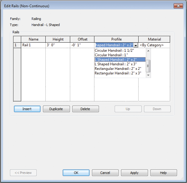
FIGURE 6.32 Editing the profile for the railing
- Click OK twice to return to the project. The new profile has been associated to the duplicate railing. All you need to do is swap out the default stair railing for the new one! Select the handrails assigned to the stair, and then choose L Shaped Handrail from the Type Selector in the Properties palette (Figure 6.33).
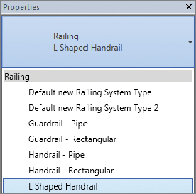
FIGURE 6.33 Selecting the new railing
In the following exercise you will edit and make changes to an existing break line family that needs to be updated for your project.
Exercise 6.8: Update Detail Components
To begin, go to the book’s web page at www.sybex.com/go/revit2015essentials, download the files for Chapter 6, and open the file c06-ex-6.8start.rvt. The example file should open to the starting view Callout of Section 1.
- In this detail callout view there is a Break Line family that you need to modify. Select the break line, and click Edit Family from the ribbon to open the family in the Family Editor.
- Select the break line in the Family Editor, and then click Edit Boundary from the ribbon.

- This element is not a line (see Figure 6.34). It’s actually a masking region (kind of like a white solid hatch) that is used to obscure geometry in your project. Some of the boundary line styles are Medium Lines, and some are Invisible Lines.
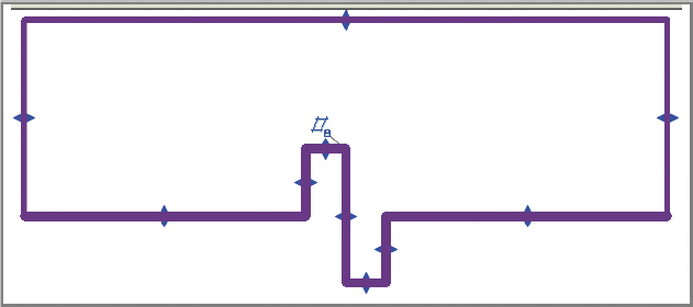
FIGURE 6.34 Selecting and editing the break line
- This element is not a line (see Figure 6.34). It’s actually a masking region (kind of like a white solid hatch) that is used to obscure geometry in your project. Some of the boundary line styles are Medium Lines, and some are Invisible Lines.
- Before you begin to modify the masking region, you should be aware of any constraints established in the family. Press VV on the keyboard. Switch to the Annotation Categories tab, and check both the Dimensions and Reference Planes options. Click OK to close the dialog box.
- In the View Control Bar, change the scale of the view to 1 1/2″ = 1′-0″ (1:10) so the dimensions are more legible. Use Zoom To Fit to see the extents of the constraints (Figure 6.35).
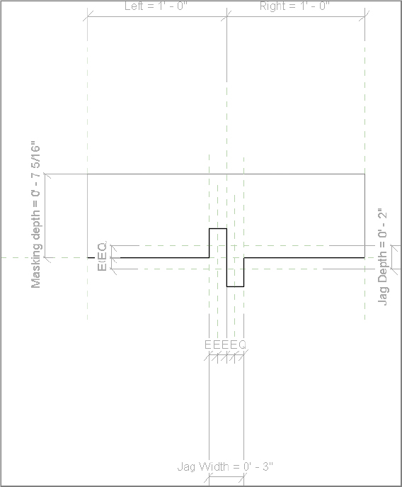
FIGURE 6.35 The masking region with all constraints displayed
- Delete the squared jag lines, as shown in Figure 6.36.
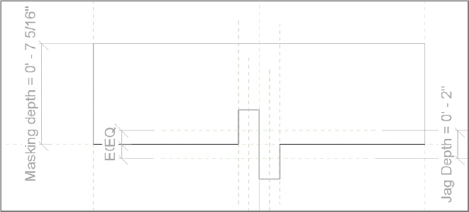
FIGURE 6.36 Delete the existing jag lines in the masking region.
- From the Create tab in the ribbon, click the Line tool, and make sure Subcategory is set to Medium Lines at the right end of the ribbon. Draw new jag lines, as shown in Figure 6.37. Make sure the lines you draw snap to the midpoints of the previous jag lines and the end points of the remaining straight lines.
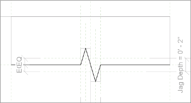
FIGURE 6.37 Sketch new jag lines in the masking region boundary.
- Click the green check button in the Mode panel of the ribbon to finish the sketch.
 Go to the Modify | Detail Items tab’s Properties panel, and click the Family Types button. Change the Jag Depth value to 0′-6″ (150 mm), as shown in Figure 6.38, and then click Apply. The size of the jag in the masking region should change. Try a few different values for Jag Depth to make sure the masking region flexes correctly. Click OK to close the dialog box.
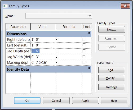
FIGURE 6.38 Change the Jag Depth value to flex the masking region.
- Click Load Into Project from the ribbon to reload the break line into your project and overwrite when prompted. Your break line will be updated in the Section Callout view to reflect the new shape.
Repeating Details
Repeating details are based on detail component families that are given rules to repeat, based on a defined spacing and rotation. As an example, elements such as brick or concrete masonry units (CMU) in a wall section are elements that repeat on a regular interval. Rather than use an array each time you need to draw these elements in a detail, the repeating detail component allows you to create persistent rules for these components. You can then draw a repeating detail with the ease of drawing a simple line.
Repeating details are located on the Annotate tab’s Component drop-down; click Repeating Detail Component. If you edit the type of any existing repeating detail component, you can create a new type using Duplicate. Then you can set the detail component you want to repeat (any that is loaded into the current project) along with the layout, spacing, and detail rotation (Figure 6.39).
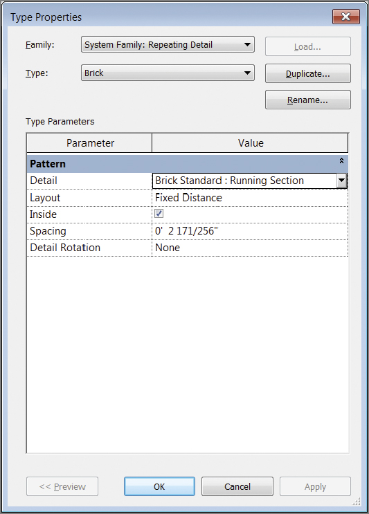
FIGURE 6.39 Repeating Detail Component type properties
Detail Specify the detail component to repeat.
Layout Specify the spacing type to use (such as Fixed Distance or Maximum Spacing).
Inside Restrict spacing to the path length.
Spacing Set the distance to space detail components.
Detail Rotation Apply detail component rotation (None, 90 Degrees Clockwise, 90 Degrees Counterclockwise, and 180 Degrees).
In the following exercise you will investigate editing other 2D annotations by modifying the default title block family. Title blocks are considered 2D families, similar to tags and detail components.
Exercise 6.9: Modify the Title Blocks
To begin, go to the book’s web page at www.sybex.com/go/revit2015essentials, download the files for Chapter 6, and open the file c06-ex-6.9start.rvt.
- Open sheet A101 from the Project Browser. Select the title block, and then choose Edit Family from the ribbon.
- You need to create a new line type for use in a grid. Go to the Manage tab’s Settings panel, and click Object Styles. When the Object Styles dialog box opens, click New under Modify Subcategories. Use the New Subcategory dialog box to create a new line called Grid Lines, as shown in Figure 6.40. From the Subcategory Of drop-down, select Title Blocks. Then click OK.

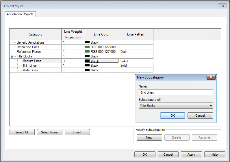
FIGURE 6.40 Adding a new subcategory
- Select the Line Color option, and modify the color to a light blue. Click OK twice to exit the Object Styles dialog box.
- You’re ready to draw the grid lines. Go to the Create tab’s Detail panel, and click the Line tool. Select the Grid Lines subcategory at the right end of the ribbon.
- Draw five vertical lines and four horizontal lines. Add a continuous dimension to each set of lines so there are two (the dimensions will not show up in the project environment). Click the EQ option, and all the lines become equally spaced (Figure 6.41).
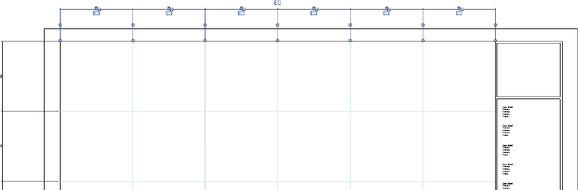
FIGURE 6.41 Adding and dimensioning grid lines
- Select all the grid lines you just created. In the Properties palette, click the Associate Family Parameter button to the right of the Visible check box to open the Associate Family Parameter dialog box.
- Click Add Parameter to open the Parameter Properties dialog box. In the Name field, type Grid Visibility. Click the Type radio button, and set Group Parameter Under to Graphics, as shown in Figure 6.42.
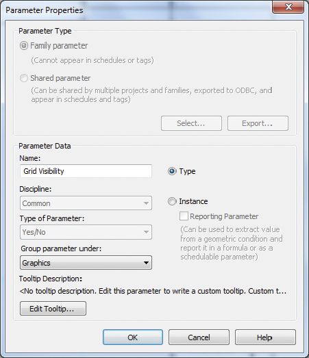
FIGURE 6.42 Creating a visibility parameter
- When you’ve finished, click OK to close both dialog boxes.
- Click Load into Project to reload the title block into your project, overwriting the parameters of the existing title block.
- Select the title block in the project, and click Edit Type in the Properties palette to open the Type Properties dialog box (Figure 6.43).
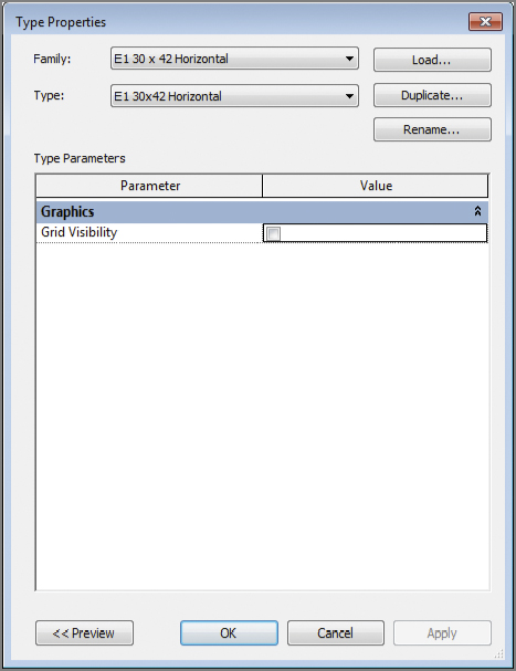
FIGURE 6.43 The Grid Visibility parameter in the Type Properties dialog box
- Deselect the parameter. When you click OK, the grid is no longer visible in the title block.
Family Tips and Best Practices
The following are some additional tips and best practices for modifying and working with families:
Name Your Reference Planes After adding new reference planes, make sure to assign them a name in the Properties palette’s Name field. This makes it much easier to keep track of each reference plane and allows them to be selected by name when you are editing the work plane.
Edit Work Planes When working in the Family Editor, you may at times need to move a work plane–based element (such as an extrusion) from one work plane to another. When selecting the element, the option to Edit Work Plane becomes available on the ribbon. You can select from a list of levels and reference planes to move the element to. This is another reason to name reference planes; if Name is blank, it will not appear under the Specify A New Work Plan ![]() Name list.
Name list.
Flex Reference Planes before Adding Geometry When creating new geometry in a family or adding a parameter to existing reference planes, be sure to properly flex the family before adding geometry. Think of reference planes as the framework for the geometry. First add reference planes, and then add dimensions between the reference planes as needed. Once the dimensions/parameters are in place, the values should be adjusted to ensure the reference planes adjust properly.
Use the Wall Closure Option For wall-hosted families (such as door and windows), reference planes can be used to determine the point where the wall layers will wrap around the family insert. You can see the difference in Figure 6.44 with Wall Closure checked and unchecked.
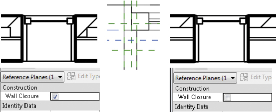
FIGURE 6.44 Wall Closure options
Deal with Filled Regions Blocking Lines in the Title Block This is a common scenario when adding filled regions and lines in a title block family.
- In the Family Editor, the filled region is added first, and the lines are added second (so the display order appears as expected with the lines on top).
- Load the title block into the project, and the filled region now overstrikes the lines. One workaround is to start a new Revit generic annotation family and cut and paste the filled regions into the generic family.
- Lastly, load the generic annotation family into the title block family and locate as needed.
Know When Objects in a Family Cannot Be Deleted Notice that when you start a new family using a default template, some of the existing elements cannot be deleted (such as some reference planes). Why is this? Any geometry that is included as part of the family template cannot be deleted when a new family is created.
Create a New Family Template By default, you cannot save an existing Revit family (.rfa) as a family template (.rft). However, you can copy the file in Windows Explorer and rename the extension from .rfa to .rft. Revit will consider this a family template afterward.
Use a “Super” Masking Region By default, masking regions mask model geometry in the project environment, but they do not mask annotation elements such as text, dimensions, tags, or detail lines. If you want to mask model and annotation elements, create a generic annotation family, and add a masking region in the family. When loaded into the project, the generic annotation family will mask both types of objects.
Use a Family Parameter Lock For parameters in a family (Family Types dialog), there is a column with an option to lock. If you lock a parameter in the family, any labeled dimension with that parameter applied will be locked. This means you will be unable to change the value in-canvas. This also means you won’t be able to dynamically flex the family in-canvas (such as dragging a reference plane with a labeled dimension attached). This is good to keep in mind if you run into odd behavior when flexing the family; make sure to first confirm whether the parameter is locked.