Chapter 8
Rooms and Color Fill Plans
In the previous chapters of this book, we discussed creating physical elements such as walls, floors, roofs, stairs, and railings; however, one of the most important elements in architecture is the spaces bounded by those physical elements. In the Autodesk® Revit® Architecture software, you have the ability to create and manage rooms as unique elements with extended data properties. Keeping room names and areas coordinated has the potential to free hours of manual effort for more productive and meaningful design-related tasks. Once rooms are tagged, you’ll be able to create coordinated color fill plans that automatically reflect any data about the rooms in your project. Any changes to the rooms are immediately reflected throughout the entire project.
In this chapter, you’ll learn to:
- Define rooms in spaces
- Add a room tag
- Modify a room boundary
- Delete a room object
- Generate color fill room plans
- Modify a color scheme
- Add tags and color fill to sections
Defining Rooms in Spaces
Rooms are unique types of objects because they do not have a clear physical representation like other model elements such as furniture and doors. Their horizontal extents are automatically determined by bounding objects in the form of walls, columns, or boundary lines that you can customize. These planar boundaries will determine the extent of the room object and thus the area of each defined room. As an additional option, you can allow Revit Architecture to calculate room volumes. The volumetric or vertical extents of rooms are determined by floors, ceilings, and roofs.
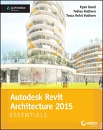
To access these calculation options, find the Room & Area panel on the Architecture tab. Click the panel title to expose the special commands, and select Area and Volume Computations (Figure 8.1).
FIGURE 8.1 Customizing Area and Volume Computations
The area and volume settings are shown at the right of Figure 8.1. In addition to setting the volume computation option, you have the ability to customize the area computation as it relates to walls. This is important to understand because it will affect the area values calculated and displayed in room tags. In this section, you will place rooms and room tags in a floor plan of a project in progress.
Room Tags
 Before you begin placing room objects, you should understand the distinction between rooms and room tags. The room is the spatial object that contains all the metadata about the space. The tag merely reports those values. In many cases, you can change the values in the room tag, and the room properties will update (and vice versa). But whereas deleting the room will delete the tag, the opposite is not true. You can delete a room tag, and the room will remain. Tags are simply 2D view–specific elements that attach to modeled objects, or, in this case, the room object.
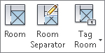
Because rooms do not represent physical objects, they have two unique properties to help you visualize and select them. One is a reference — a pair of invisible, crossing vectors that are usually near the middle of the space. You can find these by moving your mouse pointer around in a space. The reference will highlight when your mouse pointer is over one. The second unique property of a room is an interior fill. You can make these properties visible in the Visibility/Graphics settings for any view (Figure 8.2).
FIGURE 8.2 Room references and interior fill in the Visibility/Graphics settings
Room Boundaries
Rooms will automatically fill an enclosed area and will always recalculate their area when bounding objects are defined and adjusted. Elements such as walls, floors, columns, and ceilings have a Room Bounding property that lets you customize this behavior to suit your designs. You can find this property in the Properties palette when you select one of the aforementioned model elements.
Room Separation Lines
 There are times when you have a large, central open space, as in the following exercise, and you’ll need that space to be subdivided and tagged into smaller functional areas. You don’t want to add walls to carve the large space into smaller areas, especially if they don’t exist in the program; fortunately, there’s a better option. You can draw spatial dividers known as room separation lines. Room separation lines are model lines, and they show up in 3D views. The great thing about them is that they allow you to create spaces without using 3D geometry.
Deleting Rooms
While using the Room command, you can place a room and a room tag simultaneously; however, deleting a room completely from a project takes multiple steps. If you simply delete a room tag, the room object remains in the space. You can add another tag to the room object later or tag it in a different view.
If you delete a room object, the definition of the room remains in your project until you either place another room using the same definition or delete it in a room schedule. We’ll explore this behavior later with a quick exercise in which you will delete a room object, observe the unplaced room in a schedule, and then replace the room object in the floor plan.
Exercise 8.1: Add Rooms and Room Tags
From the book’s web page (www.sybex.com/go/revit2015essentials) download the project file c08-ex8.1start.rvt. Make sure the Level 1 floor plan is activated and set the scale to 1⁄4″ = 1′-0″ (1:50).
To add a room to your project, follow these steps:
- Go to the Architecture tab’s Room & Area panel, and select the Room tool.
- Hover over an enclosed space, and notice that the room boundary highlights, indicating the space in which you’re about to place a room object (Figure 8.3).
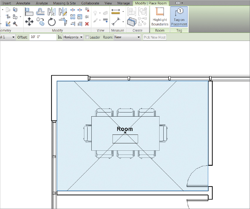
FIGURE 8.3 Adding a room and a room tag
- Click to place a room in the upper-left space on the Level 1 floor plan. Notice that the default room tag indicates only the room name and number (Figure 8.4), but more options are available.
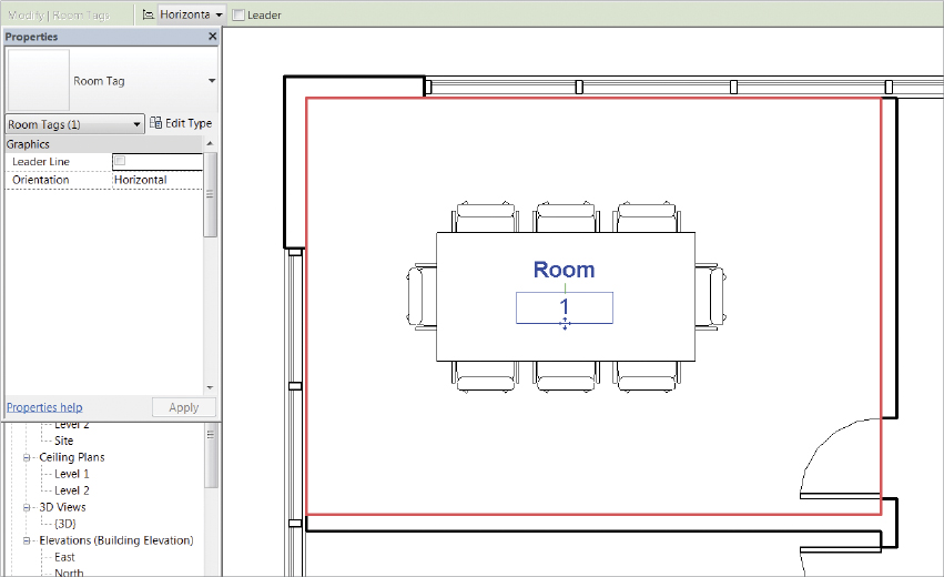
FIGURE 8.4 Room tag
- Click the Modify button or press the Esc key to exit the Room command, and then select the room tag.
- Choose the Room Tag With Area option from the Type Selector in the Properties palette. The room tag shows the area based on your project units (Figure 8.5). In this case, the room is 230 square feet (21 square meters).
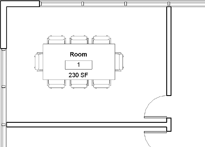
FIGURE 8.5 Room tag with area
- Select the first room you created by finding the set of invisible crossing vectors, and examine its properties in the Properties palette. You can modify the room name and number here by editing the settings under Identity Data or by directly editing the Name and Number values in the room tag. It doesn’t matter where you modify the data, because it is all stored in the room object. This makes it easy to create various plan diagrams to suit your needs.
- Change the name of the room to Small Meeting, and change the number to 101.
- Place some other rooms within the floor plan, and observe how the numbering scheme has changed.
- Select the wall at the right edge of the Small Meeting room, as shown in Figure 8.6, and move it 2′-0″ (600 mm) to the left.
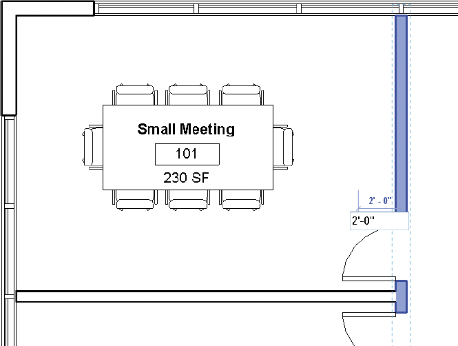
FIGURE 8.6 Moving the wall
- Notice that the moment you release the wall, the room updates with the new area information, which is immediately reported by the room tag (Figure 8.7).
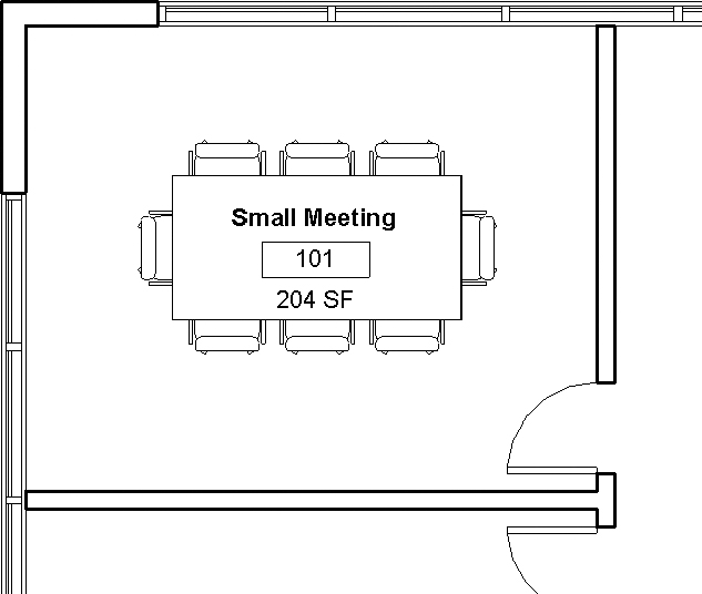
FIGURE 8.7 Updated room space and tag
- Notice that the moment you release the wall, the room updates with the new area information, which is immediately reported by the room tag (Figure 8.7).
- Continue to add rooms and tags to the Level 1 floor plan, as shown in Figure 8.8. The rooms will be numbered as you place them, so place the rooms according to the numeric sequence shown in the figure, starting with room 102.
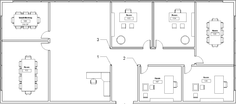
FIGURE 8.8 Adding rooms and tags
You can compare the file in its finished state on the book’s web page. Download the file titled c08-ex8.1end.rvt.
Exercise 8.2: Modify a Room Boundary
From the book’s web page (www.sybex.com/go/revit2015essentials), download the project file c08-ex8.2start.rvt. Make sure the Level 1 floor plan is activated. If you completed Exercise 8.1, you can begin the following steps where you left off.
Follow these steps to subdivide the open space in the project into three functional spaces:
- Start to add a tag to the large central open space and notice that the space will be tagged as a single room (Figure 8.9). In this exercise you want this space to be divided into smaller functional areas. Do not place a room object in this area.
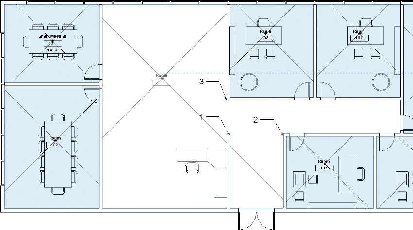
FIGURE 8.9 Tagging a large space
- Return to the Room & Area panel on the Architecture tab of the ribbon, and select Room Separator.
- Draw a line between the wall intersections labeled 1 and 2 in the sample file.
- By default, these lines are thin and black, but you can change the settings to make it easier to distinguish the lines from other elements. You will modify the Room Separator line style to be more visible in a working view, but it will be turned off in your sheet views.
- Go to the Manage tab’s Settings panel, click the Additional Settings flyout, and select Line Styles. Maximize lines to view all available line styles in the sample project.

- Change the default values for the <Room Separation> lines as follows:
- Line Weight: 5
- Color: Blue
- Line Pattern: Dot 1/32″ (Dot 1 mm)
- Click OK to finalize these changes.
- Sketch another room separator in the sample file between the wall intersections labeled 1 and 3.
- Add rooms and room tags to the subdivided open space, as shown in Figure 8.10.
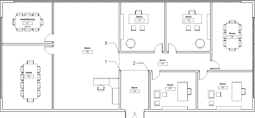
FIGURE 8.10 Adding room separation lines
Compare your completed floor plan to the example file c08-ex8.2end.rvt, available for download from the book’s web page.
Exercise 8.3: Delete a Room Object
In this exercise, we will explore what happens when you delete a room object, observe the unplaced room in a schedule, and then replace the room object in the floor plan.
From the book’s web page (www.sybex.com/go/revit2015essentials), download the project file c08-ex8.3start.rvt. If you completed Exercise 8.2, you can begin the following steps where you left off:
- From the Level 1 floor plan, delete the Small Meeting room in the upper-left corner by selecting and deleting the room object. A warning appears in the lower-right corner of the application. This warning tells you that the room you just deleted will remain in the project and can be removed or added back by deleting it from or adding it to a room schedule.
- Go to the View tab’s Create panel, click the Schedules flyout, and click Schedule/Quantities.
- Select Rooms from the Category list, and click OK.
- Add the following fields to the room schedule in this order:
- Number
- Name
- Area
- Click OK. One roo m in the schedule displays Not Placed in the Area column.
- To replace the room you just deleted, return to the Level 1 floor plan, and start the Room command again. This time, open the Room drop-down on the Options Bar. You see any unplaced rooms available in your project (Figure 8.11).
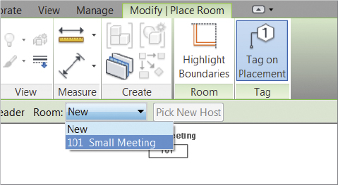
FIGURE 8.11 Place rooms with unplaced room definitions.
- Select the unplaced room from the list, and place the room back in the floor plan.
- Return to the schedule you created by locating the Schedules/Quantities category in the Project Browser and opening the Room Schedule.
- Highlight the name field for the first unnamed room object, and modify the value to read Large Meeting. Practice renaming all the remaining rooms, either in the schedule or in the floor plan, as shown in Figure 8.12, naming the spaces appropriate to their function.
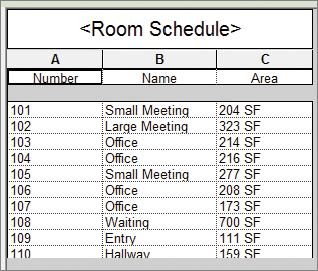
FIGURE 8.12 Renaming rooms in a room schedule
![]() Compare your completed exercise to the example file
Compare your completed exercise to the example file c08-ex8.3end.rvt, available for download from the book’s web page.
Generating Color Fill Room Plans
Creating color fill plans in Revit Architecture is easier to accomplish than most other design applications. Because color fills are associated with the elements of your building design, they will constantly update as existing information is modified or new information is added. This allows you to focus on communicating rather than coordinating your design information — as if resolving your design isn’t already hard enough!
In the following exercises, we will explore how to add a color scheme to your floor plan and section and how to modify the values. By default, solid fill colors will be automatically assigned to each unique value in a color scheme. Fortunately, you can completely customize the colors and fill patterns for the scheme.
Exercise 8.4: Add and Modify a Color Scheme
From the book’s web page (www.sybex.com/go/revit2015essentials), download the project file c08-ex8.4start.rvt.
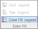
- Go to the Annotate tab’s Color Fill panel, and select the Color Fill Legend tool.
- Click anywhere in the whitespace of the drawing area, and a dialog opens that allows you to select the space type and color scheme (Figure 8.13).
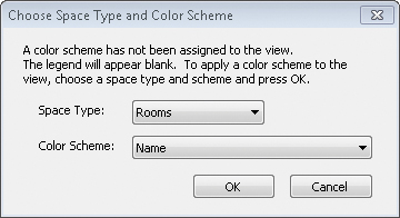
FIGURE 8.13 Defining the color fill legend
- Set Space Type to Rooms and Color Scheme to Name. Click OK.
 To edit the color assignments, select the color fill legend in the plan view. You can then select the Edit Scheme tool from the contextual ribbon. You can also access the same settings in the Properties palette for the current view. Just find the Color Scheme property, and click the button in the parameter field.
- Select the Edit Scheme tool, which opens the Edit Color Scheme dialog where all the values are available for editing (Figure 8.14).
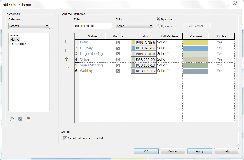
FIGURE 8.14 Edit Color Scheme dialog
- With the Edit Color Scheme dialog box open, select the Color field in the row for Small Meeting. The Color dialog box opens.
- Modify the color values to Red 203, Green 242, and Blue 222. When you complete the changes, the fill color automatically updates to reflect your changes (Figure 8.15). Notice that all rooms that share the same name also share the same color fill. Color fills were automatically created based on assigned room names. If a room is renamed, the color fill should change accordingly.
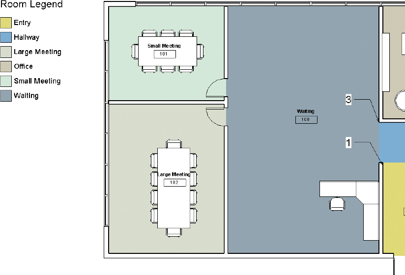
FIGURE 8.15 Resulting color fill
- Continue modifying the color values in your color scheme until you are satisfied with its appearance (Figure 8.16).
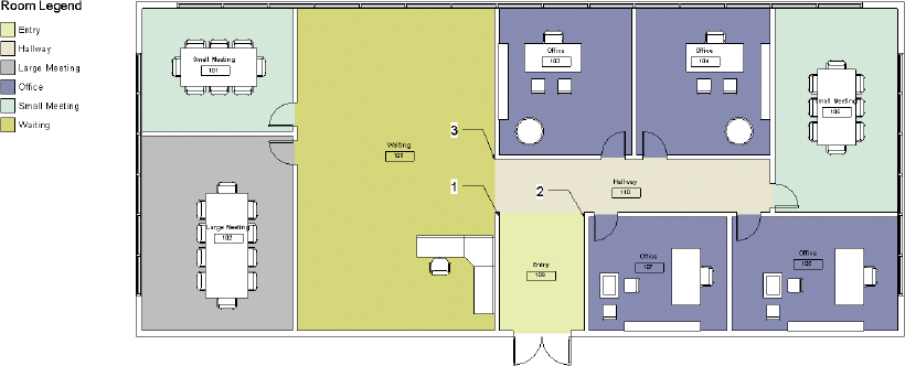
FIGURE 8.16 Updated color fill
Compare your completed floor plan to the example file c08-ex8.4end.rvt, available for download from the book’s web page.
Exercise 8.5: Add Tags and Color Fills in Section
Room tags and color fills are not just for use in floor plans — they can be utilized in sections as well. Let’s examine this functionality with a quick exercise. From the book’s web page (www.sybex.com/go/revit2015essentials), download the project file c08-ex8.5start.rvt. If you completed Exercise 8.4, you can begin the following steps where you left off:
- Activate the Level 1 floor plan. Go to the View tab’s Create panel, and select the Section tool.
- Create a section across the project plan view, as shown in Figure 8.17.
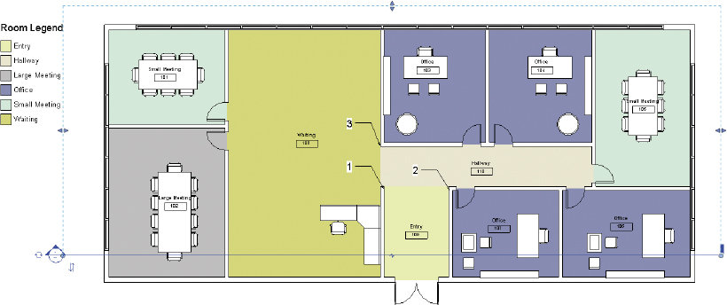
FIGURE 8.17 Creating the building section
- Press the Esc key to deselect the section you just created. Double-click the section head to open the new view. Figure 8.18 illustrates the new building section. Although all the geometry is shown correctly, it would certainly help to tag the spaces with their room names.
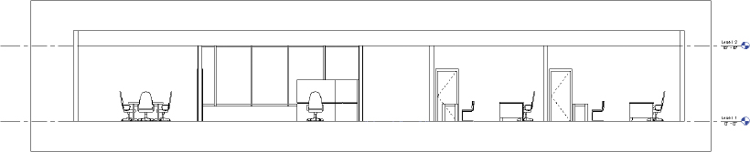
FIGURE 8.18 Resulting building section
 Select the Tag All tool on the Annotate tab’s Tag panel. Doing so opens the Tag All Not Tagged dialog, allowing you to tag numerous element categories in a view simultaneously. You need to tag only rooms in this exercise, so select the Room Tags category, as shown in Figure 8.19, and then click OK.
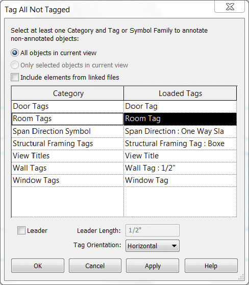
FIGURE 8.19 Adding room tags with the Tag All Not Tagged tool
- To move a tag that may be overlapping element geometry, click the Modify button in the ribbon (or press the Esc key), select a tag, and drag it using the grip that appears near the selected tag (Figure 8.20). You can also grab and drag a tag directly without selecting it first.
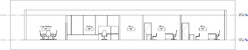
FIGURE 8.20 Room tags shown in section
- Return to the Annotate tab’s Color Fill panel, select the Color Fill Legend tool, and place the legend in the section view.
- Once again, set Space Type to Rooms and Color Scheme to Name, and click OK. The rooms are filled with the same pattern and color in the section view as the color fill in the plan view, as shown in Figure 8.21.
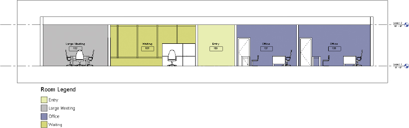
FIGURE 8.21 Room colors in the section view match the plan colors.
- Notice in Figure 8.21 that the color fill is obscured by some of the model elements such as doors and furniture. This is because the color fill can be placed as a background or foreground in any view. Find the Color Scheme Location parameter in the Properties palette for the settings of the current view. Change this setting to Foreground, and observe how the color fill display is modified.
Compare your completed section to the example file c08-ex8.5end.rvt, available for download from the book’s web page.