Chapter 11
Details and Annotations
So far, you have used the Autodesk® Revit® Architecture software to create walls, doors, roofs, and floors; to define space; and to bring your architectural ideas into three-dimensional form. In each of these cases, the geometry is typically modeled based on a design intent, meaning that your goal hasn’t been to model everything but rather to model enough to demonstrate what the building will look like. To this end, it becomes necessary to embellish parts of the model or specific views with detailed information to help clarify what you’ve drawn. This embellishment takes the shape of 2D detail elements in Revit Architecture that you will use to augment views and add extra information.
In this chapter, you will learn to:
- Create a detail
- Enhance a detail with 2D elements
- Create a repeating detail component
- Annotate a detail
- Create a legend
Creating Details
Even when you’re creating details, Revit Architecture provides a variety of parametric tools that allow you to take advantage of working in building information modeling (BIM). You can use these tools to create strictly 2D geometry or to augment details created from 3D plans, sections, or callouts. To become truly efficient at using Revit Architecture to create the drawings necessary to both design and document your project, you must become acquainted with these tools.
These view-based tools are located on the Detail panel of the Annotate tab (Figure 11.1). This small but very potent toolbox is what you will need to familiarize yourself with in order to create a majority of the 2D linework and components that will become the details in your project. To better understand how these tools are used, let’s quickly step through some of them. You’re going to use the Detail Line, Region, Component, and Detail Group tools, because they will make up your most widely used toolkit for creating 2D details in Revit Architecture.
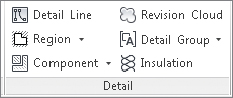
FIGURE 11.1 The Detail panel of the Annotate tab
Detail Line
![]() The Detail Line tool is the first tool located on the Detail panel of the Annotate tab. This tool is the closest thing you’ll find to traditional drafting in the Revit Architecture software. It lets you create view-specific linework using different lineweights and tones, draw different line shapes, and use many of the same manipulation commands you would find in a CAD program, such as offset, copy, move, and so on.
The Detail Line tool is the first tool located on the Detail panel of the Annotate tab. This tool is the closest thing you’ll find to traditional drafting in the Revit Architecture software. It lets you create view-specific linework using different lineweights and tones, draw different line shapes, and use many of the same manipulation commands you would find in a CAD program, such as offset, copy, move, and so on.
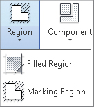
Using the Detail Line tool is fairly easy. Selecting the tool changes your ribbon tab to look like Figure 11.2. This tab has several panels that allow you to add and manipulate linework.
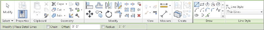
FIGURE 11.2 The Detail Line toolset
This tab primarily contains three panels: Modify, Draw, and Line Style. You’ve seen the Modify panel before. It contains the host of tools you’ve used so far for walls, doors, and other elements. Here you can copy, offset, move, and perform other tasks. The Draw panel lets you create new content and define shapes, and the Line Style drop-down allows you to choose the line style you’d like to use.
Region
 The next tool on the Detail panel of the Annotate tab is the Region tool. Regions are areas of any shape or size that you can fill with a pattern. This pattern (much like a hatch in AutoCAD) dynamically resizes with the region boundary. Regions layer just like detail lines do and can be placed on top of, or behind, other 2D linework and components. Regions also have opacity and can be completely opaque (covering what they are placed on) or transparent (letting elements show through).
![]() There are two types of regions: filled regions and masking regions.
There are two types of regions: filled regions and masking regions.
Filled Regions Filled regions allow you to choose from a variety of hatch patterns to fill the region. They are commonly used in details to show things such as rigid insulation, concrete, plywood, and other material types defined by a specific pattern.
Masking Regions Masking regions, on the other hand, come in only one flavor. They are white boxes with or without discernible border lines. Masking regions are typically used to hide, or mask, from a view certain content that you don’t want shown or printed.
Component
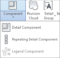 The Component drop-down menu lets you insert a wide array of component types into your model. These are 2D detail components, or collections of detail components in the case of a repeating detail. Detail components are schedulable, taggable, keynotable 2D families that allow an additional level of standardization in your model.
Detail components are 2D families that can be made into parametric content. In other words, a full range of shapes can be available in a single detail component. Because they are families, they can also be stored in your office library and shared easily across projects.
To add a detail component to your drawing, follow these steps:
- Select Detail Component from the Component drop-down list located on the Annotate tab.
- Use the Type Selector to choose from detail components that are already inserted into the model.
If you don’t see a detail component you want to insert in the Type Selector, try this:
- Click the Load Family button on the Modify | Place Detail Component tab.
- Insert one from the default library or your office library.
Arranging Elements in the View
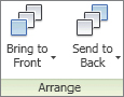 Knowing how to change arrangement is an important part of detailing so you don’t have to draw everything in exact sequence. Arrangement allows you to change the position of an element, such as a line or a detail component, relative to another element. Much like layers in Adobe Photoshop or arrangement in Microsoft PowerPoint, Revit Architecture allows you to place some elements visually in front of or behind others. Once an element or group of elements is selected and the Modify menu appears, on the far right you’ll see the Arrange panel.
From here, you can choose among four options of arrangement:
- Bring to Front
- Bring Forward
- Send to Back
- Send Backward
Bring Forward and Send Backward are available selections using the drop-down arrows next to Bring to Front and Send to Back, respectively. Using these tools will help you get your layers in the proper order.
 Repeating Detail Component
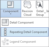 Repeating elements are common in architectural projects. Masonry, metal decking, and wall studs are some common elements that repeat at a regular interval. The Revit Architecture tool you use to create and manage these types of elements is called the repeating detail component, and it’s located in the Component flyout on the Annotate tab.
This tool lets you place a detail component in a linear configuration in which the detail component repeats at a set interval; you draw a line that then becomes your repeating component. The default Revit Architecture repeating detail is common brick repeating in section. Creating elements like this not only lets you later tag and keynote the materials but also allows you some easy flexibility over arraying these elements manually.
Before you create a repeating detail component, let’s examine one such component’s properties. Select Repeating Detail Component and choose Edit Type from the Properties palette to open the Type Properties dialog box shown in Figure 11.3.
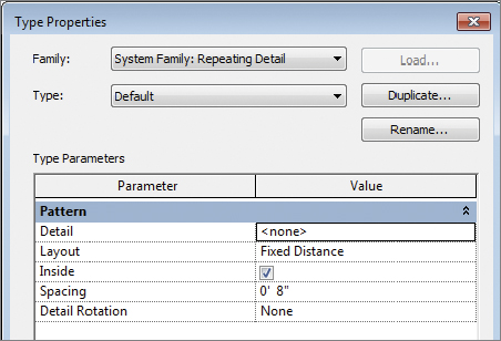
FIGURE 11.3 Type Properties dialog box for a repeating detail
Here’s a brief description of what each of these settings does:
Detail This setting lets you select the detail component to be repeated.
Layout This option offers four modes:
- Fixed Distance This represents the path drawn between the start and end points when the repeating detail is the length at which your component repeats at a distance of the value set for Spacing.
- Fixed Number This mode sets the number of times a component repeats itself in the space between the start and end points (the length of the path).
- Fill Available Space Regardless of the value you choose for Spacing, the detail component is repeated on the path using its actual width as the Spacing value.
- Maximum Spacing The detail component is repeated using the set spacing, and the number of repeated components is set so that only complete components are drawn. Revit Architecture creates as many copies of the component as will fit on the path.
Inside This option adjusts the start point and end point of the detail components that make up the repeating detail. Deselecting this option puts only full components between start and end points rather than partial components. As an example, if you have a run of brick, selecting the Inside check box will make a partial brick at the end of the run. If you want to see only full bricks (none that would be cut), deselect the option.
- Spacing This option is active only when Fixed Distance or Maximum Spacing is selected as the method of repetition. It represents the distance at which you want the repeating detail component to repeat. It doesn’t have to be the actual width of the detail component.
- Detail Rotation This option allows you to rotate the detail component in the repeating detail.
Insulation
 The best way to think of the Insulation tool is as a premade repeating detail. You’ll find this tool on the Detail panel of the Annotate tab.
Selecting this tool allows you to draw a line of batt insulation, much like a repeating detail. You can modify the width of the inserted insulation from the Options Bar (Figure 11.4). The insulation is inserted using the centerline of the line of batt, and you can shorten, lengthen, or modify the width either before or after inserting it into your view.

FIGURE 11.4 Modifying the Insulation width in the Options Bar
Detail Groups
Detail groups are similar to blocks in AutoCAD and are a quick alternative to creating detail component families. Like modeled groups, these are a collection of graphics though contain detail lines, detail components, or any collection of 2D elements. While you will probably want to use a detail component to create something like blocking, if you plan to have the same blocking and flashing conditions in multiple locations, you can then group the flashing and blocking together and quickly replicate these pieces in other details. Like blocks in AutoCAD, manipulating one of the detail groups changes all of them consistently throughout the model.
There are two ways to make a detail group. Probably the most common is to create the detail elements you’d like to group and then select all of them. When you do, the Modify context tab appears:
 Click the Create Group button under the Create panel to make the group.
- When you’re prompted for a group name, name the group something clear like Window Head Flashing or Office Layout 1 rather than accepting the default name Revit Architecture wants to give it (Group 1, Group 2, and so on).
The other way to create a detail group is as follows:
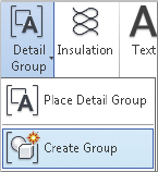
- Go to the Annotate tab’s Detail Group flyout and click the Create Group button. You are prompted for the type of group (Model or Detail) as well as a group name.
- Model Model groups contain model elements (elements that are visible in more than one view). Choose Model if you want elements to be visible in more than one view or if they are 3D geometry.
- Detail Detail groups contain 2D detail elements and are visible only within the view you’re in (you can copy or use them in other views). Choose Detail if you’re creating a group containing detail lines or other annotations and 2D elements.
- When you select the elements, you’re taken into Edit Group mode. A yellow transparency is overlaid on top of the view, and elements in the view appear gray.
- To add elements to the group, click Add and then choose your selected items (Figure 11.5).
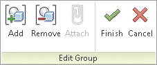
FIGURE 11.5 The Edit Group panel
- You can also remove unwanted elements.
- When you’ve finished, click the green Finish check mark, and your group will be complete.
You can place any group you’ve already made using the Place Detail Group button on the Annotate tab’s Detail Group flyout. Groups insert like families, and you can choose the group you’d like to insert from the Type Selector on the Properties palette.
Linework
 Although not part of the Annotate tab, the Linework tool is an important feature in creating good lineweights for your details. Revit Architecture does a lot to help manage your views and lineweights automatically, but it doesn’t cover all the requirements all the time. Sometimes the default Revit Architecture lines are heavier or thinner than you desire for your details. This is where the Linework tool comes in handy; it allows you to modify existing lines in a view-specific context.
To use the Linework tool, follow these steps:
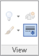
- Go to the Modify tab’s View panel and click the Linework button, or use the keyboard shortcut LW.
- You will see the familiar Line Style Type Selector panel on the right of the tab.
- Select a line style from the list.
- Simply choose the style you want a particular line to look like; then select that line in the view.
The lines you pick can be almost anything: cut lines of model elements, families, components, and so on. Selecting the line or boundary of an element changes the line style from whatever it was to whatever you have chosen from the Type Selector. Figure 11.6 shows a before and after of the sill detail with the linework touched up.
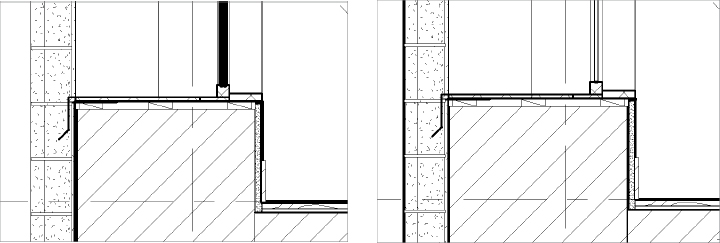
FIGURE 11.6 Before and after the Linework tool
You can also choose to visually remove lines using this tool. Doing so leaves the line in the view or as a part of the 3D element but makes it effectively invisible for the sake of the view. Do this by selecting the <Invisible Lines> line type. This is a good alternative to covering unwanted linework with a masking region.
Exercise 11.1: Enhance a Detail with Regions
Enhancing your model with 2D linework and components is an efficient way to add more information to specific views without modeling everything. It is not necessary to model flashing, blocking, or other elements shown only in large-scale format detail drawings. Using detail lines, regions, and detail components, you can enhance your views to show additional design intent.
From the book’s web page (www.sybex.com/go/revit2015essentials), download the c11-ex11.1start.rvt file and open the view Exterior Detl, Typ, which you’ll find in the Sections (Building Section) node of the Project Browser. In the following exercise, you will create a detail and enhance the detail using filled and masking regions to accurately represent built conditions within a typical window detail:
- Use the Callout tool on the View tab to create a new detail of the second-floor window sill: Create a new callout, and name it Exterior Window Sill, Typ. The starting view looks like Figure 11.7.
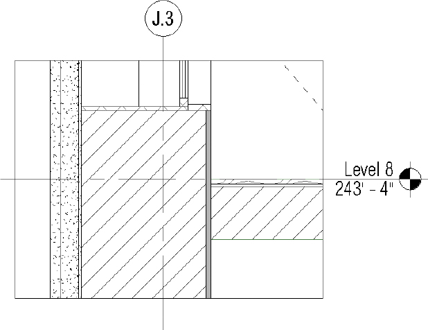
FIGURE 11.7 The window sill detail before embellishment
- Click the Filled Region button under the Region flyout on the Annotate tab. Choose <Invisible lines> from the Line Style drop-down on the Modify tab, and create a box bounding the floor slab (Figure 11.8).
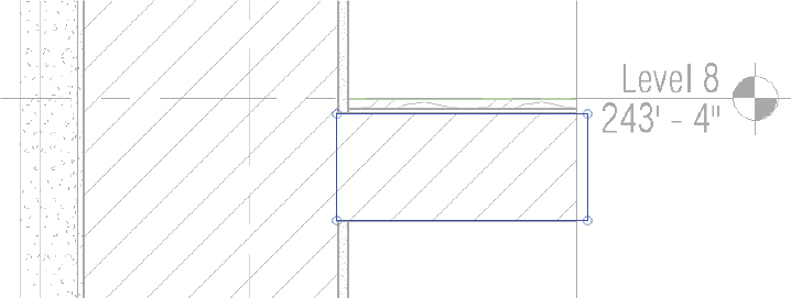
FIGURE 11.8 Modifying the boundary of the filled region
- Select the top and bottom edges of the bounding box, which should align with the cut planes of the floor, and use the Line Style drop-down to change the lineweight to Medium Lines.
- Click the Edit Type button in the Properties palette to open the Type Properties dialog box. Because there is no defined region type that is identical to existing materials, you need to make one. Click Duplicate, name the new region type 00 Existing, and click OK.
- Check to make sure these settings are in the Properties palette:
- Fill Pattern: Set this field to Drafting, and choose ANSI31.
- Background: Set this to Opaque.
- Line Weight: Set this to 1.
- Color: Set this to Black
- Click OK when you’ve finished.
- Click the green check mark
 to complete the sketch. Your finished filled region appears highlighted and slightly transparent.
 - Click off the region to see the finished product. The invisible line on the left doesn’t cover the cut of the wall, and a thinner line remains.
- Highlight the filled region again and use the Nudge tool (the arrow keys on the keyboard) to move the region over slightly to cover the remainder of the finished wall. The finished region looks like Figure 11.9.
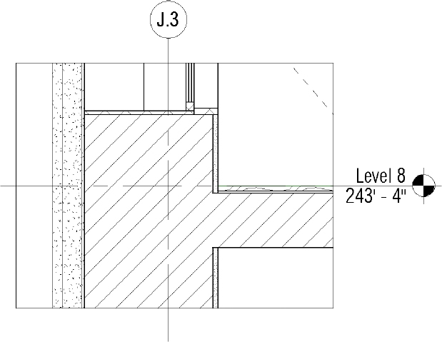
FIGURE 11.9 The finished filled region
- Choose the Masking Region tool from the Region flyout on the Annotate tab.
- With Line Style set to Thin Lines, create a box 1″ (25 mm) deep under the window sill, creating a blank space where you will later add some other 2D components, such as blocking. (Figure 11.10).
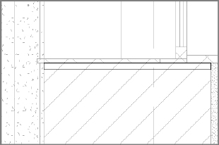
FIGURE 11.10 Adding a masking region
- Click the green check to complete the sketch. The finished sill looks like Figure 11.11.
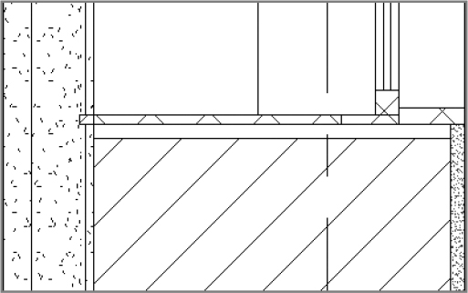
FIGURE 11.11 The completed sketch
Upon completion, your detail should resemble the c11-ex11.1end.rvt file, available in the download for this chapter. Save this detail; you’ll return to it again in the next exercise.
Exercise 11.2: Add Detail Components and Detail Lines
The next step is to add some detail components for blocking and trim. From the Chapter 11 downloadable files, open the c11-ex11.2start.rvt file, or continue with your opened file if you’ve completed the previous exercise. Choose Application ![]() New
New ![]() Family, and choose
Family, and choose Detail Item.rft. When you’re creating detail components, as with any other family, you’ll start with two reference planes crossing in the center of the family. This crossing point is the default insertion point of the family.
The first family, Blocking, is straightforward. You’ll use Masking Region instead of the Lines tool so you have a clean, white box that you can use to layer over and mask other elements you might not want to see.
- Select the Masking Region tool on the Create tab, and draw a box with the lower-left corner at the origin. The box should be 1″ (25 mm) high and 3″ (75 mm) wide.
- Click the green check mark to complete the region.
- On the Create tab, click the Line tool, and draw a line diagonally across the box to denote blocking. The family should look like Figure 11.12.
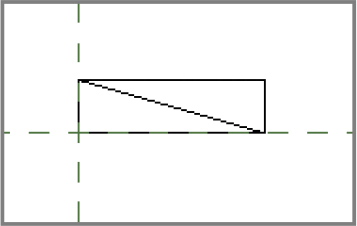
FIGURE 11.12 Creating a blocking detail component
- Choose Application
 Save As Family, and name the family 06 Blocking. Place it in a folder with the model.
 - Click the Load Into Project button at the far right on the ribbon to add the family to the model.
- If you have more than one project open, make sure you choose either your continued exercise file or the example file for this exercise,
c11-ex11.2start.rvt.
- If you have more than one project open, make sure you choose either your continued exercise file or the example file for this exercise,
- To add the blocking detail component to your view, return to the Exterior Window Sill, Typ. detail, and click the Detail Component button from the Component flyout button on the Annotate tab.
- Insert pieces of blocking at the left, right, and center of the sill (Figure 11.13).
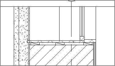
FIGURE 11.13 Inserting and placing the blocking
- Create a new detail item using steps 1–3 for another detail component representing the baseboard (do not create a diagonal line to denote blocking), and use the dimensions 1″ (25 mm) wide by 6″ (150 mm) high.
- Name the new family 06 Baseboard.
- Save the baseboard, and click Load Into Project, selecting the accurate project file if more than one file is open.
- Navigate to the view Exterior Window Sill, Typ. if it’s not already open, and place the baseboard at the corner of the gypsum board and finished floor. The detail looks like Figure 11.14.
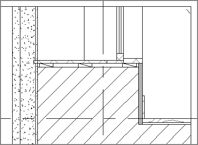
FIGURE 11.14 The sill detail with base
- Sometimes, it is easier and more effective to simply use detail lines to create the necessary features in a detail. For these purposes, you want to create some flashing at the window sill.
- Choose the Detail Line tool, and select Medium Lines from the Line Style drop-down menu.
- Using the Detail Line tool, draw in some flashing for the window sill (Figure 11.15).
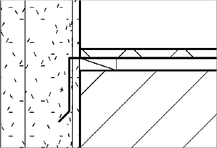
FIGURE 11.15 Adding flashing using detail lines
Compare your finished detail with the c11-ex11.2end.rvt file, available in the download from the book’s web page. You’ll return to this detail again for the next exercise.
Exercise 11.3: Create a Repeating Detail Component
In the following exercise, you will create a custom repeating detail for the sill detail you’ve been working on. The exterior of the building is terracotta brick and will have visible joint work every 8″ (200 mm). From the Chapter 11 downloadable files, open the c11-ex11.3start.rvt file, or continue with your opened file if you’ve completed the previous exercise. Follow these steps:
- Select a new Detail Component family again. Choose Application New Family, and choose
Detail Item.rftfrom the list. - Create a masonry joint 6″ (150 mm) long and 3⁄8″ (10 mm) high with a strike on one of the short ends (Figure 11.16) using a filled region with no hatch pattern.
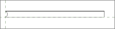
FIGURE 11.16 The grout detail component
- Save the family as 04 Grout, and load it into the project, selecting the correct open project file if more than one file is open.
- Click the Esc button to clear the active command. Back in the project file, go to the Annotate tab’s Detail panel, open the Component flyout, and choose the Repeating Detail Component tool.
- Choose Edit Type from the Properties palette, and then click the Duplicate button in the Type Properties dialog.
- Name the new type 04 Terracotta Grout, and click OK.
- Change the properties of this new type to reflect the detail component you just created and its spacing. Change only the following fields:
- Detail: Set this field to 04 Grout, the family you just created.
- Spacing: Set this value to 8″ (200 mm).
- The Type Properties dialog box looks like Figure 11.17. Click OK when you’ve finished.
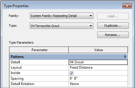
FIGURE 11.17 The repeating detail’s type properties
- With the Repeating Detail command still active, draw a line all the way up the left edge of the exterior wall, starting at the base of the view, placing the new joint over the terracotta exterior.
- Place one of the joints directly below the window sill, by using the Nudge tool to shift the detail into the right location. This appears on top of the flashing you drew earlier, so you’ll want to move the flashing to the front.
- Select the flashing detail line, and choose Bring To Front from the Arrange panel. The completed detail looks like Figure 11.18.
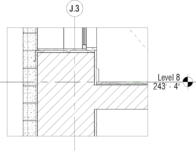
FIGURE 11.18 The finished window sill detail
Although this detail needs annotations before you can think about placing it onto a sheet, you can begin to see how you have used the 3D geometry of the model and were able to quickly add embellishment to it in order to create a working project detail. Compare your finished detail with the c11-ex11.3end.rvt file, available in the download from the book’s web page. You’ll return to this detail again for the next exercise.
Annotating Your Details
![]() Notes are a critical part of communicating design and construction intent to o wners and builders. No drawing set is complete without descriptions of materials and notes about the design. Now that you’ve created a detail, you need to add the final touches of annotations to communicate size, location, and materiality. The tools you will use for annotations are found on the same Annotate tab that you used to create details. These are the Dimension, Text, and Tag panels shown in Figure 11.19.
Notes are a critical part of communicating design and construction intent to o wners and builders. No drawing set is complete without descriptions of materials and notes about the design. Now that you’ve created a detail, you need to add the final touches of annotations to communicate size, location, and materiality. The tools you will use for annotations are found on the same Annotate tab that you used to create details. These are the Dimension, Text, and Tag panels shown in Figure 11.19.

FIGURE 11.19 The Revit Architecture annotation tools
Dimensions
The Dimension panel is the first panel located on the Annotate tab. Revit Architecture provides you with a variety of options for dimensioning the distance between two objects, including Aligned, Linear, Angular, Radial, Diameter, and Arc Length dimensioning tools. The dimension tool you will use the most often is Aligned, located on the left side of the Dimension panel shown in Figure 11.19. It can also be found on the Quick Access toolbar ![]() . Using the Aligned dimension tool is quite simple. Click once on the first reference object to start the dimension string, and click again on the second reference object to finish the dimension.
. Using the Aligned dimension tool is quite simple. Click once on the first reference object to start the dimension string, and click again on the second reference object to finish the dimension.
Tags
Tags are 2D view-specific elements that attach to modeled or detail elements to report information based on that element’s type or instance properties. Any modeled or detail element can be tagged; however, they are most commonly used to identify your basic building blocks—doors, windows, wall types, and rooms. You can add tags to your project by navigating to the Tag panel located on the Annotate tab. When you select the Tag by Category tool and then select an object in your model, Revit Architecture will automatically assign the correct tag type to the associated material. From there, you can enter the appropriate information within the tag object.
Text
Not all elements in Revit Architecture have materiality to them, and sometimes tags are not the best way to convey information. In these cases, you can use text. The Text tool is located on the Text panel of the Annotate tab.
When you’re using text in your model, it’s important to remember that text is not linked to any element or material; it’s 2D view-specific information. If you label something with text or use text to call out notes, the text doesn’t dynamically update as elements change in the model.
Exercise 11.4: Add Dimensions to Your Detail
In your detail, you have added aspects to the window family to reflect some of the details needed for construction. Now, with much of the linework and elements in the view, you need to annotate and add dimensions. From the Chapter 11 downloadable files, open the c11-ex11.4start.rvt file, or continue with your opened file if you’ve completed the previous exercise.
- Select the Aligned dimension tool, and place a dimension string from the grid line to the centerline of the wall, as shown in Figure 11.20.
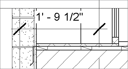
FIGURE 11.20 Adding a dimension string
- Click Esc to clear the active command. Highlight the dimension string, and you see two sets of blue dots on either side. One set controls the length of the witness line (the line that extends from the actual element you dimensioned to the tick mark), and the other (on top of the tick mark) controls the witness line’s location.
- To place the dimension string in the accurate location, select the blue dot that controls the witness line location, and drag it to the exterior of the wall. The dimension automatically updates.
- Add another dimension string from the grid line to the back of the window jamb.
- To relocate the text, grab the blue dot under the text and drag the text string to the right. Once the dimension text is outside the dimension string, Revit Architecture adds an arc associating the text to the dimension (Figure 11.21).
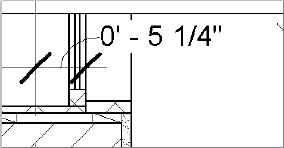
FIGURE 11.21 Modifying the text location
- Add another dimension that locates the gypsum board relative to the grid line (Figure 11.22). By default, the exterior face of the gypsum board won’t highlight to accept the dimension. With your mouse hovering over the right edge of the gypsum board, press the Tab key, and you can place the other side of the dimension string.
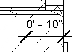
FIGURE 11.22 Dimensioning the wall location
- To change the dimension text to eliminate the white masking region behind the text, highlight the dimension by left-clicking it, and select Edit Type from the Properties palette. The Type Properties dialog box for dimensions opens, as shown in Figure 11.23.
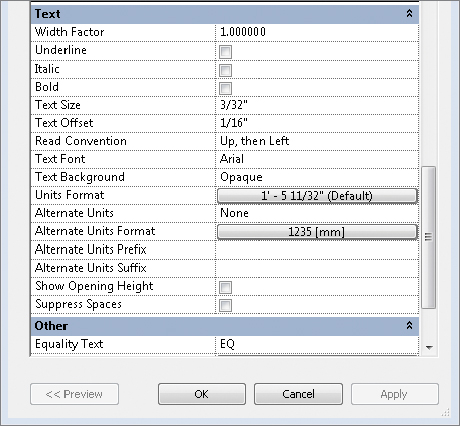
FIGURE 11.23 Dimension type properties
- Scroll to the bottom to find the Opaque value next to the Text Background option. This controls that white box behind the dimension. Set it to Transparent, and click OK. The dimension now has a transparent background.
- Add a dimension locating the window sill relative to the floor, as shown in Figure 11.24.
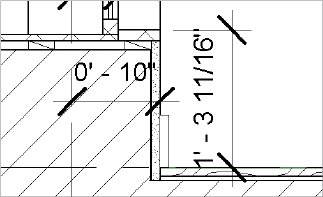
FIGURE 11.24 Dimensioning the window sill
- To change the dimension string from the awkward length shown to a more reasonable value, you need to change the location of one of the two objects you’ve dimensioned. The floor probably isn’t going to move, but you can reposition the window slightly. Select the window. The dimension string turns blue, and the numbers become very small (Figure 11.25).
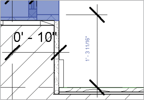
FIGURE 11.25 To change the dimension string value, change the location of the objects dimensioned by selecting the window.
- Select the blue text, and type 1′ 4″ (400 mm) in the text box (Figure 11.26). Press Enter. The window pushes up just a bit and resets the dimension string.
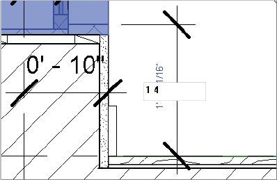
FIGURE 11.26 Entering a value into a dimension string
With all the dimensions on the detail, it should look like Figure 11.27. Compare your finished detail with the c11-ex11.4end.rvt file, available in the download from the book’s web page. You’ll return to this detail again for the next exercise.
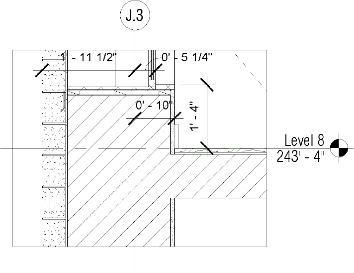
FIGURE 11.27 The dimensioned detail
Exercise 11.5: Add Tags and Text to Your Detail
From the Chapter 11 downloadable files, open the c11-ex11.5start.rvt file, or continue with your opened file if you’ve completed the previous exercise.
Now that you have embellished and dimensioned the detail, it’s time to add some annotations in the form of tags and text. In this exercise, you’ll tag the window as well as some of the materials in the detail to help identify these items to the contractor. Also, the shims you placed as part of the window family do not have a way to tag a material and need to be called out using text. Follow these steps:
- Choose the Tag by Category button on the Annotate tab’s Tag panel, and select the window.

- Revit Architecture displays the warning shown in Figure 11.28. It tells you that Revit Architecture has added a tag, but that it has fallen outside of your view. By default, Revit Architecture places tags in the center of the element being tagged. In this case, the tag resides in the middle of the window cut in section, which is above your crop box.

FIGURE 11.28 The tag fell outside of the crop window.
- Revit Architecture displays the warning shown in Figure 11.28. It tells you that Revit Architecture has added a tag, but that it has fallen outside of your view. By default, Revit Architecture places tags in the center of the element being tagged. In this case, the tag resides in the middle of the window cut in section, which is above your crop box.
- Click Esc to clear the active command. Select the box that defines the crop region for the detail. Doing so highlights the crop box and also an invisible, dashed box called the annotation crop box.
- Drag the upper limit of the annotation box higher, and you will eventually see the Window tag you placed on the window (Figure 11.29).
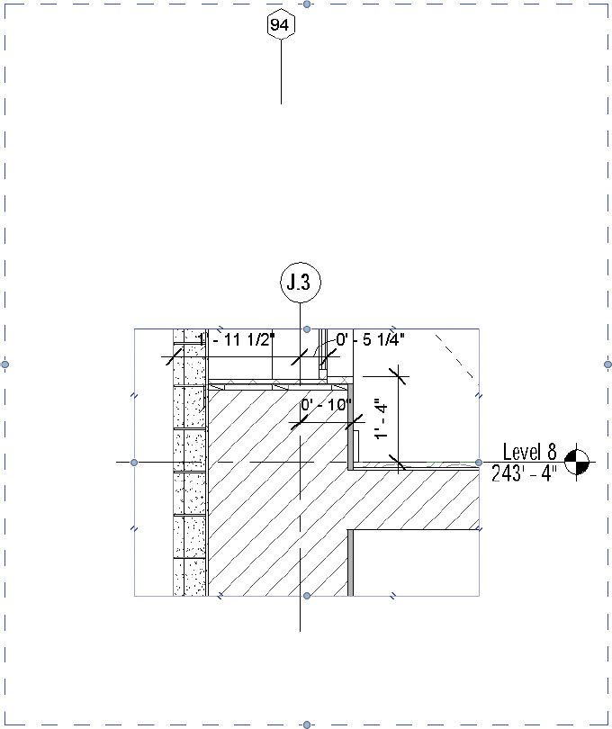
FIGURE 11.29 Extending the annotation crop window
- Highlight the tag, and in the Options Bar deselect the Leader check box that is shown checked (Figure 11.30). Doing so lets you drag the tag down—leader free—and place it in the crop region.

FIGURE 11.30 Removing the leader from the Window tag
- Choose the Material Tag button from the Tag panel on the Annotate tab. With the tag selected, mouse over the vertical panel shown in Figure 11.31. The material there has been prepopulated with 5/8″ GYPSUM BOARD as a tag through the material (from the Manage tab). Select the material, and place the tag.
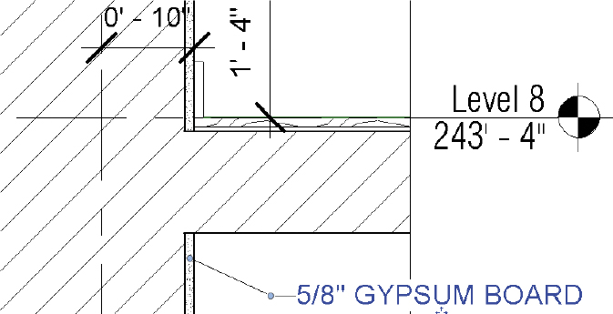
FIGURE 11.31 Using the Material tag
- Notice that by default the tag has no arrowhead. Select the tag, and choose Edit Type from the Properties palette. Here in the tag’s Type Properties dialog, you can assign an arrowhead. Choose 30 Degree Arrow for the Leader Arrowhead property, and click OK (Figure 11.32).
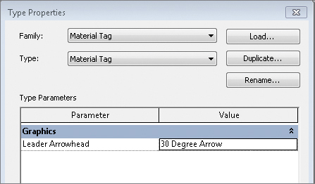
FIGURE 11.32 Adding an arrowhead to the tag
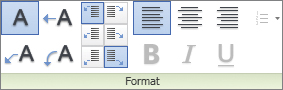 Choose the Text command on the Annotate tab. Doing so opens the Modify Text tab. The tools on the Format panel control the leaders, leader location, justification, and font formats, respectively.
- For now, leave the selections at the defaults, choose a location on the screen, and click the left mouse button. Doing so begins a text box. Type 1/2″ (Figure 11.33). Click the mouse to finish the text and hit Esc to clear the active command.
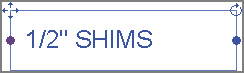
FIGURE 11.33 Adding text to the detail
- Select the text you just created. To add a leader, click the Add Leader button at the upper left of the Format panel
 .
. - Move the text and leader into position with the other notes. In this way, you can complete the annotations on the detail (Figure 11.34) and begin the next one.
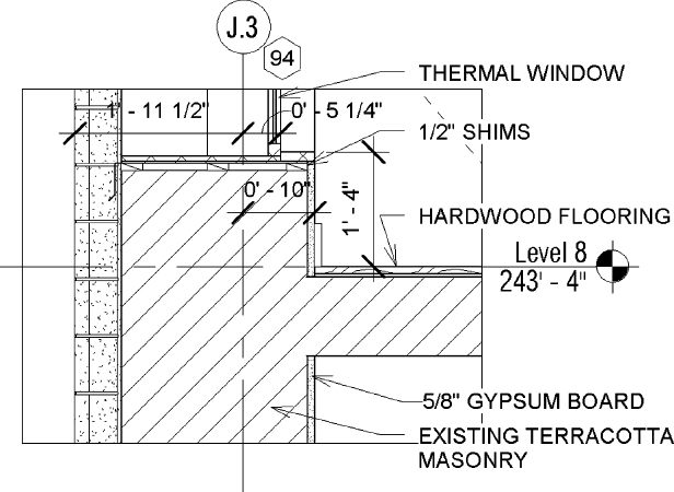
FIGURE 11.34 Finishing the detail
Compare your finished detail with the c11-ex11.5end.rvt file, available in the download from the book’s web page.
Creating Legends
![]() Legends are unique views in Revit Architecture because you can place them on more than one sheet, which is not typical for most view types. These can be great tools for things such as general notes, key plans, or any other view type you want to be consistent across several sheets. It’s important to note that anything you place inside a legend view—doors, walls, windows, and so on—will not appear or be counted in any schedules. Legend elements live outside of any quantities present in the model.
Legends are unique views in Revit Architecture because you can place them on more than one sheet, which is not typical for most view types. These can be great tools for things such as general notes, key plans, or any other view type you want to be consistent across several sheets. It’s important to note that anything you place inside a legend view—doors, walls, windows, and so on—will not appear or be counted in any schedules. Legend elements live outside of any quantities present in the model.
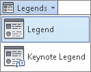 The Legend tool is located on the View tab. You can create two types of legends from this menu: a legend, which is a graphic display, or a keynote legend, which is a text-based schedule. Both legend types can be placed on multiple sheets, but for the following exercise, you’ll focus on the legend.
The simplest type of legend would include notes such as general plan or demolition comments that would appear in each of your floor plans. More complex legends include modeled elements, such as walls.
You can add modeled elements to the legend view by expanding the Families tree in the Project Browser and navigating to the chosen family. Once a modeled element is added to a legend, you’ll notice three sections on the Modify | Legend Components settings in the Options Bar. This menu is consistent for any of the family types you insert.
Family This drop-down menu allows you to select different family types and operates just like the Type Selector does for other elements in the model.
View The View option lets you change the type of view from Plan to Section.
Host Length This option changes the overall length (or, in the case of sections, height) of the element selected.
As part of the sample workflow, you may want to present some of the wall types as part of your presentation package to demonstrate the Sound Transmission Class (STC) of the walls and the overall wall assembly. Because these wall types will appear on all the sheets where you use them in the plan, you’ll make them using a legend.
Exercise 11.6: Create a Legend
From the Chapter 11 downloadable files, open the c11-ex11.6start.rvt file, or continue with your opened file if you’ve completed the previous exercise.
- Choose the Legend button on the View tab’s Legends flyout. Creating a new legend is much like creating a new drafting view.
- A New Legend View dialog box opens (Figure 11.35), where you can name the legend and set the scale.
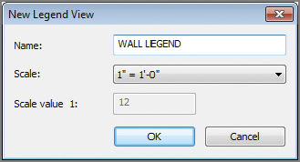
FIGURE 11.35 Creating a legend
- A New Legend View dialog box opens (Figure 11.35), where you can name the legend and set the scale.
- Name this legend WALL LEGEND, and choose 1″ = 1′-0″ (1:10) for the scale. Click OK to create the legend.
- To add wall types or any other family to the legend view, expand the Families tree in the Project Browser and navigate to the Walls family. Expand this node, and then expand the Basic Wall node.
- Select the Interior – Gyp 4 7/8″ wall type, and drag it into the legend view.
- Change the view’s detail level in the view’s Properties palette from Coarse to Medium or Fine so you can see the detail in the wall.
- Remember, you can turn off the thicker lines in the view by clicking the Thin Lines button
 in the Quick Access Toolbar (QAT).
- Remember, you can turn off the thicker lines in the view by clicking the Thin Lines button
- Highlight the inserted wall, and look at the Modify | Legend Components settings in the Options Bar (Figure 11.36).

FIGURE 11.36 Select a legend component to access its properties in the Options Bar.
- Change View to Section, and change Host Length to 1′-6″ (500 mm).
- The wall now looks like a sectional element. By adding some simple text and detail components, you can embellish the wall type to better explain the elements you’re viewing (Figure 11.37).
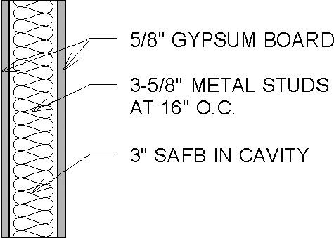
FIGURE 11.37 Add other annotations and detail components to embellish the wall-type section.
- The wall now looks like a sectional element. By adding some simple text and detail components, you can embellish the wall type to better explain the elements you’re viewing (Figure 11.37).
- Continue the exercise by adding the Exterior – Brick wall type to the legend along with some additional text notes.
Compare your finished legend with the c11-ex11.6end.rvt file, available in the files you downloaded from the book’s web page.