Chapter 14
Repeating Objects, Best Practices, and Quick Tips
This chapter provides an overview of different methods for repeating objects in the Autodesk® Revit® Architecture software. We will also discuss tips, optimizations, and best practices to help keep your project files running smoothly.
In this chapter, you’ll learn to:
- Use repeating objects
- Optimize performance
- Utilize best practices
- Use quick tips and shortcuts
- Locate additional resources
Repeating Objects
Revit Architecture offers several approaches to repeat geometry throughout your project. Some are better suited for specific conditions depending on your project, so we’ll provide an overview for each, along with key takeaways.
 Component Families As outlined in Chapters 5 and 6, component families are best described as anything manufactured away from the job site and used throughout your project files. Component families are the core type of repeating object you will utilize. They can be constructed to be parametric by containing multiple types of the same family; think of one door with 10 types to represent variations in standard sizes. Component families can also be used with (and are a critical aspect of) groups, links, and assemblies.
The following are the key takeaways:
- Component families can contain types. Instead of creating separate door families, you can create one, and you can create multiple types within the family. Each type can be configured with parameters to flex the geometry to match specific sizes or visibility requirements.
- Component families can be saved outside the project as stand-alone RFA files and loaded back in or into other projects. This allows for the creation of shared libraries so the entire office or multiple offices can utilize the same components.
- Component families can be 2D or 3D. If a component family simply needs to be quantified or scheduled but isn’t visible outside plan orientation views, it could initially be created as 2D geometry. Later if the project needs changing, the family can always be modified.
 Groups Groups are collections of project objects such as system families, component families, or detail items. Model groups are collections of 3D geometries, whereas detail groups are strictly 2D. Groups are easily created by selecting the objects you want to include in the group and choosing Create Group on the ribbon. Creating a group will generate a single element that contains a collection of objects (which also makes it easy to move everything together). A good use case for groups is a condominium or apartment project. For typical units or apartments that will appear more than once in the project, you can select the objects and create a group. This group can then be copied or inserted at multiple project locations. Edit one group type, and all instances will update to match.
The following are the key takeaways:
- A group instance can automatically be converted to a link at any time by selecting the group and choosing Link on the contextual ribbon panel.
- Groups can be saved out of a project as stand-alone project files (right-click the group type in the Project Browser and choose Save Group).
- Group members can be excluded from a group instance. This is extremely powerful for groups that may have one or two variations (but otherwise are identical). Instead of creating a new group type, Tab+select the group member you want to exclude from the group instance, and click the Exclude symbol that appears near the element. Should you need the member back, Tab+select the group again, and click the Restore Excluded Group Member symbol.
- A wall in the project can still join with a wall inside a group.
 Assemblies Assemblies are similar in many aspects to groups but with some unique tools directed toward construction workflows. Assemblies are collections of project objects similar to groups, organized in the Project Browser, along with any associated assembly views. To create an assembly, select the objects you want to include in the view, and choose Create Assembly on the ribbon.
The following are the key takeaways:
- Revit automatically detects whether changes to an assembly make it unique and, if so, creates a new assembly type.
- Assemblies have an exclusive tool called Assembly Views. These views are organized in the Project Browser (under the assembly) and create isolated views of the specific assembly type only. To create assembly views, select an assembly, and click Create Views on the ribbon.
- Assemblies do not allow as many object categories to be added as groups do. There are restrictions on some object categories (they cannot be added to the assembly) such as other assembled objects, annotation/detail items, groups, imports, links, model lines, masses, rooms, images, curtain systems, stacked walls, or curtain walls.
 Revit Links Revit project files can be linked into one another. This is useful not only to divide large projects or campus buildings but also to repeat geometry. For example, your project may have identical wings or buildings on campus. The Revit project can be linked in and even allows for copies of the link to be created (all instances will update if reloaded). Links also have project-wide controls under Manage Links. Here you can reload, unload, or entirely remove the link from the host project.
The following are the key takeaways:
- A link can be bound into the project (which will place all geometry into a new group). Simply select the link instance and choose Bind Link on the ribbon.
- A link can be copied, mirrored, rotated, or further modified. There can also be multiple instances of the same link.
- Under Visibility/Graphic Overrides, there is a Revit Links tab. Changing the display settings between By Host View and By Linked View allows the link to follow the settings of the host view or use the appearance settings of the link view.
- A wall in the host project cannot join with a wall in the link.
Optimize Performance
You can optimize your hardware in a number of ways to get the most out of your configuration. You should first look at the minimum hardware specifications for a computer running Revit Architecture. Autodesk has published those requirements on its website, and they are updated with each new release of the application. You can find the current specs at www.autodesk.com/revit; choose Features and then System Requirements under the Autodesk Revit Products page. Beyond the default specifications, you can do a number of things to help keep your files nimble. This section contains some additional recommendations.
Figuring Out How Much RAM Your Project Will Need
You can use a rough formula to figure out how much memory you’re actually going to need for your project. The OS and other applications such as Microsoft Outlook will use some of your RAM, but you can predict how much RAM Revit Architecture will need to work effectively. The formula is as follows:
Let’s look at a couple of examples to demonstrate how this works. You have a project file with no linked files, and the file size on your server is 250 MB. So, 250 × 20 = 5,000 MB, or roughly 5 GB of RAM to operate.
In another example, you have a 300 MB file, a 100 MB structural model linked in, and four CAD files at 5 MB each.
(300 × 20) + (100 × 20) + (20 × 20) = 8,400 MB, or roughly 8.4 GB of RAM. For this example specifying at least 10–12 GB of RAM for the workstation would be recommended.
The one area where it can be difficult to predict, since each project file varies, is when upgrading a project. Upgrading a project is usually the most memory-intensive operation in Revit. Since it is a one-time operation (for each release), you can dedicate one workstation for this task. Specify one workstation with additional memory for upgrading, if you find it necessary.
Reducing File Size
The next area to improve model performance is to reduce your file size so you’re not using as much RAM. Here are some tips to do that and thereby improve your file speed:
 Close your views. Close windows you’re not using to help minimize the drain on your resources. It’s easy to lose track of how many views are open, even if you’re concentrating on only a few views—and the more you open, the more information you will load into active RAM. If your main view is maximized, you can use the Close Hidden Windows tool to close all the windows but your active one; on the View tab, click the Close Hidden Windows button (it’s also conveniently located in the Quick Access toolbar). You can also assign this command to a keyboard shortcut such as XX.
Delete or remove unused CAD files. While working on a project you will often want to load content from another source to be used as a background. This could be a client’s CAD as-built drawings or a consultant’s mechanical, electrical, and plumbing (MEP) design. You might link or import these files into your drawing and forget about them during the busy course of the project. As you’ve seen from the earlier tips on RAM use, all these small files add up. Getting rid of them can speed up your file and is good housekeeping. If the file is linked, you can remove it using the Manage Links button from the Insert or Manage tab. Note that the Unload button does not remove it from the Revit Architecture project. If it is inserted, right-click an instance of the CAD file, and choose Select All Instances from the context menu. Clicking Delete will then remove all the instances in the view or project depending on your Select All Instances choice.
Link instead of importing CAD files. As a general rule, always link a CAD file rather than import it. You generally have greater control using a link than using imported geometry. The link can be removed or unloaded from the project and all views with a single action. A CAD link is similar to an Xref in Autodesk® AutoCAD® software and will update if the original CAD file is modified. An imported CAD file may be spread across several different views and is more difficult to hide or remove from specific views or the entire project. It also has no association to the original CAD file and will not subsequently update if modified outside the Revit project.
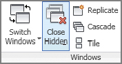
Turn on volume computation only as needed. Calculating the volumes on a large file can slow down your model speed immensely, especially when modifying bounding elements such as walls. Volume calculations are typically turned on when exporting to gbXML, but sometimes teams forget to turn them back off again. Volumes will recalculate each time you edit a room, move a wall, or change any of the building geometry. Turn off this option using the Area And Volume Computations dialog box found below the Room & Area panel on the Architecture tab (Figure 14.1).
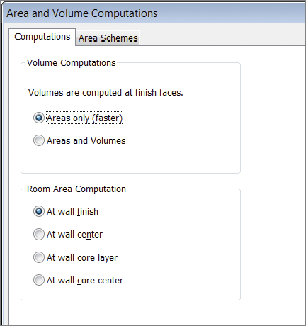
FIGURE 14.1 Choose the Areas Only setting to minimize unneeded computations.
Utilize Best Practices
Good file maintenance is critical to keeping your files running smoothly and your file sizes small. Here are some best practices and workflows identified in other areas of the book but consolidated in this section as a quick reference:
- Manage the amount of information shown in views. An overload of information in views not only will make them look cluttered but also will adversely affect project performance. Show only what you need to show in a view. Do this by minimizing the level of detail, view detail, view depth, and view content. Here are some simple tips to keep your individual views working smoothly:
- Minimize the level of detail. Set your detail level, found in the View Control Bar, relative to your drawing scale. For example, if you’re working on a 1⁄8″ = 1′-0″ (1:100) plan, you probably don’t need Detail Level set to Fine. Doing so will cause the view to have a higher level of detail than the printed sheet can show, and you’ll end up with black blobs on your sheets and views that are slow to open and print.
- Minimize view depth. View depth and crop regions are great tools to enhance performance. As an example, a typical building section is shown in Figure 14.2. The default behavior causes a regeneration of all the model geometry to the full depth of that view every time you open the view. To reduce the amount of geometry that needs to be redrawn, drag the section’s far clip plane (the blue dashed line when you highlight the section) in close to the cutting plane. You can also enter a more precise value in the Properties palette with the Far Clip Offset parameter.
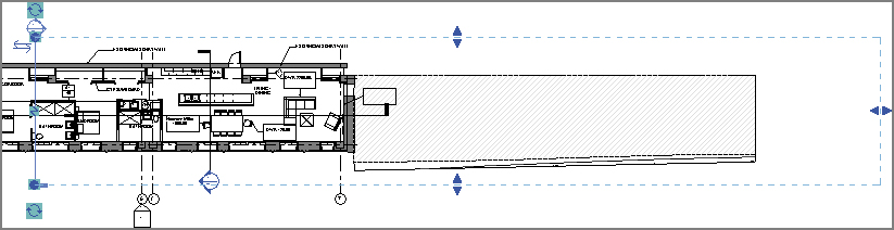
FIGURE 14.2 Minimizing the view depth
- Minimize view content. Another best practice is to limit the amount of visible content to only what is necessary in a view. For example, in an exterior 3D view of an entire building, perhaps you can turn off categories for interior content under Visibility/Graphic Overrides (such as electrical fixtures, plumbing fixtures, and furniture).
Model only what you need. Although it is possible to model to a very small level of detail, don’t fall into the trap of over-modeling. Be smart about what you choose to model and how much detail you show. If it’s not conveying information about the project, maybe it’s not needed. The amount of information you do or do not model should be based on your project size and complexity, your time frame, and your comfort level with the software.
When trying to decide how much detail to put into a model or even a family, you can use the following three very good rules of thumb to help you make the right decision for the element you’re looking to create:
- Scale At what scale will this detail be seen? If it’s a very small-scale detail, it might be simpler to just draw it in 2D in a drafting view.
- Repetition How many times will the element appear in the drawing set? If it will appear in only one location or only one time, it might be easier to draft it in 2D rather than try to model the element. If it will appear in several locations, modeling is probably the better solution. The more exposure an element has in the model (the more views it shows in), the more reason you have to model it. For example, doors are good to model; they show in elevations and plans all over the sheet set.
- Quality How good at modeling families in Revit Architecture are you, honestly? Don’t bite off more than you can chew. If you’re new to Revit Architecture, keep it simple and use 2D components. The more projects you complete, the better you’ll understand the BIM workflow.
Watch out for imported geometry. Although you have the ability to use geometry from several other file sources, use caution when doing so. Remember that everything you link into your model takes up about 20 times the file size in your system’s RAM. So, linking a 60 MB NURBS-based ceiling design will equal 1.2 GB of RAM and more than likely slow down your model. Deleting unused CAD files, using linking rather than importing, and cleaning up the CAD geometry before insertion will help keep problems to a minimum.
Utilize Purge Unused. You won’t use every family and every group you create in your model. The Purge Unused tool lets you get rid of those unused elements to help keep your file sizes at a reasonable level. This too can be found on the Manage tab on the Settings panel. If a file is very large, the tool can take several minutes to run, but eventually you’ll be presented with a list (Figure 14.3) of all the unused elements in your file.
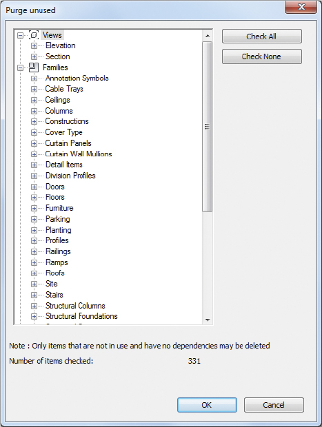
FIGURE 14.3 Use the Purge Unused dialog box to reduce file size.
Use Quick Tips and Shortcuts
In addition to all the things you can do to hone your Revit Architecture skills, you will begin to learn tips and shortcuts as your experience grows using the software. Here are some good tips to get you started:
Filter your selection. You can filter selection behavior by customizing any combination of links, underlay elements, pinned elements, the ability to select elements by face, and the ability to drag elements on selection. For example, on a large project, you may want to disable link selection to prevent accidental selection of linked models. These options can be toggled on the fly and are available in two locations: under the Modify arrow and on the lower-right corner of the status bar (Figure 14.4).
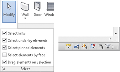
FIGURE 14.4 Selection filters
Customize your double-click behavior. If you navigate to Application ![]() Options
Options ![]() User Interface
User Interface ![]() Double-Click Options, you can customize the action for the element types (Figure 14.5). The available actions will vary based on the element type; however, each type has a Do Nothing option. For example, if you find yourself accidentally double-clicking to edit families, you can change the default behavior.
Double-Click Options, you can customize the action for the element types (Figure 14.5). The available actions will vary based on the element type; however, each type has a Do Nothing option. For example, if you find yourself accidentally double-clicking to edit families, you can change the default behavior.
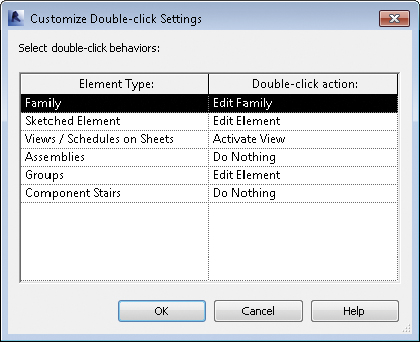
FIGURE 14.5 Double-click settings
Make elevators visible in your plans. Suppose you want to create a shaft that will penetrate all the floors of your building and put an elevator in it that will show in all your plans. You could do this with an elevator family and cut a series of holes in the floors by editing floor profiles, but sometimes those holes stop aligning on their own recognizance. Fortunately, you can do both things at once using the Shaft tool on the Opening panel of the Architecture tab. Here, not only can you cut a vertical hole through multiple floors as a single object, but also you can insert 2D linework (using the Symbolic Line tool when editing the shaft opening sketch) to represent the elevator in plan view (Figure 14.6). Every time the shaft is cut, you’re certain to see the elevator linework.
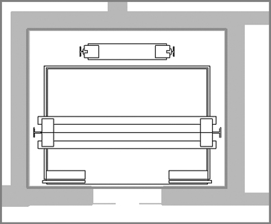
FIGURE 14.6 Adding elevators to a shaft
Orient to view. Creating perspective views of isolated design elements can be quick and easy in plan view or in section view, but let’s say you want to see that same element in 3D to be able to work out the details.
- Create a callout or section cut isolating the area in question. If you’re using a section, make sure to set your view depth to something practical.
- Open the default 3D view or any other 3D orthographic view of the project.
- Right-click the ViewCube, select Orient To View, and select the callout or section from the context menu.
- Your 3D view looks identical to your section or plan region, but by rotating the view, you can see that portion in 3D.
Customize your shortcuts. To edit your keyboard shortcuts, choose Application ![]() Options. Choose the User Interface tab, and then click the Customize button. You can also access this command on the View tab in the ribbon under the User Interface flyout button. The Keyboard Shortcuts dialog box (Figure 14.7) allows you to edit those shortcuts. Consider making common shortcuts the same letter. One good example for this is the Visibility/Graphic Overrides dialog box, where both VV and VG are set by default as shortcuts (VV can be used for quicker access).
Options. Choose the User Interface tab, and then click the Customize button. You can also access this command on the View tab in the ribbon under the User Interface flyout button. The Keyboard Shortcuts dialog box (Figure 14.7) allows you to edit those shortcuts. Consider making common shortcuts the same letter. One good example for this is the Visibility/Graphic Overrides dialog box, where both VV and VG are set by default as shortcuts (VV can be used for quicker access).
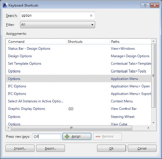
FIGURE 14.7 Editing your keyboard shortcuts
Copy a 3D view between projects. Suppose you made the perfect 3D view in your last project, and you can’t figure out how to get it into your current project. Fortunately, there’s a way to copy views from one project to another. Open both files in the same instance of Revit Architecture, and then do the following:
- In your perfect view, right-click the 3D view in the Project Browser, and choose Show Camera from the context menu.
- Press Ctrl+C to copy the selected camera.
- In your new model, press Ctrl+V and click in the view to paste the camera. The view and all its settings are now there (alternatively you can use the Modify
 Paste Aligned to Current View to paste the view).
Disallow joining for walls. By default, Revit Architecture will join walls that intersect; however, you will eventually run into a condition where you need to override this behavior. First select a wall and hover over the Drag Wall End grip. Then right-click and choose Disallow Join. This will unjoin the wall and give you additional control to drag the wall end without it automatically jumping and joining to the intersecting wall.
Join geometry on parallel walls. If you have two parallel walls and there is an opening hosted on one wall (such as a door or window), you may want to automatically cut an opening through the second wall as well. If the walls are close enough, around 1′-0″ (300 mm) of each other, you can use the Join Geometry tool between the two walls. After that, an opening will be cut in the other parallel wall and move with the original family (Figure 14.8).
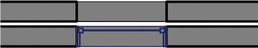
FIGURE 14.8 Join geometry
Prevent room numbers from shifting on cut/paste. By default, when you cut and paste rooms in a project, the room numbers will shift to the next available numbers. There is a trick to maintain the room numbers when cutting and pasting. Select the rooms you will be cutting to the Clipboard and create a group. Once the rooms are in a group, they can be cut and pasted without changing the room numbers. Then they can be ungrouped, and the group can be deleted from the Project Browser.
Copy objects from a Revit link. Need to copy an object from a Revit link and paste it into the host project? No problem; simply hover over the object in the link you want to copy and press the Tab key until the object is highlighted. Then click to select the object and use the standard copy and paste commands. The element will be copied from the link and pasted directly into the host project, where it can be directly manipulated (Figure 14.9).
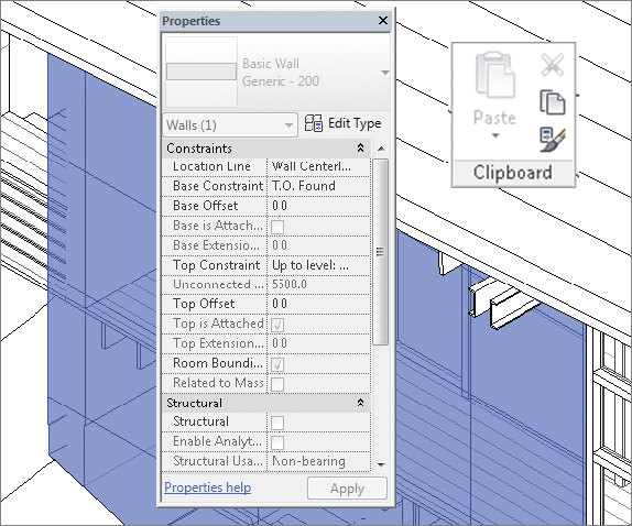
FIGURE 14.9 Copying from a link
Show annotation from a Revit link. Some annotation objects can be displayed from a Revit link. If the link contains annotation (such as room tags, dimensions, and so on) and you want to display it in the host project, set the Visibility/Graphic Overrides properties for the Revit link to By Linked View or Custom. You can further customize which view is displayed by adjusting the Linked View name on the Basics tab.
Locate Additional Resources
A number of resources are available to help you along the way and improve your use of the software, help you solve problems, and assist you in creating new content. There is a wealth of information online to help you learn or communicate with users far and wide. So, before you spend hours trying to solve a particularly challenging problem on your own, you might check some of these tools:
Revit Architecture Help Open the Revit Architecture Help by clicking the question-mark icon in the upper-right corner of the application. This tool will give you a basic synopsis of all the tools, buttons, and commands available in the application. It is available as a wiki at http://wikihelp.autodesk.com/Revit.
Subscription Support If you have purchased Revit Architecture on subscription, Revit Subscription Support offers web-based support. Its responses are speedy, its advice is top-notch, and chances are the support staff has seen your problem before. You can access Subscription Support at http://subscription.autodesk.com.
AUGI Autodesk User Group International (AUGI) is a source for tips and tricks as well as excellent user forums. The forums are free to participate in, and it’s a great place where you can ask questions, find answers, and discuss project workflows. AUGI is located at www.augi.com. Once you’re there, look for Revit Architecture.
Revit Forum Revit Forum is an ever-growing resource with forums and collections of blog posts and has many experienced Revit users regularly participating. Registration is free, and the forums are an extremely valuable resource for common issues and workflow recommendations. Revit Forum is located at www.revitforum.org.
YouTube Here’s a great reason to tell your IT department you need access to YouTube. Autodesk has its own channel with great free content: www.youtube.com/user/autodesk. It has hundreds of short videos showing how to perform specific tasks in Revit Architecture.
AECbytes AECbytes is a website dedicated to following the trends in the AEC industry, with a strong focus on BIM, technology, and the direction of the industry. The site is put together by Lachmi Khemlani; see www.aecbytes.com.