Chapter 1
Introducing the Autodesk Revit Architecture Interface
After more than a decade of use in the architecture, engineering, and construction (AEC) industry, Autodesk® Revit® Architecture software continues to be unique in its holistic building information modeling (BIM) approach to design. There are other tools that allow you to design in 3D, and 10 years ago 3D might have been a differentiator, but today 3D is the standard. BIM is quickly becoming the standard as well.
Revit Architecture provides the unique ability to design, update, and document your project information from within a single file — something no other BIM tool allows you to do. Because all of your data resides in a single project file, you can work in any view to edit your model — plan, section, elevation, 3D, sheets, details, even a schedule — and then watch as your file updates in all views automatically. To begin your journey of learning Revit Architecture, we’ll help you become comfortable with the user interface and the basic steps of the Revit Architecture workflow.
In this chapter, you’ll learn to:
- Use the Properties palette
- Use the Project Browser
- Use the View Control Bar
- Navigate with the ViewCube
- Create floors, walls, and levels
- Change a wall type
- Place doors and windows
- Space elements equally
Understanding the User Interface
The user interface (UI) of Revit Architecture is similar to other Autodesk products such as the Autodesk® AutoCAD®, Autodesk® Inventor, and Autodesk® 3ds Max® products. You might also notice that it’s similar to Windows-based applications such as Microsoft Word. All of these applications are based on the “ribbon” concept: Toolbars are placed on tabs in a ribbon across the top of the screen. The ribbon is contextually updated based on the elements you have selected. We’ll cover the most critical aspects of the UI in this section, but we won’t provide an exhaustive review of all toolbars and commands. You’ll gain experience with a variety of tools as you read the chapters and go through the exercises in this book.
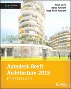
Figure 1.1 shows the Revit Architecture UI with labels illustrating the major UI elements. Four project views are tiled to display at the same time: plan, elevation, 3D, and perspective camera.
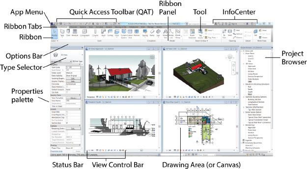
FIGURE 1.1 Revit Architecture user interface
Exercise 1.1: Use the Properties Palette to See Dynamic Updates of Properties
The Properties palette is a floating palette that remains open while you work in the model. The palette dynamically updates to show the properties of the element you have selected. If you have nothing selected, then the view’s properties are displayed.
To begin, go to the book’s web page at www.sybex.com/go/revit2015essentials, download the files for Chapter 1, and open the file c01-ex-01.1start.rvt. You can open a Revit Architecture project file by dragging it directly into the application or by using the Open command from the Application menu.
- Go to the Modify tab of the ribbon, find the Properties panel on the far left side of the ribbon, and click the Properties button. This button will open or close the Properties palette. Leave the Properties palette open.
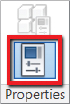
- Go to the View tab of the ribbon, find the Windows panel to the far right, click the User Interface button, and uncheck or check the Properties option. This will also open or close the Properties palette. Leave the Properties palette open.
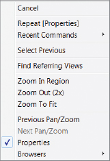
- Move your mouse into the drawing area, or canvas, and then right-click with the mouse; this will bring up a context menu. Click the word Properties near the bottom of the list. This will also open or close the Properties palette.
- You can also toggle the visibility of the Properties palette by pressing Ctrl+1 on your keyboard.
- The palette can be docked on either side of your screen or left floating in your canvas. To move the palette, just click the Properties palette header and drag it with your mouse. You will see an outline preview of the palette to aid you in placement; release the mouse button to place the palette.
- To dock the palette back to the left side of the screen, click and drag the mouse all the way to the left side of the screen, until the preview outline spans the entire height of the screen. The Properties palette may be up against the Project Browser. You will move the browser to the right side of the screen in the next section. See Figure 1.2.
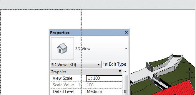
FIGURE 1.2 Preview of docking the Properties palette to the left side
- Make sure you don’t have any elements selected; look in the Properties palette and notice that it displays the properties of the active view, the 3D view. Use the scroll bar on the right side of the Properties palette to find the Extents group of properties. Check the Crop View option. You don’t need to use the Apply button to commit the change; instead just move your mouse into the canvas to automatically apply your changes.
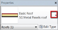
- Select the red roof in the 3D view. Notice that the Properties palette updates to show the properties of the current selection, the Basic Roof SG Metal Panels Roof. Any changes to these properties will affect this Roof element only.
- While you still have the roof selected, click the Type Selector drop-down at the top of the Properties palette. Choose the Warm Roof - Timber option from the list. Click your mouse off into space to deselect the roof. You’ll notice that the roof is no longer red. When you choose another type from the list, you are swapping the current roof type for another roof with different type properties, but the element properties stay the same!
This concludes Exercise 1.1. You can compare your results with the sample file c01-ex-01.1end.rvt available in the files you downloaded from the Sybex website.
Exercise 1.2: Explore the Content of Your Project with the Project Browser
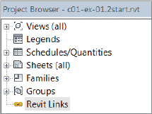
The Project Browser (refer back to Figure 1.1) is a table of contents for your project. The structure of the browser is a tree consisting of all the views, legends, schedules, renderings, sheets, families, groups, and links in your Revit Architecture project.
To begin the next exercise, open the file c01-ex-01.2start.rvt from the files you downloaded.
- Much like the Properties palette, the Project Browser can be docked on either side of the Revit canvas. Follow steps 5 and 6 in the previous exercise, but drag the Browser to the right of the canvas as in Figure 1.1.
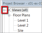
- The Project Browser is set up as a tree view with + and − icons to expand or collapse the tree structure. Find the very top node of the Browser named Views (All). Click the - icon found to the left of the Views (All) node.
- Now click the − icon next to the other top-level nodes: Legends, Schedules/Quantities, Sheets (All), Families, Groups, and Revit Links. Now your Project Browser looks very small, but in reality there are many pieces of content loaded in the current project.
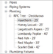
- Expand the Families node. Find the Planting folder and expand that. Then expand the RPC Tree - Deciduous folder.
- Find the Hawthorn − 25′ family. Click the text, and drag your mouse onto the canvas. Release the mouse button, and you will see an outline preview to help you place the tree. Click again to place the tree anywhere on the green landscape. The browser allows this nice drag-and-drop workflow for placing content!
- The Project Browser has a search utility as well. If you right-click any element in the Browser, you will see a Search option at the bottom of the context menu. Click Search, and in the dialog that appears type Kitchen; then click the Next button. The search utility opens folders to find any project content with the word Kitchen in the title. Find the Rendering: Kitchen view under Sheets (All)
 A001 - Title Sheet (Figure 1.3).
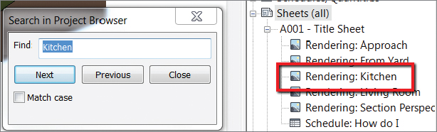
FIGURE 1.3 Project Browser search results for Kitchen
- Once you’ve found the Rendering: Kitchen view, close the Search In Project Browser dialog and open the Kitchen view by double-clicking the view name in the Project Browser. A very nice rendering opens; read Chapter 9 to learn how to use Revit’s rendering features.
This concludes Exercise 1.2. You can compare your results with the sample file c01-ex-01.2end.rvt in the files you downloaded for this chapter.
Exercise 1.3: Use the View Control Bar to See Frequently Used View Properties
The View Control Bar is at the bottom-left corner of every view. It is a shortcut for frequently used view properties. In most cases you can find the same parameter in the Properties palette for the current view. It is important to note that these commands affect only the currently active view (Figure 1.4).

FIGURE 1.4 The View Control Bar for a 3D view
Open the file c01-ex-01.3start.rvt to begin this exercise.
- Hover your mouse over the icons on the View Control Bar to see a tooltip, which displays the name of the specific tool. The first icon is Scale, and the second is Detail Level; we won’t be changing these view properties in this exercise.
- The third icon is a cube called Visual Style; click this icon and choose Realistic from the list that pops up. Note that you now see material textures on the walls and site if you zoom in closely. Also, the trees look more realistic.
- Click the Visual Style icon again; this time click Hidden Line from the list. This is a more traditional black-and-white style for viewing your 3D model.
- The next icon on the View Control Bar is Sun Path; skip this one. The next icon is Shadows; click this icon and you should see shadows render in your scene.
- The next icon is a teapot, and it launches the Rendering dialog. The rendering workflow is covered in Chapter 9. Click the teapot icon again to close the Rendering dialog.
- The next icon is Crop View. This is a very important tool, so click it now. You should see parts of your model around the corners disappear! The model is not deleted, just cropped.
- The next icon on the View Control Bar is Show Crop Region. Click this to see the crop box for the view. Now that you see it, select it and use the blue grips that appear to adjust your crop as you desire. See Figure 1.5 for an example.
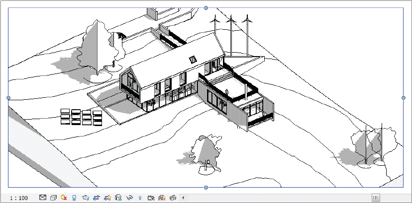
FIGURE 1.5 The Show Crop Region tool and the View Control Bar
- The next icon is Lock 3D View. This option is available only in 3D views. The command is helpful if you ever add text to a 3D view and you don’t want the viewpoint to change.
- The next icon looks like sunglasses. The Temporary Hide/Isolate tool is very useful as your project grows more complex. Select the roof in your project, and then click the sunglasses. Choose the option Isolate Element from the dialog. Notice that all other elements in the view are hidden so you can focus on the roof only. Click the sunglasses again, and choose Reset Temporary Hide/Isolate. Now your view is back to normal.
- The next icon in the View Control Bar is the light bulb, for Reveal Hidden Elements mode. Click the light bulb and a magenta border surrounds your view. Any element that is hidden, or turned off, will also be displayed with magenta lines. This viewing mode will prove very helpful in locating elements that appear in some views but not your current view. Click the light bulb on the View Control Bar again to return to your normal working mode.
There are other tools on the View Control Bar, but they aren’t used frequently enough to be discussed at this time. This concludes Exercise 1.3. You can compare your results with the sample file c01-ex-01.3end.rvt in the files you downloaded previously.
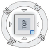
Exercise 1.4: Navigate with the ViewCube
As one of several navigation aids in Revit Architecture, the ViewCube is located in the upper-right corner of 3D views. This is a familiar UI element that appears in many Autodesk products.
To begin this exercise, open the file c01-ex-01.4start.rvt.
- Click the face of the ViewCube that is labeled Front. The view dynamically orbits to show a straight-on, elevation-style view of your project — and it will automatically fit the view to the entire model.
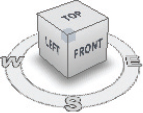
- Move your mouse over the ViewCube. As you hover the mouse, arrows appear on each side of the Front face. Click the arrow to the left of the Front face. The view will dynamically orbit to the Left elevation of your project.
- Hover your mouse over the ViewCube again; this time click the arrow above the ViewCube. This will take you to a Top view, or plan view orientation, of your project.
- Hover your mouse over the lower-right corner of the ViewCube top. Click this corner and the view will dynamically orbit back to a 3/4 corner view like you started out in.
- Now click your mouse anywhere on the ViewCube and drag the mouse. This is a custom orbit, not a predefined angle like Front, Left, or Top. Notice that a green Pivot icon appears at the center of the model. Release the mouse when you like your camera angle. The model does not Zoom To Fit with this type of orbiting.
- Select one of the trees in the model; then click and drag the ViewCube again. Notice that the green Pivot icon is now in the middle of the selected element. This is a very useful technique for navigating large models if you’re editing a specific element.
 If you are using a mouse, then the scroll wheel is ideal for zooming in and out. If you don’t have a mouse, the Zoom controls are all under the magnifying glass near the ViewCube.
- Once you’ve navigated the view and you’re satisfied with the camera angle, it is important to save the current viewpoint. Hover your mouse anywhere over the ViewCube and right-click. Select the Save View option from the context menu. Name your view (preferably something specific), and click OK.
- This will save the angle but not the zoom level. If you want to maintain a certain zoom level, use the View Crop commands covered in steps 6 and 7 of the previous exercise to limit the view to what is most relevant.
This concludes Exercise 1.4. You can compare your results with the sample file c01-ex-01.4end.rvt.
Creating a Simple Layout
In this section, you’ll use the Revit Architecture interface to complete basic modeling workflows. You can apply the basic concepts in these exercises to a variety of tools throughout the program.
Exercise 1.5: Create a Floor
To begin, open the file c01-ex-01.5start.rvt from the files you downloaded at the beginning of this chapter.
- The project opens in a floor plan view. There are a series of green reference planes for you to use as guides for this exercise. Click the Architecture tab of the ribbon, and find the Floor tool in the Build panel; click the Floor tool to enter Floor sketch mode.

- Note that the ribbon adjusts to indicate that you are in a sketch mode. The most obvious indication is the Mode panel with the red X and green check mark icons. These allow you to cancel out of sketch mode or commit your changes. You need to draw your floor shape before you click the green check mark.

- The Draw gallery to the right of the Mode panel has many different drawing tools. You’ll use the Pick Lines tool since there are reference lines already in place. Click the second-to-last icon in the lower-right corner of the Draw gallery.
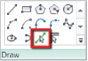
- Hover your mouse over one of the reference lines, and notice that it highlights to show a preview of the line that will be created. Click each of the reference lines only once. A pink sketch line appears after each click. When you’re finished you should see an image similar to Figure 1.6.
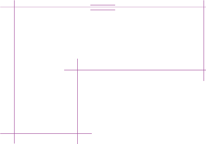
FIGURE 1.6 Floor sketch lines based on reference planes
- Try clicking the green check mark in the ribbon to commit your sketch lines. You will get an error about intersecting lines. Click Continue, and you will resolve this error. Revit requires that sketches be closed loops, and you have overlapping intersections at each of the corners.
- Find the Trim/Extend To Corner tool in the Modify panel of the Modify | Create Floor Boundary tab in the ribbon. Click the tool and hover your mouse over a portion of one of the sketch lines that you want to keep; it highlights blue. Then click the line. Next, click the portion of the intersecting line that you wish to keep. Revit will trim the unwanted segments from the corner.
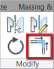
- After the first corner is cleaned up, Revit remains in the Trim/Extend To Corner tool; click the next two intersecting lines to clean up their corner. Repeat these steps until each corner is cleaned up, as in Figure 1.7.
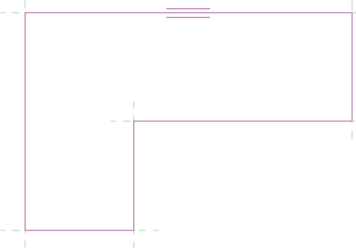
FIGURE 1.7 Floor sketch lines after trimming the corners
- Finally, click the green check mark; this time you should be successful. Revit has the floor selected when you exit sketch mode. You should see the blue selection color, and you can review your floor’s properties in the Properties palette. The floor is on Level 1, and its Area is 2500 SF (762 m).
This concludes Exercise 1.5. You can compare your results with the sample file c01-ex-01.5end.rvt.
Exercise 1.6: Create Walls
Open the file c01-ex-01.6start.rvt to start this exercise.
- Find the Wall tool in the Architecture tab of the ribbon. Click the Wall tool and choose the Pick Lines tool from the Draw gallery.

- Turn your attention to the Properties palette. You will set a few parameters before you draw your walls. Change the Location Line parameter by clicking in the cell and choosing Finish Face: Exterior from the drop-down list.
- Also in the Properties palette, change the Top Constraint parameter to Up To Level: Level 2.
- Now hover your mouse over one of the edges of the floor. Do not click your mouse yet. Notice the light-blue dotted line that appears. This line indicates whether the wall will be placed inward or outward from the reference line. Note that you may need to zoom in to see the blue dotted line.
- You want your walls to be inward from the green reference line, so move your mouse slightly inward from the floor edges — until the blue dotted line is on the inside — then click your mouse. Repeat for each edge until your drawing looks similar to Figure 1.8.
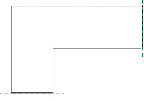
FIGURE 1.8 Walls placed inward from the floor edge
This concludes Exercise 1.6. You can compare your results with the sample file c01-ex-01.6end.rvt.
Exercise 1.7: Create Levels
In Revit Architecture, project datums are very important. Reference planes, grids, and levels are considered datums. These elements are usually visible only in a 2D view. They can be used to move any model element that references them.
To begin, open the file c01-ex-01.7start.rvt.
- In the Project Browser, under the Views (All) node, locate the Elevations (Building Elevation) node, and double-click the North view. You may need to click the + symbol to expand the tree.
- Zoom in to the right side of the view, and note the graphic representation of Level 1 and Level 2. Select the level line for Level 2, and notice that both the name of the level and the elevation value turn blue.
- Click the elevation value for Level 2, and change it from 10′-0″ (3000 mm) to 15′-0″ (4500 mm). Zoom out so you can see the walls. Notice that the walls automatically adjust to the new height of Level 2! This happens because the Level datum drives the Top Constraint parameter that was set when the walls were created.

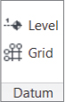 Go to the Architecture tab in the ribbon, a nd find the Datum panel. Click the Level command. Choose the Pick Lines tool from the Draw gallery.
- Turn your attention to the Options Bar just below the ribbon. Verify that the Make Plan View check box is checked. Then change the Offset value to 15′-0″ (4.57 m).
- Move your mouse into the drawing area and hover over the elevation line of Level 2. Wait until you see the light-blue dotted line appear above Level 2. If you don’t see the preview line, then move your mouse slightly up. Click to place your new level.
- Revit automatically names the new level for you based on the last level created. So in this case, Level 3 is the correct sequence and you don’t need to rename it. If you did want to rename the new level, you’d select the level line and click the level name after it turns blue. Press Esc to exit the Level tool.
- Select Level 3, and click the Copy tool on the Modify tab in the ribbon. Click anywhere in the canvas to specify a st art point for the Copy command; then move the mouse in an upward direction. Type 12′-0″ (3.657 m), and then press Enter to complete the command. Note that you can press and hold the Shift key to force Copy or Move commands to operate in 6″ (100 mm) increments.

- Select the newest level, and change the name to Roof. Note that the level symbol is black, not blue like the others. This means there is not a corresponding plan view for this level.
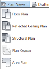
- Go to the View tab in the ribbon, find the Create panel, click Plan Views, and then click Floor Plan. The New Floor Plan dialog appears. Only levels that don’t have views are listed. In this case, you should see only the Roof level. Click OK to create a new view associated with this level.
 The new floor plan for the Roof level opens. Go to the View tab of the ribbon, locate the Windows panel, and click Switch Windows. This drop-down list shows all of the views you currently have open. You can click any view to switch to it.
 This concludes Exercise 1.7. You can compare your results with the sample file
 c01-ex-01.7end.rvt.
Exercise 1.8: Change Wall Type
In the previous exercise, you created an additional level, thus increasing the overall height of your building. In the following steps, you’ll adjust the top constraint of the walls and use the Type Selector to swap generic walls for a more specific wall type.
To begin, open the file c01-ex-01.8start.rvt.
- Go to the View tab of the ribbon, find the Create panel, and click the 3D view icon. Also you can click Default 3D View in the QAT, or double-click the {3D} view in the Project Browser.

- Click the Close Hidden Windows button in the QAT, and then activate the South view under Elevations (Building Elevation) from the Project Browser.
- From the View tab in the ribbon, locate the Windows panel, and then click the Tile Windows button. You can also use the keyboard shortcut WT. You should see the two active views (default 3D view and South elevation) side by side.
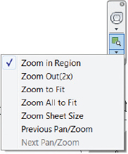
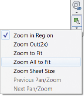
 In either view, find the Navigation bar, click the drop-down arrow under the Zoom icon, and then click Zoom All To Fit. You can also use the keyboard shortcut ZA.
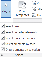
- Find the Modify button at the far left side of the ribbon. Click the Select button under the Modify button and a drop-down appears. Make sure that the Select Elements By Face option is checked. This will enable easier selection of walls.
- Click inside the 3D view window to activate the view. Hover the mouse pointer over any of the walls. Press the Tab key once, and all of the walls should highlight, as in Figure 1.9. The status bar should indicate “Chain of walls or lines.” Click the mouse once to select the chain of walls.
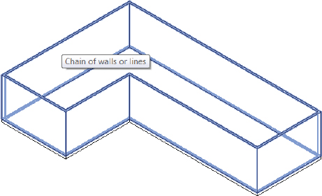
FIGURE 1.9 Highlighted walls of a chain selection
- With the walls still selected, turn your attention to the Properties palette. Find the parameter Top Constraint. Change the value to Up To Level: Roof, and then click Apply, or move your mouse into the canvas to automatically apply it. Notice how the walls change height in both the 3D view and the elevation view (Figure 1.10).
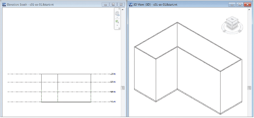
FIGURE 1.10 Tiled windows show the result of modifying the top constraints of the walls.
- Review Figure 1.1 to see the intended image. In the 3D view, select the wall that corresponds to the Front face of the ViewCube. Press and hold the Ctrl key, and select the wall segments adjacent to it, as in Figure 1.11.
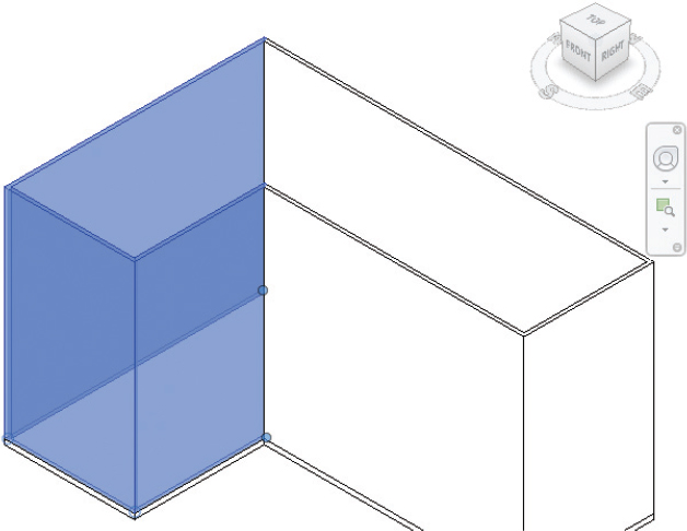
FIGURE 1.11 Use the Ctrl key to manually select multiple items in your model.
- With the walls selected, look to the top of the Properties palette to find the Type Selector. Note that it is reporting that the wall type of the current selection set is Basic Wall Generic − 8″ (200 mm). Click the Type Selector to open a list of wall types in the project. Choose the Exterior - Brick On CMU wall type near the top of the list.
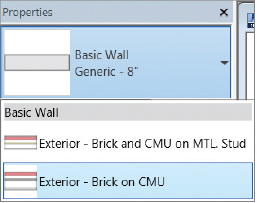
- Zoom into the walls for which you just swapped types. The thickness of these three walls should update to inherit the properties of the type you chose. Also, if you zoom in close enough, you should see a brick pattern on the walls, which the Generic walls did not have.
This concludes Exercise 1.8. You can compare your results with the sample file c01-ex-01.8end.rvt.
Exercise 1.9: Place Interior Walls
Open the file c01-ex-01.9start.rvt to begin this exercise.
- From the Architecture tab in the ribbon, click the Wall tool. Use the Type Selector to change the wall type — before placing the walls — to Interior − 4 7/8″ (123 mm) Partition (1-hr).
- In the Draw gallery in the ribbon, choose the Pick Lines icon; then click each of the green reference planes that have been provided as guides for interior walls. Your results should resemble Figure 1.12.
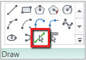
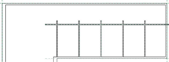
FIGURE 1.12 The interior walls
- Choose the Trim/Extend Multiple Elements tool from the Modify tab of the ribbon. Select the long horizontal interior wall first. Then move your mouse inside the room on the lower-right side of the plan. Hold your mouse button down and drag a crossing selection window up and to the left to include each of the smaller segments of wall. Release the mouse, and Revit should trim off the walls neatly, as in Figure 1.13.
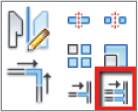
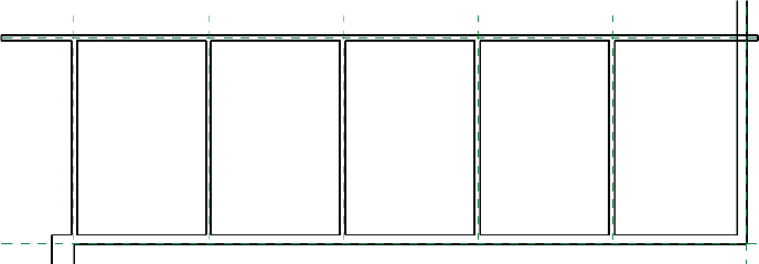
FIGURE 1.13 Results of Trim/Extend Multiple Elements
- Select the Trim/Extend Single Element tool from the Modify tab of the ribbon. First, click the exterior wall to the far right of the plan. Then click the intersecting interior wall. Remember, Revit’s Trim tool wants you to click the segments you want to keep.
- Now select the Trim/Extend To Corner tool from the Modify tab. Click the remaining overlapping corners to clean up the wall construction.
- No te that the leftmost interior wall is not aligned with the thicker Brick On CMU wall. Click the Align tool from the Modify tab of the ribbon. First, click the inside edge of the thicker wall because that is what you want to align to. The second click should be on the outside edge of the leftmost interior wall. This is what you want to move. The results should resemble Figure 1.14.

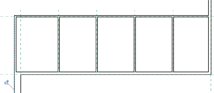
FIGURE 1.14 Results of the Align tool
This concludes Exercise 1.9. You can compare your results with the sample file c01-ex-01.9end.rvt.
Exercise 1.10: Place Doors and Windows
In this exercise, you’ll place doors and windows in the walls. Doors and windows require a wall to host them. You’ll use the generic Door and Window families that are loaded in the project, but bear in mind that families of any size, material, and configuration can be used in Revit.
To begin, open the file c01-ex-01.10start.rvt.
 Go to the Architecture tab and locate the Door tool. Click the tool and notice that the Type Selector reports that the Door type is Single-Flush 36″ (914 mm) × 84″ 2133 mm).
- Hover the mouse over one of the interior walls, and you’ll see a preview of the door being placed in the wall. Press the spacebar and notice that the door flips the direction in which it is swinging.
- Move the mouse more toward the inside of the room, and press the spacebar until your door swings into the room and is swinging in the correct direction. Click to place the door.
- Repeat the same steps to place doors into the other rooms along the interior wall. When you finish, the results should appear similar to Figure 1.15.
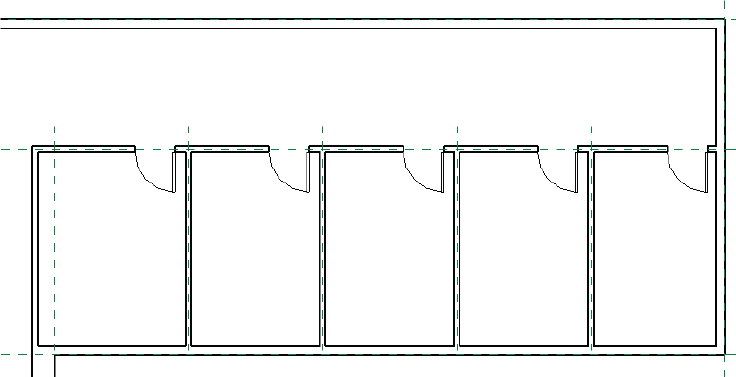
FIGURE 1.15 The doors swing into the rooms.
- Go back to the Architecture tab of the ribbon and locate the Window tool. Click the tool and notice that the Type Selector reports that the Window type is Fixed 36″ (914 mm) × 48″ (1219 mm).

- Hover the mouse over one of the exterior walls between the interior walls, and you’ll see a preview of the window being placed in the wall. Move the mouse inside the wall to make the window pane closer to the inside of the room as well. Click to place the window.
- Repeat the same steps to place windows along the exterior wall for each of the interior rooms. When you finish, the results should appear similar to Figure 1.16.
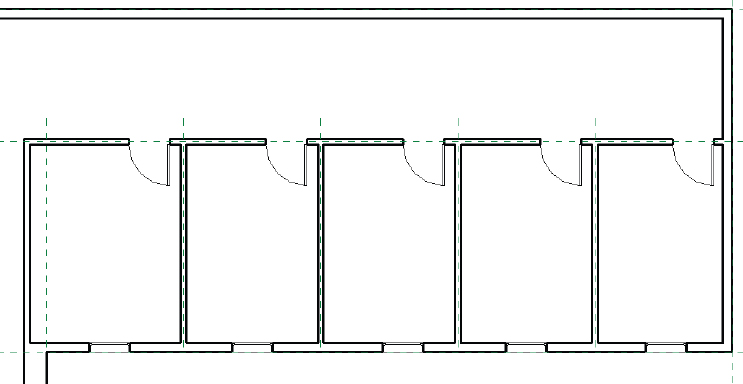
FIGURE 1.16 The Windows for the rooms
This concludes Exercise 1.10. You can compare your results with the sample file c01-ex-01.10end.rvt.
Exercise 1.11: Space Elements Equally
In this exercise, you’ll use dimensions and temporary dimensions to create an equally spaced relationship between the interior walls, then the doors, and then the windows. This will illustrate the idea of using constraints to create design intent. This is a fundamental concept of Revit’s parametric modeling.
Open the file c01-ex-01.11start.rvt to begin this exercise.
- From the Annotate tab in the ribbon, locate the Dimension panel, and click the Aligned Dimension tool. In the Options Bar, notice that the Placement drop-down is set for Wall Centerlines. Click in this drop-down and change the placement to Wall Faces.

- Hover your mouse over the leftmost interior wall, and you should see the outside edge highlight. Click to start a dimension string.
- Return your attention to the Options Bar and change the placement from Wall Faces to Wall Centerlines.
- Move your mouse back into the canvas and hover over the center of the interior walls until you see a blue highlight in the center of the interior walls. Click to continue your dimension string. Repeat for each interior wall.
- Return to the Options Bar and change the placement from Wall Centerlines to Wall Faces. Click the inside face of the exterior wall to finish adding dimensions to your dimension string.
- Move your mouse above the interior wall and click to place the dimension string in the view. The results should resemble Figure 1.17.


FIGURE 1.17 The dimensions of the interior walls
- After placing the dimension string, notice the blue EQ icon that appears. This is a valuable shortcut for spacing your elements evenly. Click this icon and your walls will automatically space themselves evenly.
- You will most likely get an error because of a door overlapping with a wall. Disregard this warning by closing the small dialog that opens in the lower-right corner. We will use temporary dimensions to help space the doors in the next step. Click the Esc key twice to exit the Dimension tool.
- Select the rightmost door, and notice the light-blue dimensions that appear. These are called temp dims and are very helpful for locating doors and windows relative to walls. Notice that this door is 2′-6″ (.76m) from the wall. This is perfect; leave it as is.
- Select the next door to the left and hover your mouse over the temp dim that appears. The tooltip lets you know you can edit this dimension. Click the blue text and type 2′-6″ (.76m) into the text box. The door moves to the correct location. Follow these steps for the other doors. The results should resemble Figure 1.18.
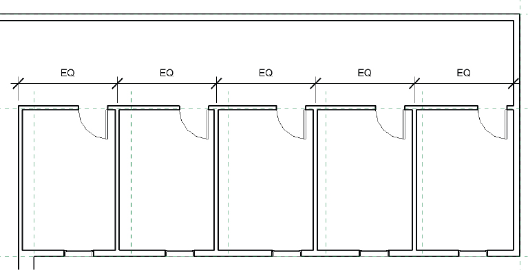
FIGURE 1.18 Doors equally spaced relative to the walls
- Now you will combine the techniques of using dimensions and temp dims to space the windows equally. Select the rightmost window.
- The temp dim reference line spans from the center of the window to the center of the exterior wall — turn your attention to the blue circle icon at the center of the exterior wall. Click the blue circle icon once, and the circle jumps to the inside face of the wall. Click the same circle again, and the temp dim appears along the outside face of the exterior wall.
- Click the temp dim value and change it to 4′-8″ (1.42 m).
- Follow the same steps to make the center of the leftmost window 4′-8″(1.42 m) from the exterior face of the exterior wall.
- Click the Annotate tab of the ribbon, and choose the Aligned Dimension tool.
- Hover your mouse over the middle of the leftmost window. You should see a small vertical blue highlight appear, indicating the center of the window. Click to place a dimension reference there.
- Hover over the middle of the next window and click to continue your dimension string. Repeat until you have a dimension string between the centers of each of the windows.
- Move your mouse down below the wall, and click to place the dimension string in the view. Click the EQ button that appears. Press Esc to exit the Dimension tool. Your result should resemble Figure 1.19.
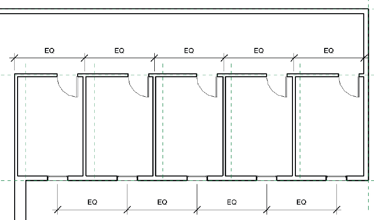
FIGURE 1.19 Windows equally spaced
This concludes Exercise 1.11. You can compare your results with the sample file c01-ex-01.11end.rvt.