Chapter 2
Walls and Curtain Walls
Walls in the Autodesk® Revit® Architecture software can range a great deal in complexity. Early in the design process, walls and curtain walls can be more generic, essentially serving as vertical containers for space and function. They can also be associated to masses in order to create incredibly complex shapes. As the design progresses, these generic walls and curtain walls can be swapped out for more specific vertical compound walls that indicate a range of materials as well as geometric sweeps and reveals.
In this chapter, you’ll learn to:
- Create walls using several different methods
- Host elements in walls
- Modify wall parameters
- Modify and reset wall profiles
- Create and customize a curtain wall
- Embed a curtain wall in a basic wall
- Add/remove grids and add a curtain wall door
Understanding Wall Types and Parameters
Revit Architecture has three fundamental types of walls: basic, stacked, and curtain walls. In this section, we will cover some of the important aspects of each. This is not intended to be an exhaustive guide to creating and editing each wall type but rather an overview to provide some background knowledge before we continue with the exercises throughout this chapter.
Basic Walls
The Revit Architecture default template includes several wall types. The most basic wall types have no detailed structure and are named with the prefix Generic for easy identification. Other wall types have highly detailed structures known as layers. Each layer is assigned a function, material, and thickness. The function of a wall layer determines how it will join when multiple wall types intersect or when a wall intersects another element such as a floor.
- On the Architecture tab in the ribbon, click the Wall tool.
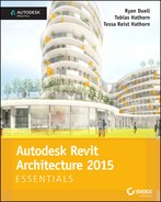
- In the Type Selector at the top of the Properties palette, select the Generic − 8″ (200 mm) Masonry wall type.
- Click Edit Type just below the Type Selector.
- Click the Preview button at the lower left in the Type Properties dialog to see a graphic sample of the wall type.
In Figure 2.1, the structural region of this wall is defined by a diagonal crosshatch pattern. This is a basic wall with only one pattern defining the wall’s material.
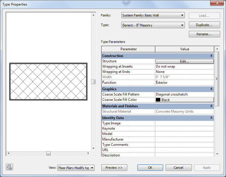
FIGURE 2.1 Masonry structural region of a basic wall
Basic walls can be modified to contain far more structural detail:
- With the Type Properties dialog still open, go to the Type drop-down.
- Select the wall type Exterior - Brick On Mtl. Stud, and you’ll see the difference (Figure 2.2).
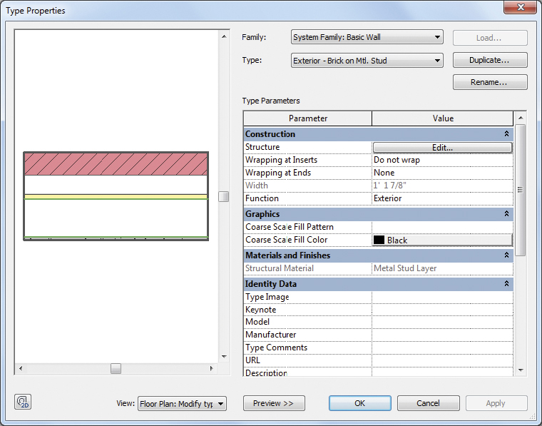
FIGURE 2.2 Compound walls consist of several layers of functional materials.
- Click the Edit button in the Structure parameter.
Basic walls can even have profiles applied to them that are used to add or remove geometry in your walls. If you’re still examining the structure of the previous wall, do the following:
- Click the Cancel button, and select the wall type Exterior - Brick And CMU On MTL. Stud.
- In the Preview pane, switch the View to Section.
- Zoom into the top of the wall sample shown in the preview.
- You’ll see a parapet cap at the top of the wall (Figure 2.3). This is a profile associated to the basic wall type.
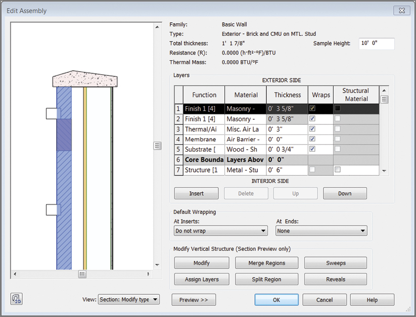
FIGURE 2.3 Wall sweep as part of a wall
- You’ll see a parapet cap at the top of the wall (Figure 2.3). This is a profile associated to the basic wall type.
Stacked Walls
Stacked walls consist of basic wall types but are combined vertically in a single defined type. Any basic walls can be used to create a stacked wall.
To find the stacked wall types, follow these steps:
- Start the Wall tool, access the Type Selector, and scroll to the bottom of the list.
- Select the wall type Exterior - Brick Over CMU w Metal Stud.
- Click the Edit Type button, and then click Structure Edit.
As shown in Figure 2.4, this wall type is defined by two different basic walls, but you can add more if necessary.
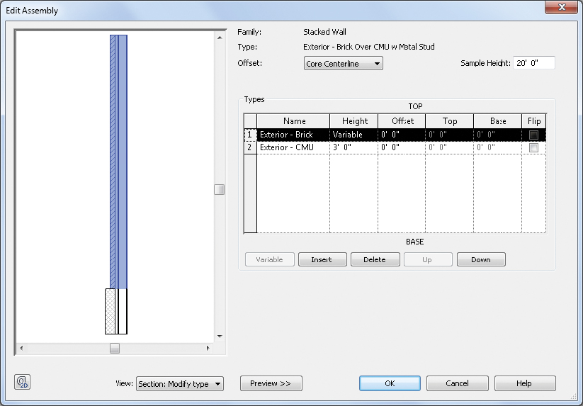
FIGURE 2.4 Type properties of a stacked wall
One of the stacked wall segments must be of variable height to accommodate the vertical constraints of the wall instances you place in a project. If all the segments were a fixed height, it would conflict with varying datum geometry in your project. In addition to specifying the height of the segments, you can also adjust the horizontal offset or set a segment to flip its orientation (inside or outside).
Stacked walls have a unique option available (select and then right-click) called Break Up. When a stacked wall is broken up, the segments are reduced to individual basic walls. The basic walls represent the same dimensions specified in the stacked wall.
Curtain Wall Types
Curtain walls are more complex than basic walls or stacked walls. They consist of four elements: a simple wall-segment definition, curtain grids, panels, and mullions. Curtain wall types can be completely instance based (allowing each to vary) or can be driven entirely by the wall type properties that set grid spacing, panels, and mullion types for interior and border conditions (Figure 2.5).
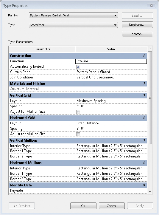
FIGURE 2.5 Curtain wall type definitions
Hosting Elements in Walls
Walls can host other types of elements that are meant to create openings. As long as the walls exist, the elements they are hosting exist as well. Doors and windows are examples of commonly used hosted elements.
Placing a door in a wall is very easy and can be done in plan, elevation, or 3D view. You may notice that you can place doors only in walls. This is because door families are hosted elements and cannot exist without a host. Because of this relationship, hosted elements are automatically deleted if you delete a host element such as a wall.
Creating Wall Configurations
The objective of the following exercise is to create several different wall configurations through drawing and picking existing geometry. The first method you will explore is manually drawing walls using some of the Draw shapes (Figure 2.6).
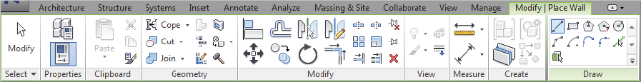
FIGURE 2.6 Generic configurations for walls
Then you will use additional wall tools to create arc shapes using Tangent End Arc and Fillet Arc configurations to append wall segments to existing wall elements.
Once the exterior walls are created, the last portion of the exercise will focus on creating walls by picking existing geometry to create walls.
Exercise 2.1: Create Wall Configurations
To begin, go to the book’s web page at www.sybex.com/go/revit2015essentials, download the files for Chapter 2, and open the file c02-ex-2.1start.rvt.
- Activate the floor plan named Drawing Walls. Start the Wall tool, and practice creating segments of walls using various tools in the Draw panel (such as Line or Center-Ends Arc). Don’t worry about where you create these walls; it’s just practice. Also take note of the settings available in the Options Bar prior to wall placement because they will vary for each tool.
- Activate the floor plan named Tangent-Fillet Walls. Your goal is to complete the layout of the walls according to the dashed lines shown in the floor plan.
- In the upper-right corner of the layout, the two perpendicular walls must be joined with a radius wall segment. Select either one of the wall segments, right-click, and select Create Similar from the context menu.
- On the Draw panel in the ribbon, select the Fillet Arc option. Click one wall segment and then the other perpendicular segment. After you click the second wall segment, a curved segment appears.
- Place the curved segment near the layout line. Before you continue, click the radial temporary dimension value and change it to 6′ (2000 mm).
- The Wall command should still be active, so select the two perpendicular walls in the lower-right corner of the layout, and repeat steps 4 and 5.
- With the Wall command remaining active, return to the Draw panel in the ribbon, and select the Tangent End Arc option. Click the left end of the wall segment at the bottom of the layout, and then click the left end of the wall segment at the top to complete the tangent arc wall. Your results should look like the plan shown in Figure 2.7.
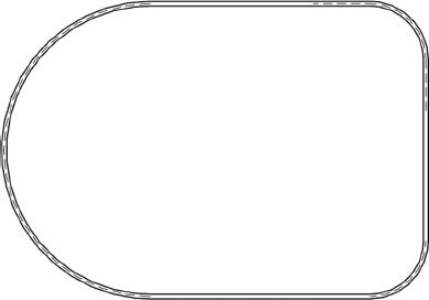
FIGURE 2.7 Results of the Tangent-Fillet Walls steps
- Activate the Picking Walls floor plan, and then start the Wall tool. Choose the Pick Lines option in the Draw panel in the ribbon. On the Options Bar, set the Location Line to position the wall in relation to the picked path.
- In the first set of lines in the sample file, pick each individual line segment to place walls.
- On the second set of lines, use the chain-select method to place all the wall segments at once. Hover your mouse pointer over one of the line segments, and press the Tab key once. When the chain of lines is highlighted, click the mouse button to place the complete chain of walls. Your results should look like the plan shown in Figure 2.8.

FIGURE 2.8 Result of Pick Lines
Exercise 2.2: Host a Door in a Wall
To begin, go to the book’s web page at www.sybex.com/go/revit2015essentials, download the files for Chapter 2, and open the file c02-ex-2.2start.rvt.
- Activate the floor plan named Existing Walls.
- Start the Door tool, and add three doors to the main horizontal wall to the left of the vertical walls.
- After placing a door, select the door and notice the temporary dimensions that appear.
- With the door still selected, adjust the temporary dimension so they are 9″ off the center of the perpendicular walls (left-click the temporary dimension Move Witness Line) to toggle the dimension witness line.
- Click the temporary dimension text, which allows you to enter 9″ (230 mm) (Figure 2.9).
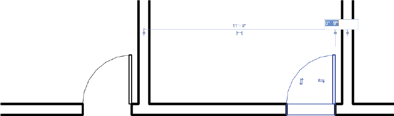
FIGURE 2.9 Hosting doors in a wall
Modifying Wall Parameters
Now that you’ve created a few wall configurations, it’s important to understand how you can modify them. Sometimes this is done simply by selecting the wall and dragging a wall end or a shape handle to a new position. In other cases, you want to be more exact and assign a specific value.
Your approach depends on where you are in the design process. Just remember that you can update design decisions, and all your views, schedules, tagging, and so forth will update—don’t get concerned with being too exact early in your design.
The objective of the following exercise is to modify existing wall type and instance parameters. You will start by modifying some type parameters of the wall. Then for the second part you will modify some instance parameters.
Exercise 2.3: Modify Wall Parameters
To begin, go to the book’s web page at www.sybex.com/go/revit2015essentials, download the files for Chapter 2, and open the file c02-ex-2.3start.rvt.
- Activate the floor plan named Level 1. Sketch a straight segment of a wall, but this time as you draw the wall, type 40 (or 12000 mm). Depending on the default units, typing 40 creates a 40′ segment.
- Notice that you didn’t have to indicate the units as feet. If you wanted to indicate inches, you’d only have to put a space between the first and second values. Thus, 40′-6″ can easily be entered as 40 (space) 6.
- Press the Esc key twice, or click the Modify button in the ribbon. Select the segment of wall you just created.
- There are two options to modify the length, as shown in Figure 2.10. You can type in a new value by selecting the temporary dimension and entering the value, or you can simply drag either wall end to a new location.

FIGURE 2.10 Modifying the wall length
- Open to the default 3D view by navigating to the View tab and clicking 3D View, and look at some other options. The two blue arrows at the top and bottom of the wall are called shape handles (Figure 2.11). You can click and drag them to adjust the top and bottom locations of a wall. As you drag the shape handle you will see a temporary location line until you release the shape handle.
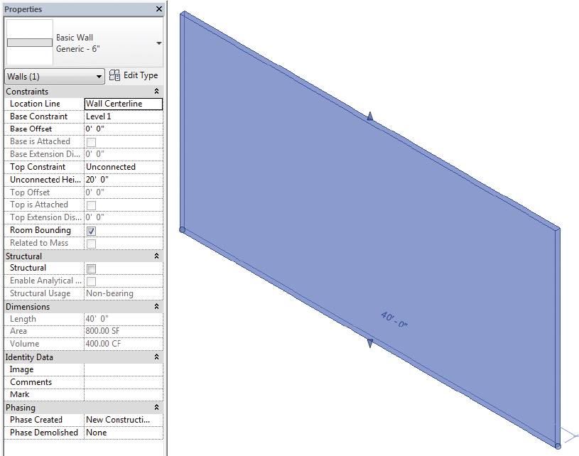
FIGURE 2.11 Shape handles and instance parameters displayed in the Properties palette
- Next, let’s look at the instance parameters. Changes to these parameters will update only the selected instance(s). First, select the wall and review the Properties palette. These are the specific instance parameters for this wall type.
- Update the Location Line parameter value to be Finish Face: Exterior. The location line is the origin of the wall. If you swap one wall for another, the location line will be maintained. In other words, if you create an exterior wall and the location line is the inside face, then when you change the properties or select a thicker wall, it will grow to the outside—away from the location line.
- Next, locate the Base Constraint parameter. Change the value to Level 2. The base constraint is the bottom of the wall. The base constraint can be changed at any time, and the wall will move to reflect the change.
- Locate the Base Offset parameter. Change the value to 1′-0″ (300 mm). The Base Offset or Top Offset is the value above or below the respective constraint (negative dimensions can also be used). For example, if you wanted the bottom of a wall associated to Level 1 but 3′-0″ (1 m) below, the value for Base Offset would be -3′-0″.
- Locate the Unconnected Height parameter. Change the value to 12′-0″ (3655 mm). The Unconnected Height value is the height of the wall when you do not use a specific datum for Top Constraint. If you change the Base Constraint parameter back to Level 1 and then change the Top Constraint value to Up To Level: Level 2, the Unconnected Height parameter becomes inactive.
Editing and Resetting Wall Profiles
Not all walls are rectilinear in elevation, and for these situations you can edit the profile of a wall. Note that you’ll be able to edit the profile of a straight wall only, not a curved wall.
When you edit a wall’s profile, the wall is temporarily converted to an outline sketch in elevation. Because the sketch is not plan based, you can edit a profile only in a section, an elevation, or an orthogonal 3D view. You can draw as many closed-loop sketches as you like within the wall’s profile, but each loop must be closed.
If you need to remove the edited condition of a wall, don’t reenter Edit Profile mode and manually remove the sketches. Select the wall, and click Reset Profile in the Mode panel on the Modify | Walls tab. Doing so will reset the extents of the wall and remove any interior sketches.
Another scenario for using Reset Profile would be when attempting to use Attach Top/Base. Depending on how the wall profile was originally edited, Revit could display a join error when attempting to attach the wall. This is most likely to occur if the top of the wall profile was edited previously. Reset the profile first, and then attempt to attach the wall to the roof as needed.
The objective of the following exercise is to edit the profile of a wall from a rectangle to a custom shape and reset the profile at the end of the exercise. Then you will continue with a second exercise using the Attach Top/Base tool to attach one wall to another wall. The last portion of this exercise will cover detaching the condition.
Exercise 2.4: Edit and Reset the Wall Profile
To begin, go to the book’s web page at www.sybex.com/go/revit2015essentials, download the files for Chapter 2, and open the file c02-ex-2.4start.rvt.
- The starting file should open to the default 3D view. Select the 40′ (12000 mm) wall, and click Edit Profile on the Modify | Walls tab.
- From the South Elevation view, create the sketch as shown in the top illustration in Figure 2.12.
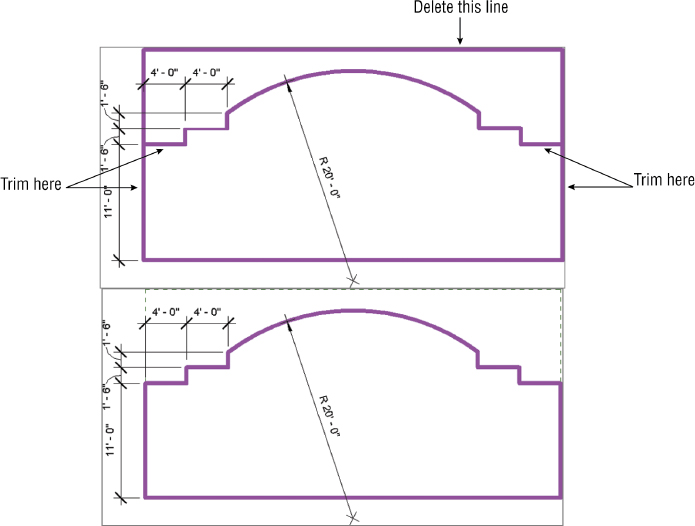
FIGURE 2.12 Adding new sketch lines
- Don’t worry about following the exact dimensions in this illustration—we’re just showing them for reference.
- Delete the top line, and trim the two side sketch lines.
- Note that the reference lines indicating the extents of the original wall remain, as shown in the bottom illustration in Figure 2.12.
- Use the Trim tools as necessary to clean up the sketch so that it remains as one closed loop.
- If you have crossing lines or open segments, you will receive an error when you attempt to finish the sketch in the next step.
- When you have finished, click Finish Edit Mode.
Should the design change later and you need to remove the custom wall profile, you can select the wall and use the Reset Profile tool on the ribbon.
Exercise 2.5: Attach and Detach the Top/Base
To begin, go to the book’s web page at www.sybex.com/go/revit2015essentials, download the files for Chapter 2, and open the file c02-ex-2.5start.rvt.
- The starting file should open to the default 3D view. Select the wall and click Edit Profile. Modify the profile sketch as shown in Figure 2.13. Don’t forget to trim and delete unnecessary sketch lines. Then finish the sketch.
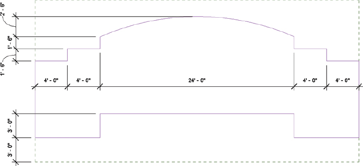
FIGURE 2.13 Edited wall profile
- Open the Level 1 floor plan, and sketch another wall right on top of the same location as the wall you just edited. In this case, use a Generic 12″ Masonry (305 mm) wall, and set the Unconnected Height in the Options Bar to 2′-0″ (610 mm).
- Open the default 3D view to complete this step. Select the thicker wall, click Attach Top/Base (Figure 2.14), and confirm that the Options Bar setting is correct for Top or Base. Now select the wall with the profile that you just edited. This attaches the top of the thicker wall to the underside of the upper wall, as shown on the right side of the figure.
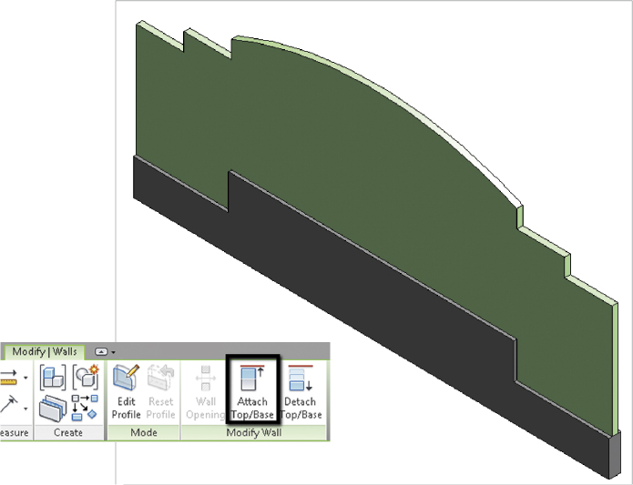
FIGURE 2.14 Attach Top/Base setting
- The great thing about this technique is that the relationships between the two walls are maintained if you edit the elevation profile of the upper wall. Performing these steps is a lot faster than having to edit the elevation profile of both walls! If you should need to detach the lower wall, follow the remaining steps in this exercise.
- Select Generic 12″ Masonry and click Detach Top/Base on the ribbon.
- Click the Generic 8″ wall above, or click Detach All on the ribbon to reset the wall back to the original 2′-0″ unconnected height.
Cutting Openings
Openings can be cut in both straight and curved walls. The Wall Opening command tends to be used in curved walls because you already have the option to edit the elevation profile in straight walls. And when you cut an opening, you cannot sketch beyond the extents of the wall boundary or create shapes that are not rectilinear.
The objective of the following exercise is to add and modify wall openings in a curved wall.
Exercise 2.6: Cut Openings in a Curved Wall
To begin, go to the book’s web page at www.sybex.com/go/revit2015essentials, download the files for Chapter 2, and open the file c02-ex-2.6start.rvt.
- The starting file should open to the default 3D view. Select the curved wall.
- The Wall Opening option appears on the Modify | Wall tab, as shown in Figure 2.15 on the left.
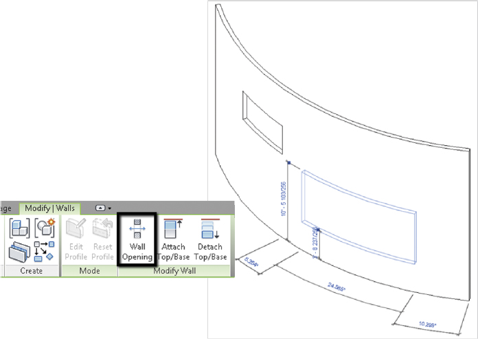
FIGURE 2.15 Creating wall openings
- The Wall Opening option appears on the Modify | Wall tab, as shown in Figure 2.15 on the left.
- Select this command, and then hover over the wall.
- You are prompted to create a rectilinear opening with two clicks, as shown in Figure 2.15 on the right.
- Create two wall openings anywhere in the arc wall.
- When the wall opening is selected, the Properties palette will display constraints such as Top Offset and Base Offset. This allows input for exact dimensions to modify the opening size and location.
- Set the Base Offset to 1′-0″ for one of the wall openings.
- If you need to delete an opening, hover over the opening edge and select it (or use the Tab key to toggle the selection) and then press the Delete key.
Splitting Walls
Sometimes, after you’ve created walls, you realize that you don’t need an inner segment—or you need to change a segment to another wall type. The process of deleting and re-creating walls would be tedious work. However, Revit Architecture offers a Split Element tool on the Modify tab of the ribbon that allows you to divide walls, effectively breaking them into smaller pieces. This can be done along both horizontal and vertical edges of either curved or straight walls (Figure 2.16).
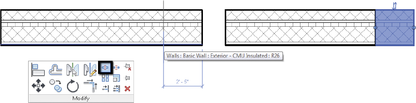
FIGURE 2.16 Splitting walls, before and after
Swapping Walls
Swapping walls for different types prevents the rework of deleting them and creating new ones. Doing so is as easy as selecting a wall and then selecting the new type from the Properties palette (Figure 2.17). This is especially useful early in the design process, when the exact wall type is likely to be unknown. Generic or placeholder wall types can be used and then swapped later on when the design progresses.
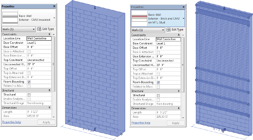
FIGURE 2.17 Swapping wall type before and after
Creating Curtain Walls
Curtain walls are created in much the same way as regular walls: by selecting the type of curtain wall and then sketching the desired shape. However, the available parameters for curtain walls vary from basic or stacked walls.
The objective of the following exercise is to customize a curtain wall that is instance-based (meaning you will not define any type parameters yet). You will manually add curtain grids that will subdivide the wall into smaller panels. The last part of the exercise will be to add curtain mullions, which are hosted to the curtain grids, and manually space the grids to the desired width.
Exercise 2.7: Create and Customize a Curtain Wall
To begin, open the book’s web page at www.sybex.com/go/revit2015essentials, download the files for chapter 2, and open the file c02-ex-2.7.start.rvt.
- The starting file should open to the default 3D view. Select the Curtain Grid tool from the Build panel on the Architecture tab of the ribbon.
- As you hover over the edge of the curtain wall, you are prompted with a dashed line that indicates where the grid will be placed. Also notice that the dashed line should snap at the midpoint and at one-third lengths from either end of the curtain wall.
- Using the default All Segments placement option on the ribbon, add three grid lines along the horizontal and vertical directions. At this point the curtain wall should look like Figure 2.18.

FIGURE 2.18 Completed curtain grid lines
- Now that you’ve added curtain grids, you can add mullions to the curtain panel. Select the Mullion tool from the Build panel, and choose the All Grid Lines placement option on the ribbon (Figure 2.18).
- Hover the cursor over any of the curtain grid lines, and they should all highlight, indicating where the mullions will be placed. Left-click and mullions will be assigned to all empty grid lines (in this example they should be added everywhere). Press the Esc key once to exit the command.
- Move the cursor over one of the vertical mullions and press the Tab key until the curtain grid line is highlighted. The Tab key is important when working with curtain walls. Because there are several elements that potentially share a common edge (walls, panels, grids, and mullions), it is necessary to press and release the Tab key to toggle what will be selected (Figure 2.19).
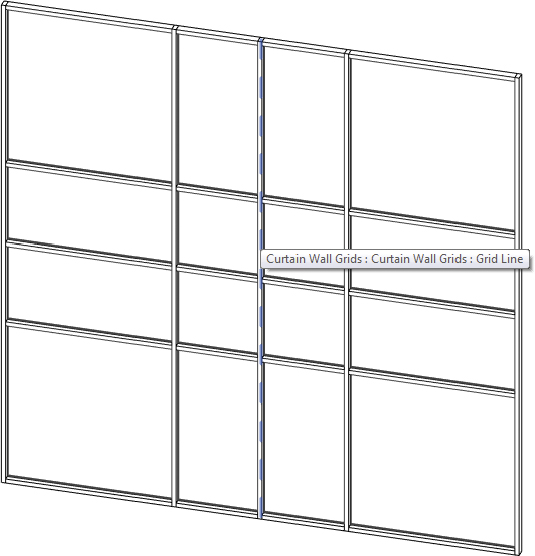
FIGURE 2.19 Mullions and selecting the grid line
- Once the grid line is highlighted, left-click to select it.
- Once it is selected, two temporary dimensions should be visible.
- Left-click the temporary dimension text; you can enter exact values to move the grid line to.
- Set the vertical first and last grid lines to be 2′-0″ from the curtain wall edge. Leave the center grid line where it is. Set the horizontal first and last grid lines to be 3′-0″ from the curtain wall edge.
When complete, the curtain wall should look like the one shown in Figure 2.20.
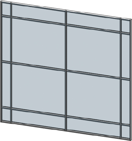
FIGURE 2.20 Final instance-based curtain wall
In the previous exercise you were able to modify the curtain grids and hosted mullion locations using temporary dimensions, since the curtain type properties did not have any set spacing parameters. In the next exercise the objective is to set some type property values for spacing and mullion types.
Exercise 2.8: Modify Curtain Wall Type Properties
To begin, go to the book’s web page at www.sybex.com/go/revit2015essentials, download the files for Chapter 2, and open the file c02-ex-2.8start.rvt.
- The starting file should open the to the default 3D view. Select one of the two curtain walls and click Edit Type in the Properties palette.
- Locate the Vertical Grid and Horizontal Grid settings for Layout (currently set to None). Set Vertical Grid Layout to Fixed Distance, Spacing 5′-0″. Set Horizontal Grid Layout to Maximum Spacing, Spacing 4′-0″. Click OK to close the Type Properties dialog.
- Both curtain walls should update to show grid lines at the spacing you configured (Figure 2.21).

FIGURE 2.21 Curtain wall grids added
- Select one of the curtain walls and click Edit Type again. Under Construction, set the Curtain Panel to System Panel : Solid. Then set the Join Condition to Border and Vertical Grid Continuous.
- Scroll down further in the Type Properties dialog to locate the Vertical Mullions and Horizontal Mullions parameters. Set Interior Type for both Vertical and Horizontal Mullions to Rectangular Mullion : 2.5″ 5″ Rectangular. Do the same for the Border 1 Type and Border 2 Type, so all settings are using the same rectangular mullion. Click OK to close the Type Properties dialog, and both curtain walls should update (Figure 2.22).
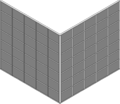
FIGURE 2.22 Curtain wall panels and mullions specified
- One condition you may notice is at the corner, where the two curtain walls meet. By default no corner mullion is specified, so the standard Rectangular Mullion : 2.5″ 5″ is used there for both overlapping ends. Corner mullions can be specified in the type properties under Border 1 or Border 2 Type.
- You can also override the mullions already placed in the model, which is more applicable at this condition since you do not want to update every border condition at every curtain wall instance for the entire model. When a curtain wall type contains defined spacing and mullions, you can still modify an individual segment by first using Unpin.
- From the 3D view hover the cursor over one of the border curtain mullions (it doesn’t matter which you choose). Press the Tab key until the mullion is highlighted; then left-click to select it. While the mullion is selected, right-click and choose Select Mullions
 On Gridline. This will select every mullion on this last grid line (Figure 2.23).
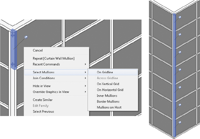
FIGURE 2.23 Mullions selected on grid line
- Notice that the Properties palette shows the rectangular mullion type as grayed out. You can’t simply swap it by default, because the type properties of the curtain wall define this type. In order to override the type, you need to first unpin the mullions. On the ribbon in the Modify panel click the Unpin tool.
- Every curtain wall mullion on this grid line is now unpinned (and still selected). You don’t need curtain mullions at both borders, so you can delete these. Since you unpinned them in the last step, you can simply press the Delete key.
- Repeat step 6 to select the remaining border mullions along the grid line. Then use the Unpin tool again. For these you want to change the curtain mullion type from the Type Selector. Change the curtain wall mullions to L Corner Mullion : 5″ 5″ Corner. Now the corner condition should look similar to the one in Figure 2.24.
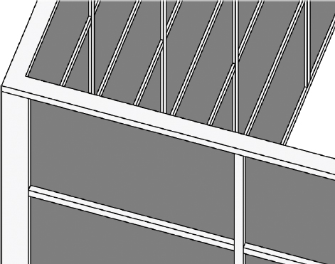
FIGURE 2.24 Curtain wall corner condition
Editing Wall Profiles
Basic, stacked, and curtain walls can have the standard rectangular shape modified to a custom shape using the Edit Profile tool. This tool is available on the ribbon after one wall is selected (it will be disabled if more than one wall is selected). When Edit Profile is activated (Figure 2.25), you can modify the rectangular profile of the wall by adding or modifying the existing sketch lines. Additionally, any closed-loop sketch lines you add in the interior will be considered openings when you click Finish Edit Mode.
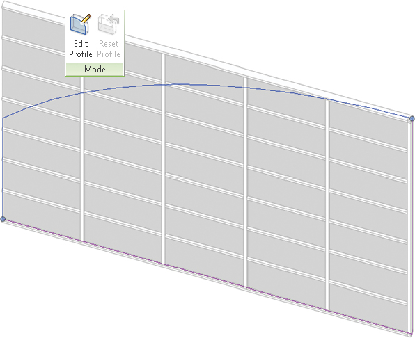
FIGURE 2.25 Edit wall profile
Embedding Curtain Walls
Curtain walls can also be embedded in walls. This may be useful for a custom storefront or similar conditions where you want the curtain wall to be hosted in a basic or stacked wall and the wall opening to be cut out automatically.
The objective of the following exercise is to add a curtain wall embedded in a basic wall. For the second portion of the exercise you will edit the embedded curtain wall profile to customize the shape.
Exercise 2.9: Embed and Edit Curtain Wall Profile
To begin, open the book’s web page at www.sybex.com/go/revit2015essentials, download the files for Chapter 2, and open the file c02-ex-2.9.start.rvt.
- The starting file should open to the Level 1 view. In this view there is a single basic brick wall.
- From the Level 1 view, start the Wall tool and change the wall type to Curtain Wall : Storefront using the Type Selector.
- Click Edit Type, and locate the Automatically Embed parameter. Confirm that it is checked (it should be by default). This parameter controls whether the curtain wall will automatically embed itself into a host wall.
- Click OK to close the Type Properties dialog. Click anywhere over the brick wall in the Level 1 view. Click the second point 20′-0″ from the first to add the curtain wall. Because Automatically Embed is checked, the curtain wall will be associated with the brick wall and the opening will be cut out of the wall.
- Open the South Elevation view. Select the curtain wall, and from the Properties palette change the Base Offset parameter to 2′-0″ (610 mm). Next, change the Unconnected Height parameter to 10′-0″ (3050 mm) (Figure 2.26).
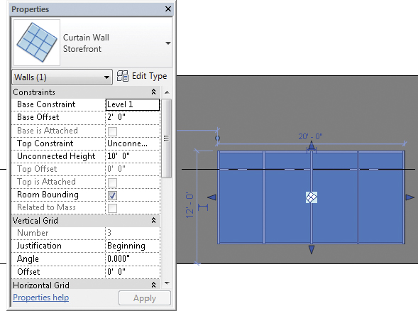
FIGURE 2.26 Curtain wall selected in wall
- While still in the South Elevation view, select the embedded curtain wall. Click Edit Profile on the ribbon to enter sketch mode.
- Select the top sketch line and press the Delete key to remove it. Then add a new sketch line, using the Start-End-Radius Arc draw tool. Click Finish Edit Mode to complete the sketch and update the curtain wall. Revit Architecture may warn you that some of the mullions in the original system can’t be created. This is fine, because some of the mullions are outside the sketch area. Click Delete Element(s) to continue (Figure 2.27).
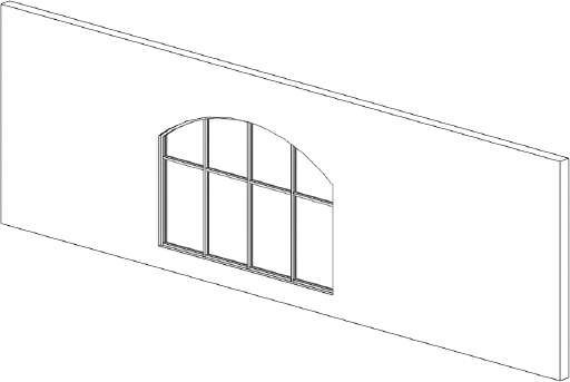
FIGURE 2.27 Curtain wall elevation view complete
The host wall will update around the embedded curtain wall to match the new profile defining the boundary condition.
Curtain Panels
Curtain panels are defined as part of the curtain wall type properties. Like the other curtain wall components, they can also be assigned on an instance basis or unpinned and changed to another infill type. A curtain panel can be a curtain panel family, a basic or stacked wall type, or another curtain wall.
Adding and Removing Grids and Mullions
So far in this chapter you have manually added curtain grids and curtain wall mullions, as well as defined the location for grid lines in the type properties. A typical curtain wall type in your project may have the majority of the grid spacing predefined by the type properties. However, you can still add or remove grid lines.
The objective of the following exercise is to manually add additional grid lines and curtain mullions to a curtain wall driven by type properties. In addition, you will remove some of the existing curtain grids to create a larger panel infill.
Then you will continue with a second exercise to modify some of the existing curtain panel instances in the curtain wall. As part of this exercise you will focus on adding a curtain panel door to the area where you removed grids and mullions.
Exercise 2.10: Add and Remove Curtain Grids and Mullions
To begin, open the book’s web page at www.sybex.com/go/revit2015essentials, download the files for Chapter 2, and open the file c02-ex-2.10.start.rvt. This file will be used for this and the following exercise.
- The starting file should open to the default 3D view. The curtain wall type Storefront - Door contains type properties for grid distances and mullion types.
- Move the cursor over one of the vertical red mullions (colored for exercise identification), and press the Tab key until the curtain grid is highlighted.
- On the ribbon notice that the Add/Remove Segments tool is now available. This tool appears only when curtain grids are selected. Click Add/Remove Segments and click the cursor over one of the red mullions. It should remove the curtain grid as well as the curtain mullion since it is hosted on the grid.
- The tool stays active so you can click the other vertical red curtain mullion to remove it. Repeat the steps to remove the remaining red horizontal curtain mullion, and you will end up with one panel, as highlighted in Figure 2.28.
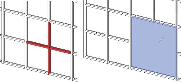
FIGURE 2.28 Removed curtain wall grids and mullions
- You can also add curtain grids and mullions in addition to those defined in the type properties. Select the Curtain Grid tool from the Build panel on the Architecture tab of the ribbon. Change the Placement option to One Segment.
- Add four vertical grid lines centered on the remaining lower curtain panels at 1′-8″ on each side. Notice that the rectangular mullions are automatically added, since the curtain wall type properties have this type specified for the Interior Type.
- Select the four new vertical mullions (use the Ctrl key to add them to the same selection set) and use the Unpin tool. While they’re still selected, change the curtain wall mullion to the 1″ Square type from the Type Selector (Figure 2.29).
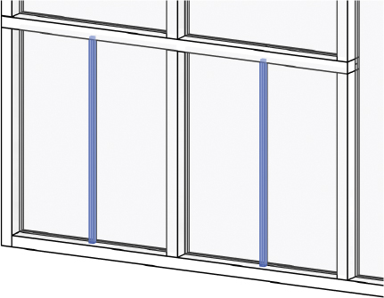
FIGURE 2.29 New grids and mullions
- Next, select the perpendicular curtain mullions above and below the new 1″ Square mullions (use the Ctrl key to add multiple items to the same selection set), and on the Mullion panel on the ribbon click Make Continuous (or click the Toggle Mullion Join symbol shown in Figure 2.30). This will toggle the mullion join at each location. The final model should look similar to Figure 2.30.
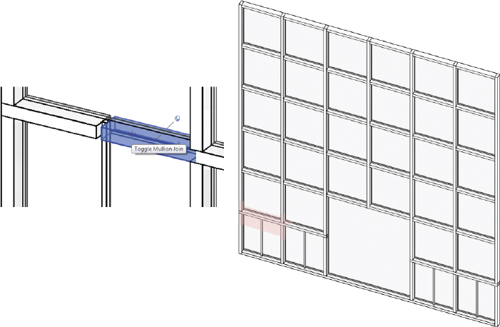
FIGURE 2.30 Finished mullions
Exercise 2.11: Customize Curtain Panels
To begin, open the book’s web page at www.sybex.com/go/revit2015essentials, download the files for Chapter 2, and open the file c02-ex-2.11.start.rvt.
- The starting file should open to the default 3D view. Select the lower eight curtain panels and click the Unpin tool. Change the curtain panel from System Panel Glazed to System Panel Solid.
- Next, you want to add a door to the curtain wall in the largest panel. Select the large System Panel Glazed panel in the center and click Unpin. Change the panel to the Curtain Wall Dbl Glass panel from the Type Selector (Figure 2.31).

FIGURE 2.31 Curtain wall door condition
- After adding the door, select the lower vertical curtain wall mullions on either side of the door (there are two mullions on each side) and toggle the mullion join to Make Continuous. This will extend the curtain mullions to the base of the curtain wall (first image in Figure 2.32).
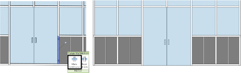
FIGURE 2.32 Final curtain wall
- Next, remove the rectangular curtain wall mullions directly under the Curtain Wall Dbl Glass panel. Select both pinned curtain wall mullions (in the same selection set) and use the Unpin tool. Once they’re unpinned, you can press the Delete key to remove the curtain mullions (second image in Figure 2.32).
- Notice that the curtain panel door adjusts to fill in the additional space after the mullions are deleted. If at any point you need to revert panel or mullion overrides, using the Pin tool will switch them back to the type defined in the curtain wall type properties.