Chapter 4
Stairs, Ramps, and Railings
Autodesk® Revit® Architecture software contains powerful tools for creating stairs, railings, and ramps. These elements are created and controlled with separate tools, which we will discuss and utilize in this chapter. In addition, these separate elements can interact with each other to form more complex systems, which we will also cover during the exercises in this chapter.
In this chapter, you’ll learn to:
- Create and modify railings
- Create stairs by component
- Create stairs by sketch
- Customize stair landings
- Create multistory stairs
- Create and customize ramps
Creating a Generic Railing
Stairs contain numerous parameters, but not all of the parameter controls are equally important during the design process. Design is often about the intent of what something is as well as where it is meant to go. Once the intent is resolved, it’s necessary to go back and revise the specifics of how something will be carefully assembled or to add additional detail when known.
Because the tools for railings, stairs, and ramps are somewhat separate, you’ll begin the exercises by first creating a simplified railing. This way, when you create a series of stair configurations, you’ll have a new, default railing to apply to each of them.
In the following exercise you will create a railing and edit the various properties and components that make up the railing tool.
Exercise 4.1: Create a Generic Railing
To begin, go to the book’s web page at www.sybex.com/go/revit2015essentials, download the files for Chapter 4, and open the file c04-ex-4.1start.rvt.
- Open the default 3D view by selecting the small house icon on the Quick Access toolbar (QAT)
 . Select the Architecture tab, and choose the Railing flyout from the Circulation panel. Select the Sketch Path option to enter sketch mode.
- Before you draw a railing, you’ll create a new type.
- Select Edit Type from the Properties palette, and with the Type Handrail — Rectangular current, click Duplicate in the Type Properties dialog box. Name the new railing Handrail — Design, and click OK twice to exit all the dialog boxes.
- Draw a path line 30′ (10000 mm) long.
- This line will define your railing path.
- Click Finish Edit Mode to exit the sketch, which will create the railing.
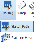
- This will be the default rail in the exercise file (Figure 4.1).
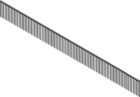
FIGURE 4.1 The default railing: Handrail — Design
- Next, you will edit some of the newly created railing properties.
- This will be the default rail in the exercise file (Figure 4.1).
- Select the railing, and choose Edit Type from the Properties palette to open the Type Properties dialog, as shown in Figure 4.2.
FIGURE 4.2 Railing type properties
- Click Edit for the Rail Structure (Non-Continuous) parameter. In the resulting dialog box click Insert. This will add another rail to your railing type. In the Name field enter Low Rail. Set the Height to 1′-0″ (300 mm) and change the Profile to Rectangular Handrail : 2″ × 2″ (Rectangular − 50 × 50 mm) (Figure 4.3). Close the dialog box by clicking OK to return to the Type Properties dialog.
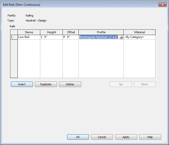
FIGURE 4.3 Edit Rails dialog box
- Locate the Top Rail group. Set the Height to 3′-6″ (1060 mm). Leave the Type as Rectangular − 2″ × 2″ (Rectangular − 50 × 50 mm). This parameter controls the top rail used in the railing.
- Next, you will modify the balusters.
- In the Type Properties dialog box, click the Edit button for the Baluster Placement parameter.
- In the resulting dialog box, find the Main Pattern panel, select the second line (Regular Baluster), and set its Baluster Family value to Baluster - Square : 1″ (Baluster - Square : 25 mm). Set the Dist. From Previous parameter to 5″ (125 mm).
- In the Posts area, set the Baluster Family value for the Start Post, Corner Post, and End Post parameters to None (as shown in Figure 4.4).
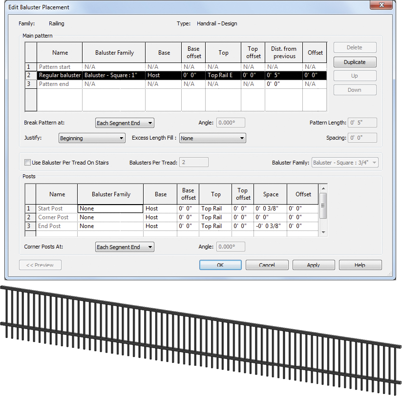
FIGURE 4.4 Baluster settings and completed railing
- Click OK to close the Edit Baluster Placement dialog box, and click OK again to close the Type Properties dialog box.
Creating Stair Configurations
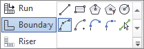
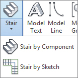 Revit Architecture has two stair tools: Stair by Component and Stair by Sketch. The tools are located on the Architecture tab on the Circulation panel. The more recent stair tool is Stair by Component. As the name suggests, this tool will help you create stairs that can be broken down into their individual components for easier manipulation. This is the default stair tool on the ribbon in Revit Architecture. The original stair tool, Stair by Sketch, is located in the Stair flyout. The majority of our exercises in this chapter will focus on the more recent Stair by Component tool.
In the following exercise you will create a straight run stair by component to familiarize yourself with the options and components of the stair.
Exercise 4.2: Create a Stair by Component
To begin, go to the book’s web page at www.sybex.com/go/revit2015essentials, download the files for Chapter 4, and open the file c04-ex-4.2start.rvt.
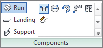
- From the Level 1 plan view, start the Stair By Component tool. The tool should default to using the Run component. Click any point to the left, and then move your cursor to the right.
- As you do, Revit Architecture tells you how many risers remain to complete a stair that starts on Level 1 and goes through Level 2 (Figure 4.5).
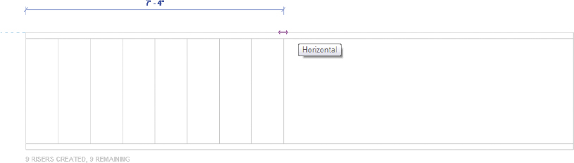
FIGURE 4.5 Risers remaining to finish stair
- As you do, Revit Architecture tells you how many risers remain to complete a stair that starts on Level 1 and goes through Level 2 (Figure 4.5).
- Click when you see the message 9 Risers Created, 9 Risers Remaining. This will complete the first run of the stair. Since you have not created enough risers to reach Level 2, you need to start another run. Move the cursor over to the right until the temporary dimension displays 5′-0″ (1525 mm). Click again to start the next run, and click to the right when you see 9 Risers Created, 0 Risers Remaining (Figure 4.6).
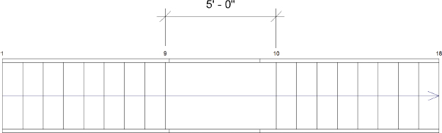
FIGURE 4.6 Component stair run with landing
- Select the Railings tool in the Tools panel of the ribbon. Specify the Handrail - Rectangular type (Figure 4.7), and click OK to close the dialog.
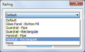
FIGURE 4.7 Specifying the railing type
- Revit Architecture will use this default handrail whenever you create this stair, until you specify another type. The railing can be edited, modified, or deleted at any time from the stair.
- Click Finish Edit Mode to complete the component stair.
- The resulting stair is shown in the default 3D view in Figure 4.8.
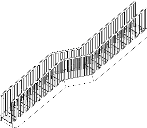
FIGURE 4.8 The resulting stair with railing
- Now you’ll create a second component stair to adjust some additional parameters.
- The resulting stair is shown in the default 3D view in Figure 4.8.
- Start the Stair By Component tool again, but before you pick a point to start the first run, choose the Location Line option from the Options Bar.
- Set the Location Line to Exterior Support: Left. This will align the outside edge of the stair with your pick points, making it easier to snap to existing geometry.
- For the start of the first run, click the endpoint of reference plane 1 where it meets the wall. Move to the right 6′-5″ (955 mm), and click again to complete this run.
- Start the second stair run using the same Location Line setting, and click at the endpoint of reference plane 2 where it meets the wall. Move down anywhere past 9′-0″ (2750 mm), and click the last point to complete the second run (Figure 4.9).
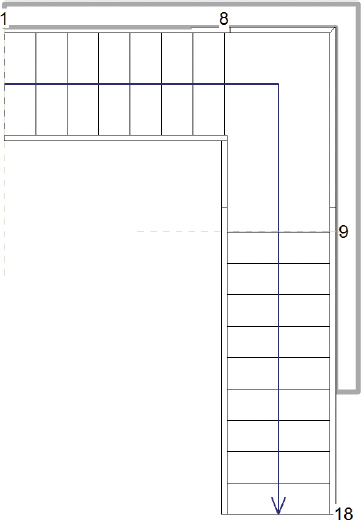
FIGURE 4.9 Second stair along wall
- One of the nice features of component stairs is the ability to dynamically change the stair using shape handles.
- Select the landing that was automatically created and notice the shape handles. Drag the landing edge shape handle down any distance to enlarge the landing. Notice that the stair run automatically moves down to reflect the new landing size.
- Click Finish Edit Mode to complete the component stair (Figure 4.10).
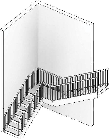
FIGURE 4.10 Completed second stair with landing
In the following exercise you will create a straight run stair by sketch to familiarize yourself with the workflow and properties of this stair type.
Exercise 4.3: Create a Stair by Sketch
To begin, go to the book’s web page at www.sybex.com/go/revit2015essentials, download the files for Chapter 4, and open the file c04-ex-4.3start.rvt.
- From the Level 1 plan view, start the Stair by Sketch tool from the Stair flyout. Click any two points from left to right (far enough apart for Revit to display 18 Risers Created). This will create an 18-riser straight stair between Level 1 and Level 2.
- Select the top boundary line and drag the end grip back two risers (Figure 4.11).
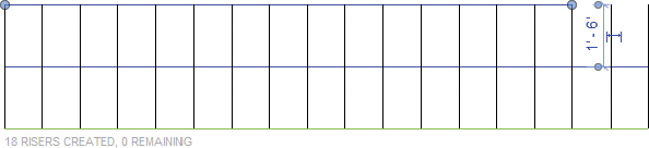
FIGURE 4.11 Sketch-based stair boundary line
- Draw a new boundary line for these two risers to create a custom condition using the Start-End-Radius Arc Draw shape.
- Using the Trim/Extend Single Element tool, extend the riser line to meet the new boundary line you added in step 3 (Figure 4.12).
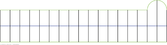
FIGURE 4.12 New boundary and riser sketch lines
- Select the lower boundary line and notice that the temporary dimension appears showing 1′-6″.
- Click the temporary dimension text and enter 2′-6″ to move the lower boundary line down.
- Notice that the riser sketch lines did not automatically move down with the boundary line.
- Use the Trim/Extend Multiple Elements tool to extend the riser lines to meet the new boundary line location (Figure 4.13).
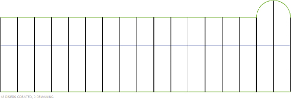
FIGURE 4.13 Updated boundary line location
- Click Edit Type to open the stair Type Properties.
- Under Risers, uncheck the End With Riser parameter and click OK to close the dialog.
- This will remove the riser that is generated at the end of the stair.
- Click Finish Edit Mode to complete the stair.
- Ignore any warnings received about actual number of risers created.
- Select the two railings that were automatically created, and swap the type in the Type Selector to Glass Panel - Bottom Fill. The completed stair is shown in Figure 4.14.
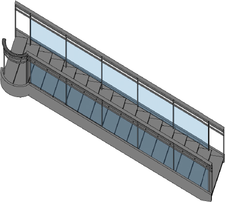
FIGURE 4.14 Completed sketch-based stair
In the following exercise you will customize an existing Stair by Component landing to reflect changes to the design.
Exercise 4.4: Customize and Create a Component Stair Landing
To begin, go to the book’s web page at www.sybex.com/go/revit2015essentials, download the files for Chapter 4, and open the file c04-ex-4.4start.rvt.
- From the Level 1 plan view, select the existing stair and click Edit Stairs to enter edit mode.
- Click to select the existing landing object.

- You want to customize the landing shape so you will need to convert the landing to a sketch.
- Click Convert To Sketch-Based on the Tools panel. Close the dialog confirming that this conversion is irreversible.
- Notice there is a new option called Edit Sketch on the same Tools panel.

- Click Edit Sketch to edit the landing boundary. Select and delete the existing landing boundary line (the longest line closest to the wall).
- Set the type of lines to Boundary in the Draw panel. Set the draw mode to Pick Lines. Set the Options Bar Offset parameter to 2″ (50 mm) so you can compensate for your support distance along the wall.
- Pick the faces of the interior wall lines to create the new landing sketch lines. Use the Trim/Extend To Corner tool to clean up the new boundary lines.
- For the last segment, at the start of the second stair run you will need to create a small sketch line with the same 2″ (50 mm) offset. This offset will accommodate the stringers that will be created around the landing.
- The final sketch is shown in Figure 4.15.
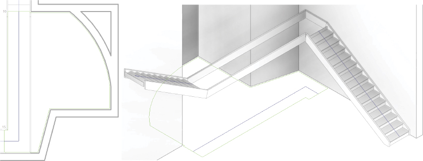
FIGURE 4.15 Revised landing sketch
- The final sketch is shown in Figure 4.15.
- Click Finish Edit Mode.
- Notice that you are still editing the component stair; you simply finished editing the landing sketch.
- While still editing the stair, add a second landing.
- On the Components panel click Landing. Choose the Create Sketch option.
- Confirm that the Properties palette Relative Height parameter is set to 15′-0″ (4570 mm). With the Draw option set to Boundary, sketch a second landing at the end of the second run, as shown in Figure 4.16.
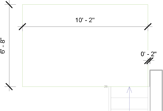
FIGURE 4.16 Revised landing sketch
- Click Finish Edit Mode to complete the new landing sketch. Click Finish Edit Mode again to complete the stair.
- The finished stair is shown in Figure 4.17.
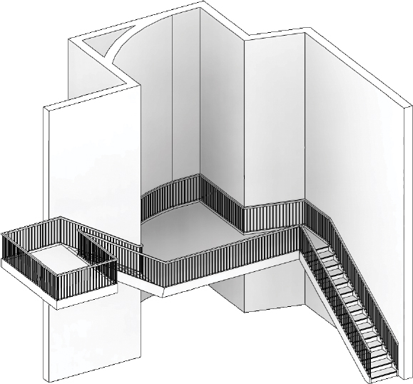
FIGURE 4.17 Complete stair with new landings
- The finished stair is shown in Figure 4.17.
In the following exercise you will update an existing stair to span multiple project levels using the Multistory Top Level instance property.
Exercise 4.5: Create a Multistory Stair
To begin, go to the book’s web page at www.sybex.com/go/revit2015essentials, download the files for Chapter 4, and open the file c04-ex-4.5start.rvt.
The example file has five project levels, and you want to repeat the existing stair between them since they are consistent level heights.
- Activate the 3D view saved in the exercise file.
- Select the stair and from the Properties palette locate the Multistory Top Level instance parameter.
- Currently it is set to None.
- Change the value to Level 5 and notice what happens (Figure 4.18).

FIGURE 4.18 Multistory stair up to Level 5
- Revit will repeat the stair up to the level you specified, including any railings that are currently attached to the stair.
- Select one of the railings and notice that all four instances of the railing are selected.
- Change the railing type to Guardrail - Pipe and notice that all four railings update to reflect the type change.
- Select the stair and click Edit Stairs to enter edit mode.
- Open the Level 1 floor plan view. Select the landing, and using the shape handles adjust it to be 2-6″ (760 mm) on each side that meets the run (Figure 4.19).
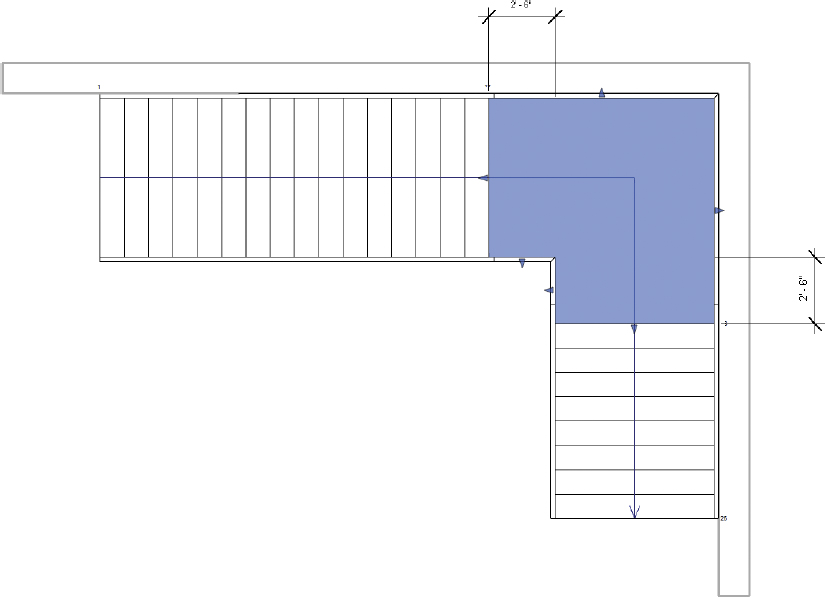
FIGURE 4.19 Landing adjustment
- Click Finish Edit Mode to return to the project.
- Open the 3D view again, and notice that every stair landing has also been updated.
- Select the stair and change the Multistory Top Level parameter to Level 4.
- The stair will update to reflect the new top-level assignment (Figure 4.20).
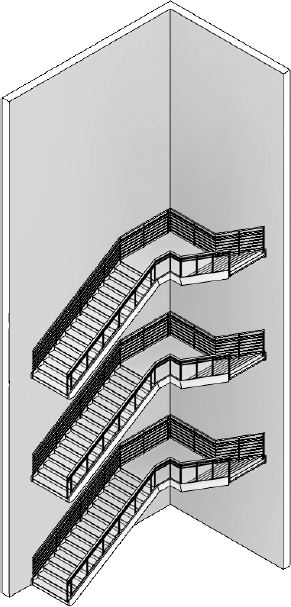
FIGURE 4.20 Complete multistory stair
- The stair will update to reflect the new top-level assignment (Figure 4.20).
In the following exercise you will create a new railing and set the host to use an existing stair.
Exercise 4.6: Host a Railing to a Stair
To begin, go to the book’s web page at www.sybex.com/go/revit2015essentials, download the files for Chapter 4, and open the file c04-ex-4.6start.rvt.
- From the Level 1 plan view, click the Railing flyout and choose Sketch Path.
- Using the Pick Lines draw tool, select the inner line for each of the three stringers (see the sketch in Figure 4.21).
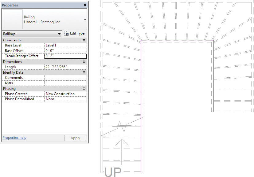
FIGURE 4.21 First sketch and Tread/Stringer Offset
- Then, from the Properties palette, set the Tread/Stringer Offset instance parameter to 2″ (50 mm).
- This will allow you to pick a specific reference but still assign a set value to move the railing to (Figure 4.21).
- Click Finish Edit Mode to complete the railing.
- Create another railing using the same steps but for the opposite outside three stringers. Instead of using 2″ (50 mm) for the Tread/Stringer Offset use -2″ (-50 mm) (Figure 4.22).
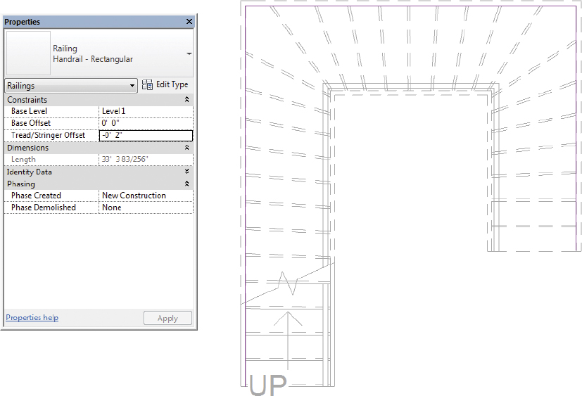
FIGURE 4.22 Second sketch and Tread/Stringer Offset
- Click Finish Edit Mode to complete the sketch.
- Open the default 3D view and note that the railings are not yet hosted to the stair but are instead hosted to Level 1.
- Select one of the railings and click Pick New Host on the Tools panel.

- Click the stair; this will change the railing host from Level 1 to instead attach and follow the geometry of the stair.
- Click Pick New Host for the second railing to complete the new railing host (Figure 4.23).
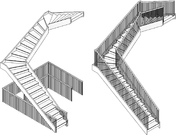
FIGURE 4.23 Railing before and after new host
In the following exercise you will customize an existing railing top rail to allow for a custom termination condition.
Exercise 4.7: Edit Railing Top Rail and Slope
To begin, go to the book’s web page at www.sybex.com/go/revit2015essentials, download the files for Chapter 4, and open the file c04-ex-4.7start.rvt.
- Open the example file to the 3D view.
- Move the cursor over the top rectangular rail and press the Tab key once. The top rail should be highlighted.

- Click to select the top rail (Figure 4.24).
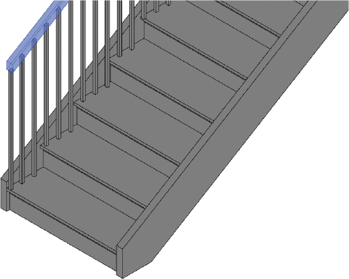
FIGURE 4.24 Select the top rail.
- Once it’s selected, click Edit Rail on the Continuous Rail panel.
- Click Edit Path and choose the Line Draw shape.
- Draw a custom path for the top rail starting at the endpoint of the existing path, similar to Figure 4.25.

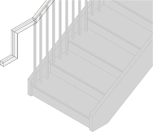
FIGURE 4.25 Updated top rail path
- Click Finish Edit Mode twice to finish editing the top rail and return to the project.
- Next, you’ll correct the railing condition at the top of the landing to match the flat slope.
- Open the Level 1 floor plan view.

- Select the railing and click Edit Path to return to sketch mode.
- Use the Modify panel’s Split Element tool
 to split the railing path at the edge of the landing (Figure 4.26).

FIGURE 4.26 Split railing path sketch
- Press the Esc key twice, and select the split railing sketch path over the landing.
- On the Options Bar change the Slope to Flat.
- Click Finish Edit Mode to exit the railing sketch.
- Open the default 3D view, and notice that the railing condition is now flat over the landing.
- You can use the Slope controls for railing conditions when you need to override how the default slope will be calculated. The completed railing is shown in Figure 4.27.
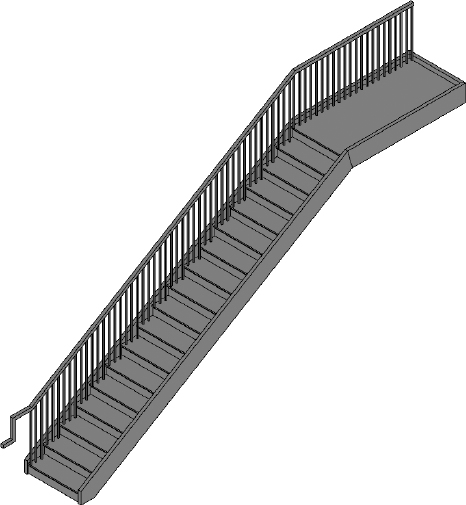
FIGURE 4.27 Completed railing
- You can use the Slope controls for railing conditions when you need to override how the default slope will be calculated. The completed railing is shown in Figure 4.27.
Designing Ramps
Now that you’re familiar with designing a number of stair configurations, ramps should come easily since they are based on the Stair by Sketch tool. It’s the same basic process of sketching a desired shape and then completing the sketch, with one major difference: far more frequent landings and a shallower slope.
You access the Ramp tool on the Circulation panel on the Architecture tab. Keep in mind that ramps have different constraints than stairs based on slope and length. Understand that the maximum length of a ramp in one section is 30′-0″ (9000 mm) with a 1:12 slope (8 percent). These parameters can be changed, but by default they correlate to common code requirements.
In the following exercise you will create a straight run ramp between Level 1 and Level 2. Because you’re traversing Level 1 to Level 2 (and they are 10′ [3000 mm] apart), this will require a ramp length of 120′ (36,600 mm) at a maximum 1:12 slope, not including landings.
Exercise 4.8: Create a Ramp and Edit the Boundary
To begin, go to the book’s web page at www.sybex.com/go/revit2015essentials, download the files for Chapter 4, and open the file c04-ex-4.8start.rvt.
- Open the example file to the Level 1 view.
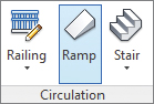
- Select the Architecture tab, and choose the Ramp tool from the Circulation panel.
- In the Properties palette set the Ramp Type to Ramp 1; the Base Level is Level 1 and the Top Level is Level 2.
- Using the Run Draw tool, add straight runs similar to Figure 4.28.
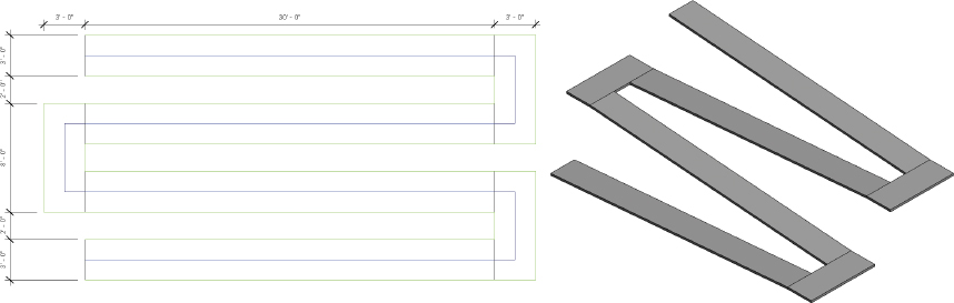
FIGURE 4.28 Straight runs of ramps
- To get all the landings and ramps into the right location, select the boundary and riser lines after creation and move them using the Move tool on the Modify panel.
- The ramp should look similar to the image in Figure 4.28.
- Click Railing on the Tools panel, and specify the Handrail - Rectangular railing. Click OK to close the dialog.
- Click Finish Edit Mode to complete the sketch. Open the default 3D view; you should see a similar ramp to Figure 4.29.
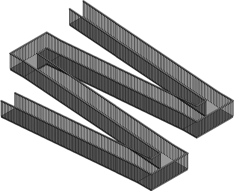
FIGURE 4.29 Ramp runs with associated railings
- Return to the Level 1 view, select the ramp, and click Edit Sketch.
- Delete the three green boundary lines that represent the outside edges of the landings, as shown in Figure 4.30.
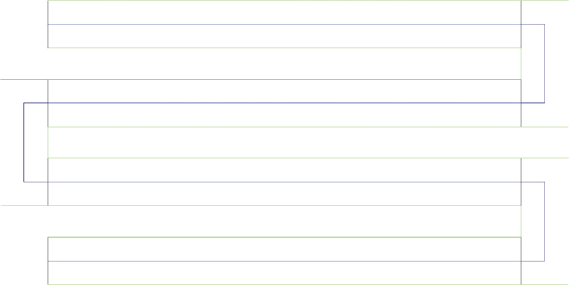
FIGURE 4.30 The modified ramp in plan with removed exterior boundary edges
- Select the Boundary tool on the Draw palette, and then choose the Tangent End Arc tool on the Draw panel.
- Create the new boundaries shown in Figure 4.31 by picking one boundary edge and then the other.
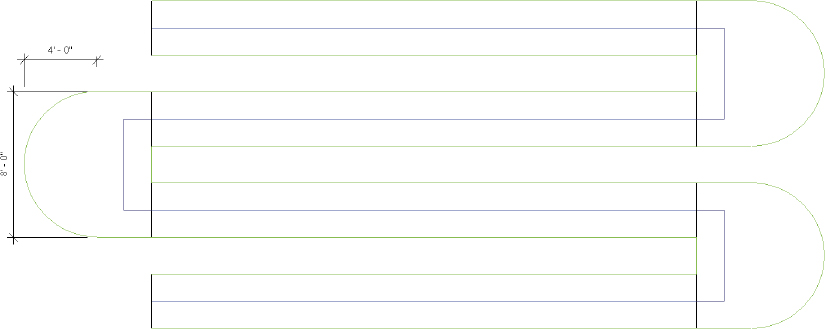
FIGURE 4.31 Modified ramp with curved boundary
- Click Edit Type to open the ramp type properties.
- Under Other, set Shape to Solid. Click OK to close the dialog.
- This will create a solid slab ramp instead of maintaining a consistent thickness value.
- Click Finish Edit Mode to complete the sketch.
- Revit Architecture has already modified the railings to accommodate the new boundary (Figure 4.32).
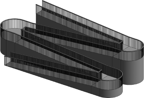
FIGURE 4.32 Completed ramp in 3D
- Revit Architecture has already modified the railings to accommodate the new boundary (Figure 4.32).
The end exercise file has both ramp shapes, included as two separate ramps, for reference.