Chapter 5
Adding Families
What is a family in the Autodesk® Revit® Architecture software? In the simplest terms, a family can be thought of as repeatable geometry for use in a project. You will now take a step back from the modeling exercises in the previous chapters to develop a better understanding of the basic building blocks that make up a Revit Architecture project.
In this chapter, you’ll learn to:
- View and modify the family category
- Work with and load system families
- Work with and load component families
- Work with hosted families
- Work with face-based families
- Create an in-place family
- Find and load family content into your project
Understanding the Model Hierarchy
In Chapters 2 (“Walls and Curtain Walls”), 3 (“Floors, Roofs, and Ceilings”), and 4 (“Stairs, Ramps, and Railings”), you learned about some basic model elements such as walls, floors, and roofs. These types of objects are known as system families in the Revit Architecture software. To better explain what a family is and how it relates to your workflow, let’s explore how data is organized in the Revit Architecture platform.
One of the unique characteristics of the program is its inherent model hierarchy. In a simple description, this hierarchy can be expressed as (from broad to specific) project, category, family, type, and instance.
Project This is the overall container for the model geometry and information.
Category This is the structure of the content that will be placed in the project. This is how the Revit Architecture software ensures consistency and manages the behavior of elements such as how a door interacts with a wall. You also use categories to manage graphic display and visibility of elements.
Family Similar to blocks in AutoCAD, families are the basis of geometry you create in a Revit Architecture project.
Type This is a repeatable variation within a family. For example, each type in a six-panel door family could have size or material variations without duplicating geometry. For example, the door panel extrusion could adjust size based on the door type width.
Instance This is an actual element you place in the project model. For example, door 607 may be the 25th instance you’ve placed in the project of the 36 × 80 Wood (0915 × 2032 mm) type of the 6-panel door family.
In the following exercise, you will modify some display properties throughout the entire project using Object Styles. Then you will change the settings of one view using the Visibility/Graphic Overrides dialog. Lastly you will change the settings of one instance using Override Graphics in View By Element.
Exercise 5.1: Creating a Model Hierarchy
To begin, go to the book’s web page at www.sybex.com/go/revit2015essentials, download the files for Chapter 5, and open the file c05-ex-5.1start.rvt.
- Open the Level 1 view and click the Manage tab; then choose Object Styles from the Settings panel.
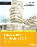
- The categories you see in the Object Styles dialog box (Figure 5.1) are those that are established by the software and cannot be changed. You can use these categories to modify the default display characteristics of element categories in your project.
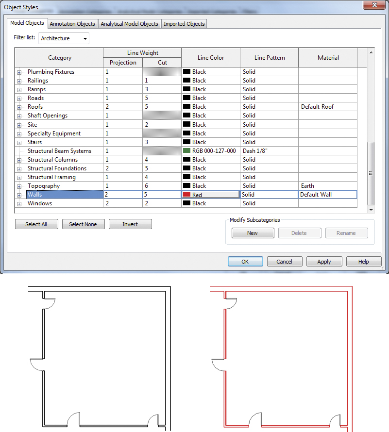
FIGURE 5.1 Object Styles Walls Line Color
- The categories you see in the Object Styles dialog box (Figure 5.1) are those that are established by the software and cannot be changed. You can use these categories to modify the default display characteristics of element categories in your project.
- On the Model Objects tab, find the Walls category, and click in the Line Color field to open the Color dialog box. Set the line color to Red, and click OK.
- Click OK to close the Object Styles dialog box. All walls in every project view are now displayed with red lines instead of black.
- Press VG on your keyboard (this is the keyboard shortcut for the Visibility/Graphic Overrides command, located on the View tab of the ribbon).
- You can also access this dialog from the Properties palette for each view using the Visibility/Graphic Overrides Edit button.
- In the Visibility/Graphic Overrides dialog box on the Model Categories tab, find the Doors category, and place a check in the Halftone column.
- While still in the Visibility/Graphic Overrides dialog, Model Categories tab, uncheck Visibility for the Furniture category. This will turn off the display of all furniture category elements in this view only.
- Click OK to close the dialog box. Doors are now displayed in the Level 1 floor plan as halftone, and furniture is no longer visible.
- Select several of the Level 1 view doors, right-click, and select Override Graphics In View
 By Element.
 - Uncheck the box for Visible, and click OK to close the dialog box.
- The door instances are no longer visible in the Level 1 floor plan, yet other door instances are still visible in this and other views (Figure 5.2).
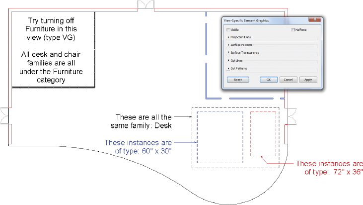
FIGURE 5.2 Completed project, view, and element overrides
- The door instances are no longer visible in the Level 1 floor plan, yet other door instances are still visible in this and other views (Figure 5.2).
In the preceding exercise, you made changes to objects on three levels. Object Styles is a project-wide change for the selected category. The Visibility/Graphic Overrides dialog is a view-specific override for the selected category. Override Graphics In View ![]() By Element is a view-specific override for an instance of the selected category.
By Element is a view-specific override for an instance of the selected category.
Revit Architecture uses three types of families: system, component, and in-place families. System and in-place families exist only in the project file, whereas component families are created and stored as RFA files outside the project environment. In-place families should be used only for unique, one-of-a-kind objects for which you require nearby geometry as a reference to design.
We will start by exploring system families because they reside directly in the project. Then we will further explore component and in-place families later in this chapter.
Working with System Families
The first type of family you need to understand is the system family. The best way to characterize system families is to consider them the hosts for other types of geometry. 3D elements such as walls, floors, ceilings, and roofs allow other elements such as doors and windows to exist on them or in them. Other 3D elements, such as stairs and railings, are also system families.
System families are unique in that they create geometry by using a set of rules applied to guiding geometry. If you think about a simple wall, for example, its thickness is defined by a series of structural layers (framing, sheathing, and finishes), its length is expressed by a linear path, and its height is established by some set of horizontal boundaries (either a datum or another element like a roof). As another example, a floor’s thickness is defined by a series of structural layers, its vertical location is determined by a datum (level), and its boundary extents are defined by a series of lines. In the project, these rules are the instance and type properties.
Some system families are 2D. These types of system families include text, dimensions, and filled regions. Although the 2D variety of families are still considered system families, we think they are better referred to as project settings to avoid confusing them with the more common understanding of families.
Loading System Families
Because system families exist only in the project environment, there are only a few ways you can load them between projects. The first method is to use the Transfer Project Standards command. This method transfers all the families and types in a selected category between projects.
A more informal method of transferring system families is to use the Windows Clipboard functions and copy/paste content between projects. This method is useful if you want to load a limited number of specific families into your active project.
Although it isn’t an active loading method, the final technique to manage system families is to include them in your project templates. After you establish a level of comfort with working in Revit Architecture, you will begin to customize your own templates, thus minimizing the amount of loading required throughout the design and production process.
In the following exercise, you will explore copying wall families between two projects using the Transfer Project Standards tool.
Exercise 5.2: Transfer Project Standards
To begin, go to the book’s web page at www.sybex.com/go/revit2015essentials, download the files for Chapter 5, and open the file c05-ex-5.2start.rvt.
- In the exercise project file there are some custom wall types you want to copy into a new project (TypeA.1, TypeB.3, and TypeC.4). Keep the
c05-ex-5.2start.rvtproject file open. - Create a new project file using the default template.
- In the new project, go to the Manage tab’s Settings panel, and click Transfer Project Standards.
- In the Select Items To Copy dialog box, click the Check None button, and then select Wall Types from the list, as shown in Figure 5.3.
FIGURE 5.3 Selecting Wall Types to transfer between projects
- Confirm that Copy from lists
c05-ex-5.2start.rvt.- This is especially important to verify if you have more than two project files open to ensure you copy from the expected file (Figure 5.3).
- Click OK. Choose New Only, if prompted, to close the dialog box and complete the transfer. New Only will only copy walls that are not currently in the new project (and avoid overwriting types with the same name).
- Start the Wall tool from the Architecture tab in the new project, and locate the transferred wall types TypeA.1, TypeB.3, and TypeC.4.
- Create some wall segments with these new types.
In the following exercise, you will place wall families through various methods.
Exercise 5.3: Place System Families
To begin, go to the book’s web page at www.sybex.com/go/revit2015essentials, download the files for Chapter 5, and open the file c05-ex-5.3start.rvt.
- Open the Level 1 view. In the Project Browser, toward the bottom of the list, click the + to expand the Families heading.
- Expand the Walls category, and you see three values (Basic Wall, Curtain Wall, and Stacked Wall). These are the three families of walls contained within a project.
- Expand the Basic Wall list, and you see all the wall types in the Basic Wall family.
- Using the cursor, left-click+drag the wall type named TypeB.3 from the Project Browser into the Level 1 view.
- Notice how it automatically starts the Wall tool using the type you dragged in.
- Draw some wall segments in the view and press the Esc key to exit the command.
- Next, in the Project Browser right-click the same wall type and select Create Instance. Notice that this does the same thing.
- Select one of the walls you added in the Level 1 view and right-click Create Similar (Figure 5.4). This is another way to create a new instance of the same wall type you selected in the view.
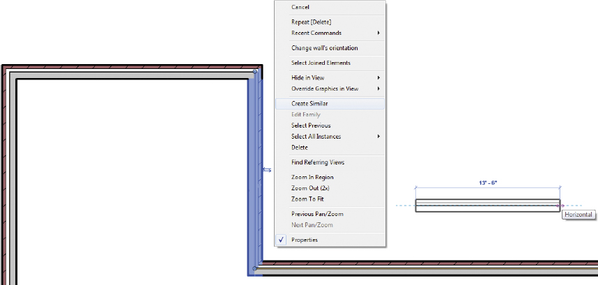
FIGURE 5.4 Using Create Similar to place walls
There is another method to create a wall. Since you just used the Wall tool in step 7, you can access it by right-clicking Recent Commands. You can do this with nothing selected in the view to start creating another wall. And it should use the last wall type you placed in the view.
Working with Component Families
The second type of family you need to understand is the component family. These types of families live outside the project environment in RFA files and consist of everything from doors and windows to furniture and equipment. You might think of component families as anything that would be manufactured away from the job site and delivered for installation. This is in contrast to the aforementioned system families, which can be thought of as anything that is assembled at the job site.
Similar to system families, there are also 2D view—specific versions of component families including tags, symbols, detail components, and profiles:
Tags These component families are scale-dependent annotations that contain what are known as labels (the equivalent of block attributes in Autodesk® AutoCAD® software). Labels are special text elements that report information from model elements. Remember, the information (number, name, keynote, and so on) is stored in the component—not in the tag. Tags are attached to system or component families in the project.
Symbols (Generic Annotations) These component families are scale-dependent annotations that can also contain labels (similar to a tag). The main differentiator between symbols and tags is that symbols can be placed freely and do not need a host in the project. Symbols can also be loaded and used in other families such as tags.
Detail Components Used in drafting views or to embellish model views, detail components can be used as a more intelligent alternative to simple drafting lines. These components can be tagged or keynoted as if they were model components. You will find much more information on detailing in Chapter 11, “Details and Annotations.”
Profiles Profile families consist of a simple outline of a shape. They are used only in conjunction with other system families such as railings, wall sweeps, and curtain-wall mullions. After you create a profile family, it must be loaded into a project and then associated with a respective system family. A profile’s function must be defined in the family parameters (Figure 5.5).

FIGURE 5.5 Defining a profile’s function
In the following exercise you will examine the family’s category. Then you will explore various methods to load families into your project.
Exercise 5.4: Create a New Family and Load It into a Project
A family’s initial category is determined by the template used when the family is created. For this exercise you will be creating a new family using one of the default templates, so no exercise file is required.
- From the Application button, click New Family. The New Family — Select Template File dialog box opens (Figure 5.6).
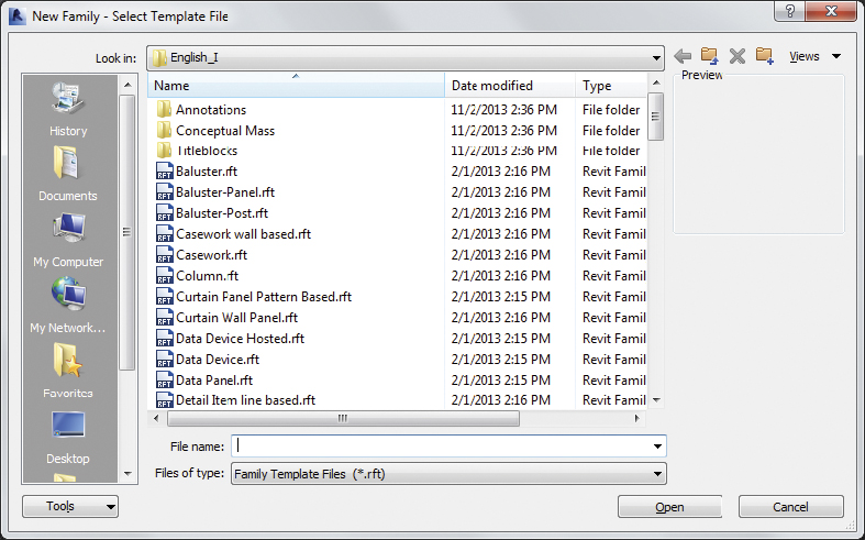
FIGURE 5.6 Selecting a family template
- The list of family templates is consistent with the list of categories you saw in the project environment (Object Styles, Visibility/Graphic Overrides). Each of the available family templates is preconfigured for a specific category in terms of properties, basic materials, and reference planes.
- Select
Plumbing Fixture.rft(Metric Plumbing Fixture.rft), and click Open.- The Revit Architecture user interface changes slightly to what is known as the Family Editor (keep in mind that you are still within the main Revit Architecture application).
- Go to the Create tab’s Properties panel, and click the Family Category and Parameters button.
- The Family Category and Parameters dialog box opens (Figure 5.7); it shows the category to which the family is assigned (Plumbing Fixtures).
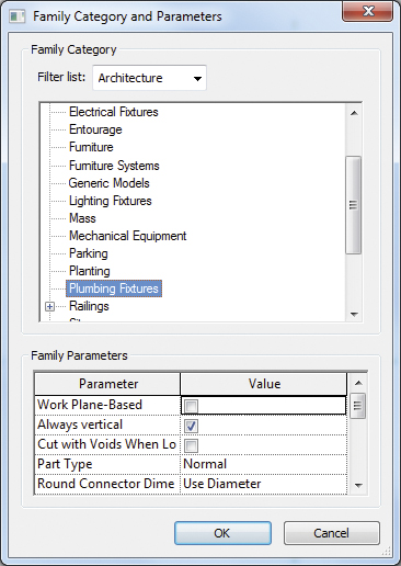
FIGURE 5.7 Viewing the family category and parameters
- The Family Category and Parameters dialog box opens (Figure 5.7); it shows the category to which the family is assigned (Plumbing Fixtures).
- Click OK to close the dialog.
- Next, you want to practice saving this family and loading it into a project (let’s pretend for now that you added geometry in the Plumbing Fixtures family.
- From the Application button, click Save As Family. Call the family
Plumbing Test(notice that the file extension is now.rfa).- When the save completes, you’ll load this family into a new project.
- Create a new project with the default template. Then navigate back to the
Plumbing Testfamily. From any tab in the ribbon click Load Into Project.
- If you have more than one project file open, Revit will prompt you for which one to load. If you have one project open, Revit will switch you to the project and immediately start placing the family you just loaded. Notice how Place Component is now active and the
Plumbing Testfamily is current.
- If you have more than one project file open, Revit will prompt you for which one to load. If you have one project open, Revit will switch you to the project and immediately start placing the family you just loaded. Notice how Place Component is now active and the
- Press the Esc key to cancel placing the family.
- Another method to load families is to use the Load Family tool located on the Insert tab’s Load From Library panel.
- Click the Load Family tool to open the Load Family dialog box, which should open to the family library location.
- Open the
Doorsfolder. Notice that you can select multiple families to load at the same time by holding down the Shift or Ctrl key. - Select several families and click Open (Figure 5.8).

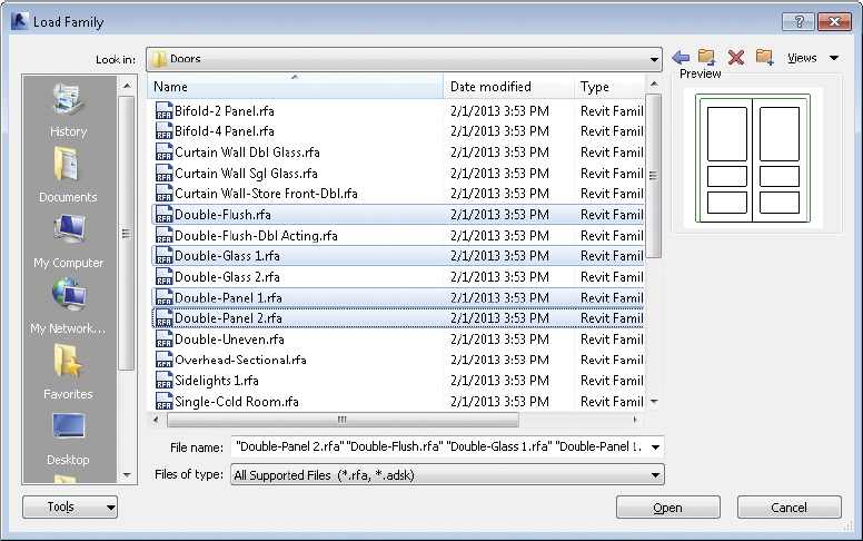
FIGURE 5.8 Selecting multiple files when loading families
Employing Hosted Families
For 3D component families, one key distinction you should understand is whether a family is hosted. How do you know whether a family is hosted or unhosted? A simple way to find out is to observe the cursor when a component command is activated and you attempt to place a family. For a hosted family, the cursor will change ![]() to indicate that you cannot place the family unless you are clicking over a suitable host.
to indicate that you cannot place the family unless you are clicking over a suitable host.
The main limitation to a hosted element is that it cannot exist without its host. Certain component families, such as doors and windows, must be hosted because their behavior dictates that they cut their host geometry when placed. For example, you can see this when creating a new door or window family. Notice when opening the family that there is also a system family wall, which serves as the host. Other components, such as furniture, plumbing, and light fixtures, may not need to be modeled as hosted components. These types of objects are placed in a model and almost always maintain a reference to the level on which they were placed.
A slightly different version of a hosted family is known as a face-based family. These types of families can be placed on virtually any surface or work plane, but they don’t suffer the same limitations as hosted families. Face-based families can exist without a host element even after a host is deleted. When the family is initially created, the family template used will determine the category of the family and whether it is hosted, not hosted, or face-based.
In the following exercise you will work with hosted and unhosted families to explore the default behaviors. In the second exercise you will place and modify face-based families, which are another type of hosted family.
Exercise 5.5: Work with Hosted Families
To begin, go to the book’s web page at www.sybex.com/go/revit2015essentials, download the files for Chapter 5, and open the file c05-ex-5.5start.rvt. The example file should open to the Level 1 view.
- On the Architecture tab, select the Place A Component tool, and then click Load Family on the ribbon. Navigate to the location of the downloaded exercise family files, and load the
ex-5.5hosted.rfafile. - In the room at the upper right in the layout, place five instances of the
ex-5.5hosted.rfafamily on the horizontal partition wall (Figure 5.9). Space the first and last fixtures roughly 3′-0″ off the wall ends, and set the other three equally spaced. Notice that you can place these components only on a wall.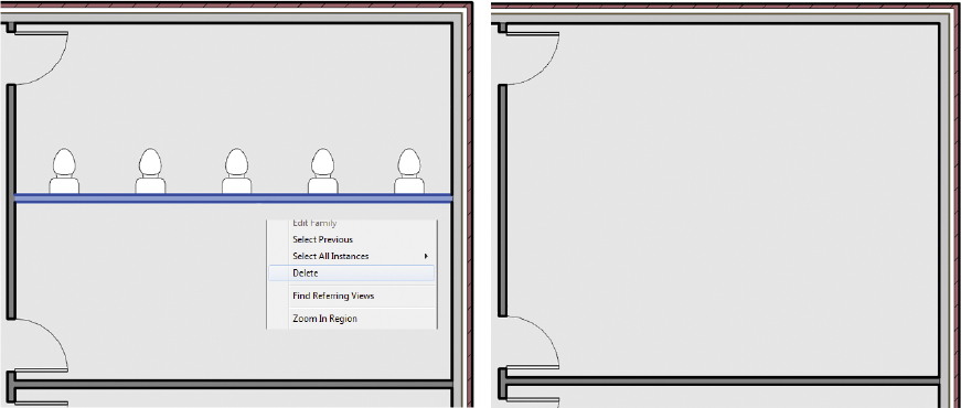
FIGURE 5.9 Placing hosted components and deleting the wall
- Click the Modify button on the ribbon or press the Esc key to exit the command, and then move the host partition wall up and down. Observe how the components move with the wall.
- Delete the partition wall where you placed the components in step 2. The hosted plumbing fixtures are automatically deleted when the wall segment is deleted (indicated in Figure 5.9). Use the Undo command to restore the wall and hosted fixtures.
- Next, you will use the unhosted version of the family. Start the Place A Component command again, and click the Load Family button. Navigate to the
c05-ex-5.5unhosted.rfafile, and load it into your project. - Place five instances of the
c05-ex-5.5unhosted.rfafamily along the opposite side of the same partition wall, as shown in Figure 5.10. You can use the Align tool after placement to easily align them to the wall and the opposite side elements.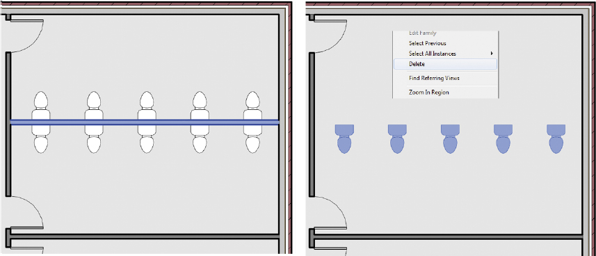
FIGURE 5.10 Placing unhosted components in a model
- Select the five
c05-ex-5.5unhosted.rfafamilies, and go to the Options Bar and select the Moves With Nearby Elements setting. - Move the host partition wall up and down, and observe that the fixtures display the same behavior as the hosted versions.
- Delete the partition wall (as indicated in Figure 5.10). The unhosted fixtures remain (but the hosted fixtures are deleted again).
You can easily move selected components from one level to another by changing the Level parameter in the Properties palette (Figure 5.11).
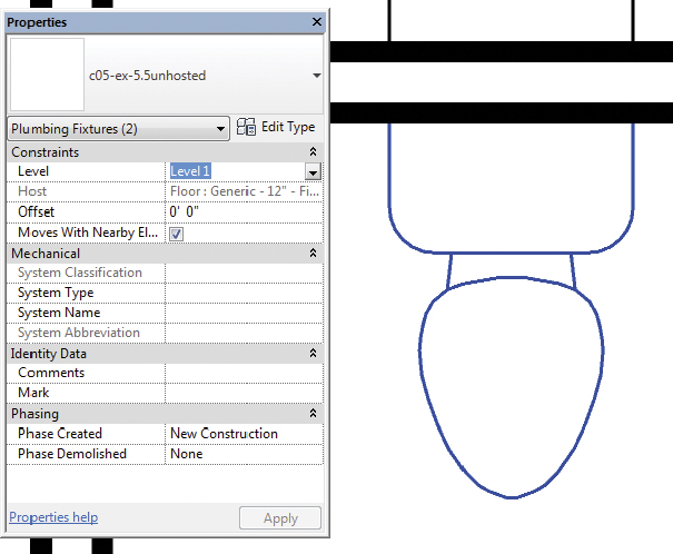
FIGURE 5.11 Adjusting an object’s Level property
Exercise 5.6: Place Face-Based Families
To begin, go to the book’s web page at www.sybex.com/go/revit2015essentials, download the files for Chapter 5, and open the file c05-ex-5.6start.rvt.
- The example project should open to the default 3D view, and you see the extents of the sample project with multiple roofs.
- The
c05-ex-6.Facebased.rfageneric model family is already loaded in yourc05-ex-5.6start.rvtproject. There is one instance placed on the roof (Figure 5.12). If needed it can be located from the Project Browser under Families Generic Models c05-ex-6.Facebased. This family was originally created with the family templateGeneric Model face based.rft.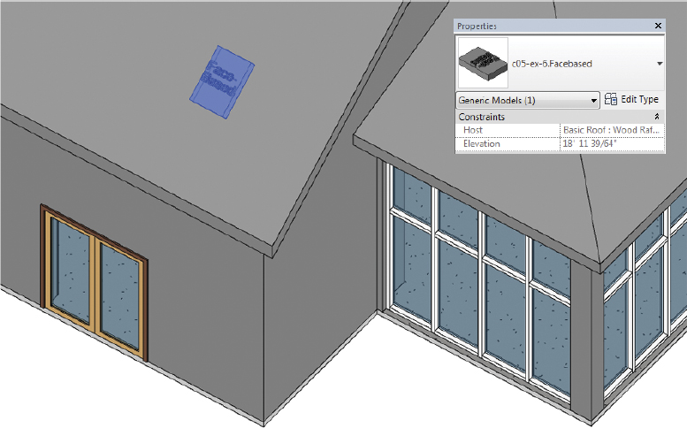
FIGURE 5.12 Face-based family on the roof
- The
- On the Architecture tab in the ribbon, select the Place A Component tool.
- The default family should be
c05-ex-6.Facebased.
- The default family should be
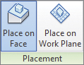
- Before placing a family instance, take note of the ribbon options for Placement.
- Place on Face and Place on Work Plane are available since this is a face-based family (the default should be Place on Face).
- With the placement method set to Place on Work Plane, add several instances of the family to the roof and walls. Notice as you move the cursor over an object that the face will pre-highlight, indicating what the face-based family will be hosted to.
- Now select one of the families you added to a wall.
- In the Properties palette take note of the Host parameter, which is grayed out. This indicates the object the face-based family is attached to. It is an easy reference to know what the family will move with.
- Now delete one of the project walls the
c05-ex-6.Facebasedfamily is hosted to.- Take note of two things. First, the face-based family is not deleted with the host. And second, the Host parameter has updated to <not associated> to indicate the family is no longer associated with a host (Figure 5.13).
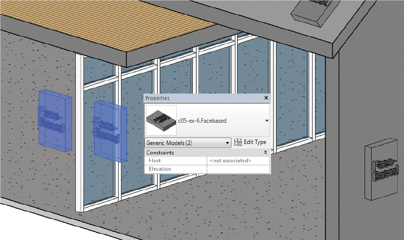
FIGURE 5.13 Face-based family after host deletion
- Take note of two things. First, the face-based family is not deleted with the host. And second, the Host parameter has updated to <not associated> to indicate the family is no longer associated with a host (Figure 5.13).
Working with In-Place Component Families
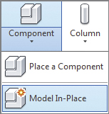
In-Place component families are a special type of component family unique to the current project. They are created in the project environment vs. the Family Editor, so project geometry can be used as a reference. They do not exist outside of the current project. The command is located on the Architecture tab’s Component drop-down; it’s called Model In-Place.
 The major difference between in-place component families and component families is in regard to multiple instances. When component families have multiple instances in the project, updating the family geometry will update all instances. In-Place component families do not support multiple instances of the same family. For this reason, they should be used only for unique geometry since a copy of an in-place component has no relationship to the original (and will not update with changes to the original instance).
In the following exercise you will modify an existing in-place family.
Exercise 5.7: Modify an In-Place Family
To begin, go to the book’s web page at www.sybex.com/go/revit2015essentials, download the files for Chapter 5, and open the file c05-ex-5.7start.rvt.
- Open the project to the default 3D view.
- Select the countertop extrusion, and choose Edit In-Place on the ribbon to edit the Casework family (Figure 5.14).
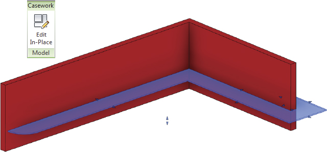
FIGURE 5.14 Edit Casework in-place family
- Unlike the Family Editor environment, take note that you are editing the family in the context of the project. This can be a very useful technique for custom project families where existing conditions or geometry is required to create the family.
- Select the counter extrusion and click Edit Extrusion on the ribbon.
- You want to make a slight change to the shape of the countertop to remove the curved edge.
- Select the curved sketch line and press the Delete key.
- Add a new sketch line creating a 90-degree corner instead, making sure to close the sketch loop.
- When the sketch is complete and closed, click the Finish Edit Mode button.
- Notice that you are still editing the family. This is useful if you needed to create additional extrusions or further modify the family.
- To return to the project and finish editing the in-place family, click Finish Model on the In-Place Editor ribbon panel (Figure 5.15).
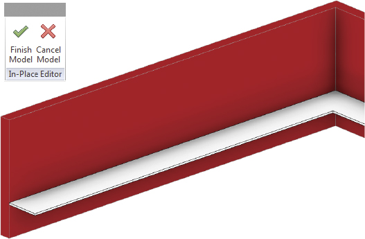
FIGURE 5.15 Complete in-place family
Finding Content
Now that we have reviewed the fundamentals of Revit Architecture families, we’ll discuss one of the most important issues you may face as you start designing: the discovery of suitable content. The best place to begin is with the content installed with Revit Architecture. These default families are created with relatively simple geometry and should be sufficient as a basis for the most common building types. If you installed Revit Architecture with the default settings, you will be able to access the default library whenever you use the Insert tab ![]() Load Family command.
Load Family command.
Autodesk has created an online resource called Autodesk Seek to provide content for its design software (http://seek.autodesk.com). You can search for families on Autodesk Seek directly from Revit Architecture. Let’s explore this option:
- Go to the Insert tab’s Autodesk Seek panel.
- In the search bar, type chairs, and press the Enter key.
- Your default web browser opens to the Autodesk Seek website.
- The results displayed match the search criteria of chairs and are filtered to show only content that offers Revit Architecture families (Figure 5.16).
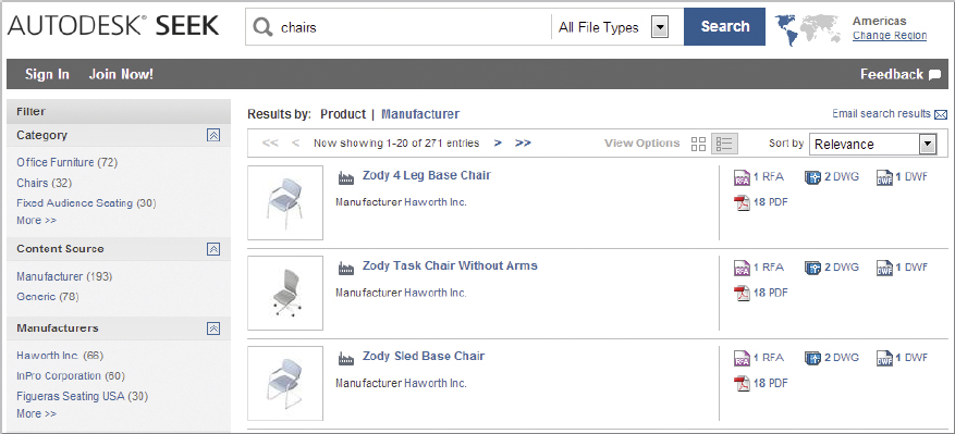
FIGURE 5.16 Content search results in Autodesk Seek
- The results displayed match the search criteria of chairs and are filtered to show only content that offers Revit Architecture families (Figure 5.16).
You will note on Autodesk Seek that you can choose from generic or manufacturers’ content. The generic content is similar to that found in the installed library. Other content should be used with a level of care. Although an exhaustive review of such criteria is outside the scope of this book, here are some aspects you should understand about component families:
Avoid Imported Geometry Component families should not be created by simply opening an RFA file and importing 3D geometry from other modeling software. Content with imported geometry may also adversely affect functions such as rendering. For example, a light-fixture family using an imported CAD model might not have the correct material transparency to allow a light source to render properly.
Watch for Over-Modeling Families should contain only the geometry necessary to document the component. That said, this level of modeling will be slightly different depending on whether you want to create a photorealistic rendering or a construction document. Excessive modeling such as fasteners, switches, knobs, dials, and so on should be avoided.
Use Appropriate Repetition A Revit Architecture family should have a moderate level of repetition built into it. The repetition should not be too complex (all possible variations in one family) or too simple (a separate family for each variation). Reasonable content will offer a family for each set of common geometry (for example, one model line of a light fixture) with types for subtle variations (the various lamping and size options of that light fixture model).