Chapter 7
Schematic Design
Design inspiration comes from any source, at any time. Some designers like to sketch by hand; others use digital tools to create a 3D sketch. When design sketches are digital, the transitions between concept design, schematic design, and design development are simplified.
When you bring a 3D sketch into the Autodesk® Revit® Architecture platform, you start with 3D volumes, primal elements called masses, to make sure your form and square footage are correct before modeling walls and floors. Once you’ve confirmed that your building mass can contain the building program, you will use the mass as an armature on which to place building elements.
In this chapter, you’ll learn to:
- Import a 2D image
- Scale an imported image
- Create a 3D sketch
- Link a 3D sketch
- Add a new level
- Calculate mass floor area
- Reload a linked sketch
- Create floors from a mass
- Create walls from a mass
- Create a curtain system
- Create a roof from a mass
Importing a 2D Image
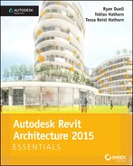
 To create a 2D digital sketch, Autodesk released a tool for Apple’s iPad called SketchBook Pro, which allows you to sketch directly on a tablet using a stylus or your finger like you would use a pen or pencil. The sketch in Figure 7.1 was created on an iPad, but the following steps apply to any scanned image—from either a magazine or trace paper.
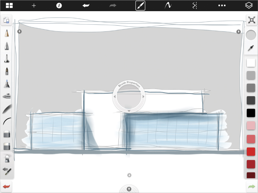
FIGURE 7.1 A 2D sketch from Autodesk SketchBook Pro for iPad
Exercise 7.1: Import and Scale a 2D Image
To begin, go to the book’s web page at www.sybex.com/go/revit2015essentials, and download the files for Chapter 7.
- On the home screen, select Architecture Template to open one of the default Revit Architecture templates. Open the East elevation by double-clicking East in the Project Browser.
 On the Insert tab, find the Import panel, and click the Image button. Select the
 Massing_Sketch.pngfile from theChapter07folder. Click the Open button.- You may need to zoom out to see the preview graphic consisting of blue grips and an X. This preview indicates the size of the image. Click the mouse to place the image. Use the arrow keys to nudge the image so that the ground plane of the building sketch roughly aligns with Level 1, as shown in Figure 7.2.

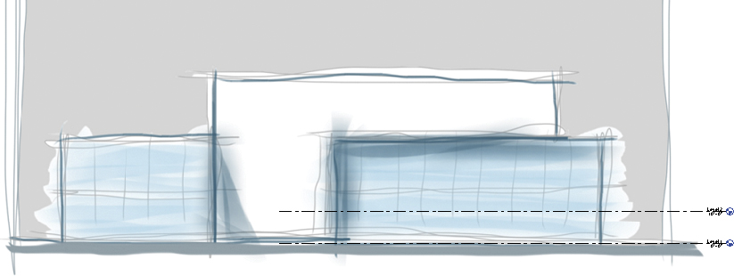
FIGURE 7.2 The imported image. Note the location of the levels relative to the ground plane in the image.
- Zoom into the Level symbols. Select the level line for Level 2. From the Properties palette change the Elevation parameter from 10′-0″ (3.04 m) to 15′-0″ (4.57 m); this height is more consistent with commercial construction.
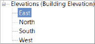
- The image is a bit out of scale for the Revit model. Select the image and choose the Scale tool from the Modify panel. Refer to Figure 7.3 for the eventual goal.
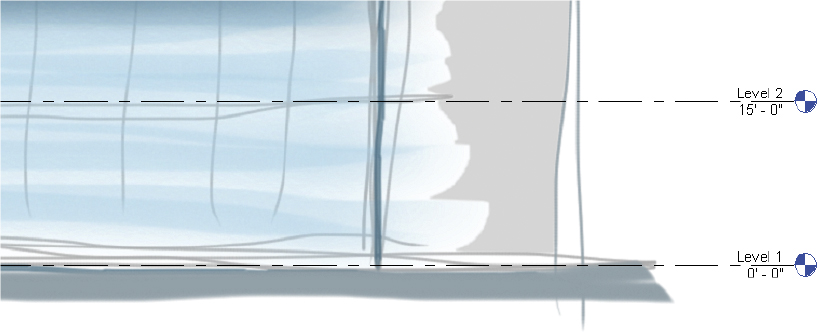
FIGURE 7.3 The scaled image
- Hover the mouse over Level 1 until it highlights blue and then click. This is the shared base point.
- Move your mouse straight up so the cursor roughly aligns with the second floor of the sketch; then click. This is the image reference point.
- Finally, move you mouse straight down so the cursor aligns with Level 2 of the model; then click. This is the model reference point. After this last click, the image scales to look similar to Figure 7.3.
 Once the imported image is scaled and in the right place, it is best to pin the image so it doesn’t accidentally move. Select the image and click the Pin tool from the Modify panel.
This concludes Exercise 7.1. You can compare your results with the sample file c07-ex-07.1end.rvt available in the files you downloaded from the Sybex website.
Designing with a 3D Sketch
 Autodesk has also released a 3D digital sketch tool for iPad and Android devices called FormIt. This is a conceptual design modeling tool that allows you to create building forms and then export the geometry to Revit for further development. The FormIt tablet apps are fun and intuitive, so I recommend you try them out. Figure 7.4 was created on an iPad in roughly 20 minutes. You can upload your 3D sketch to Autodesk 360, automatically convert it to an
 .sat file and a .rvt file, and then download it locally. We’ll go through the steps to link the .sat file into Revit and update the linked file when changes are made.
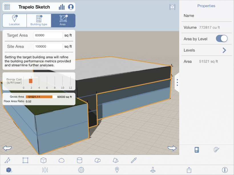
FIGURE 7.4 The FormIt 3D sketch
Exercise 7.2: Link a 3D Sketch
To begin, open the file c07-ex-07.2start.rvt from this chapter’s download.
- To link the 3D sketch you need to insert the FormIt geometry into an In-Place Mass family. On the ribbon, find the Massing & Site tab, then find the Conceptual Mass panel, and click the In-Place Mass icon.

- Revit displays a dialog telling you that it has now enabled Show Mass mode in the current view—but only for this Revit session. Click the Close button. Now Revit allows you to name the Mass; call it Trapelo Sketch and click OK.
- Click the Insert tab of the ribbon and choose Link CAD. A file-navigation dialog appears. This dialog defaults to show
.dwgfiles. Click the Files Of Type drop-down, and choose ACIS SAT files. Select theTrapelo_Sketch.satfile from theChapter07folder. Click Open.
- The geometry should appear successfully on Level 1 of your model. Click the Finish Mass button from the ribbon. Then click the 3D View button on the View tab of the ribbon. Your geometry and view should look like Figure 7.5.
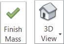
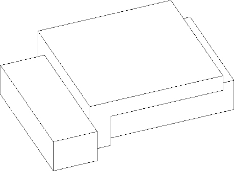
FIGURE 7.5 The linked 3D sketch as an in-place mass
- Click the View tab, and then click the Visibility/Graphics button from the Graphics tab (or type the keyboard shortcut VG). Find the Mass category in the list, and check the box next to it. This way your mass will be visible in this view in the next exercise.
This concludes Exercise 7.2. You can compare your results with the sample file c07-ex-07.2end.rvt available in the download from the Sybex website.
Exercise 7.3: Add a New Level
To begin this exercise, open the file c07-ex-07.3start.rvt.
- Open the North elevation view from the Project Browser. The mass is visible because the category is checked in the Visibility/Graphic Overrides dialog.

- Go to the Architecture tab of the ribbon, find the Datum panel, and click the Level tool.
- In the Draw panel, choose the green Pick Lines tool.
- On the Options Bar, set the offset value to 15′-0″ (4.57 m).
- Hover your mouse over the Level 2 annotation element. Look for a dashed blue line to appear above Level 2. This dashed line indicates where the new level will be placed; see Figure 7.6.
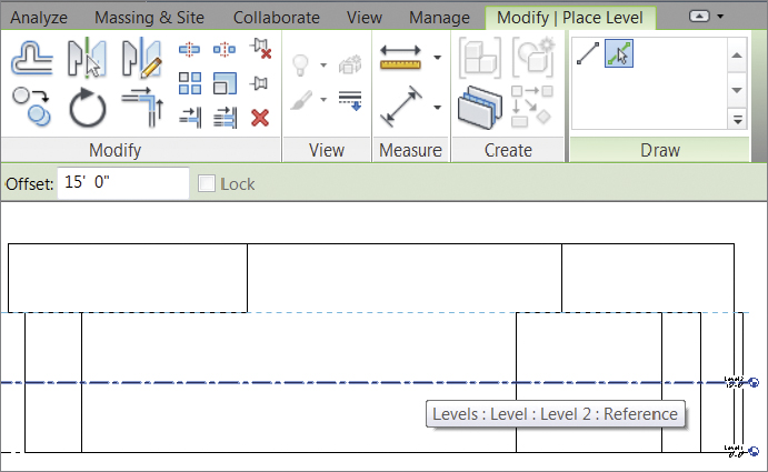
FIGURE 7.6 Use the Pick Lines tool to create a new level.
- Click to place the new level, called Level 3, at 30′-0″.
This concludes Exercise 7.3. You can compare your results with the sample file c07-ex-07.3end.rvt from the download for this chapter.
Exercise 7.4: Calculate Mass Floor Area
 Open the file
 c07-ex-07.4start.rvt from the download to start this exercise.
- The file should open in the 3D view. Select the Mass element, and click the Mass Floors button in the ribbon.
- Check the box next to Levels 1, 2, and 3; then click OK. The Mass element has been divided at the level intersections.
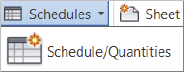
- Click the View tab; then click the Schedules button and choose Schedule/Quantities.
- In the New Schedule dialog, review the list of categories on the left, find Mass, and expand it. Click Mass Floor, and click OK.
- In the Schedule Properties dialog, in the Fields tab, choose the following parameters from the list on the left; then click the Add button. Add them in this order: Mass: Family, Level, Floor Area (see Figure 7.7).
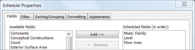
FIGURE 7.7 The list of Mass Floor parameters
- Click the Formatting tab. Choose the Floor Area parameter from the list on the left. Check the Calculate Totals box from the options to the right.
- Now click the Sorting/Grouping tab. Check the box for Grand Totals; then choose Totals Only from the drop-down list. Click OK.
- You can see that the Floor Area total is roughly 51,500 SF (15,697.2 m), as shown in Figure 7.8. This is valuable information to have early on in schematic design.
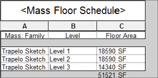
FIGURE 7.8 The Floor Area schedule
This concludes Exercise 7.4. You can compare your results with the sample file c07-ex-07.4end.rvt that you downloaded earlier.
Exercise 7.5: Reload a Linked Sketch
To begin, open the file c07-ex-07.5start.rvt.
- If the design changes, the 3D sketch changes, and you’ll need to update the linked building mass by reloading the
.satfile. Open the 3D view. - Go to the Insert tab of the ribbon, and click the Manage Links button on the Links panel. Click the CAD Formats tab of the dialog.

- Click the cell named
Trapelo_Sketch.sat. Then click the Reload From button from the options below it. - The Find Link dialog appears. From the
Chapter 7folder, choose the file namedTrapelo_Sketch_Update.satand click Open. - Click OK to confirm the changes in the Manage Links dialog.
- The building mass has updated slightly. Revit automatically recalculates the mass floors as well. Go to the Schedules/Quantities node of the Project Browser and open the Mass Floor Schedule. The Floor Area total is now 55,201 SF (16,825 m).
This concludes Exercise 7.5. You can compare your results with the sample file c07-ex-07.5end.rvt available in the download.
Creating Revit Elements from a Mass
Once your mass is approximately the right size and shape, you can start to advance from the conceptual design phase to early design development. The mass itself has few properties aside from area and volume. You need to add building elements like floors, walls, and curtain systems to enclose and define your building. Revit uses the mass as an armature to place these real model elements upon.
Exercise 7.6: Create Floors from a Mass
 To start this exercise, open the file
 c07-ex-07.6start.rvt.
- The file should open in the 3D view. Go to the Massing & Site tab, find the Model By Face panel, and then click the Floor tool.
- Select the three mass floors; this is easy to do because you are allowed to select only mass floors in this tool.
- After choosing all three mass floors, click the Create Floor button in the ribbon. Now you have real Revit floors that will be displayed in all views. The benefit of creating floors by face is that you don’t need to sketch a custom shape for any of your floors—Revit uses your mass floor to automatically generate the floor outline.
This concludes Exercise 7.6. You can compare your results with the sample file c07-ex-07.6end.rvt.
Exercise 7.7: Create Walls from a Mass
 Open the file
 c07-ex-07.7start.rvt to begin this exercise.
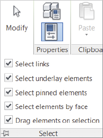
- In order to make the next steps easier, turn on Face Selection. Find the Modify button on the far-left side of the ribbon, and click the Select button underneath it. Now check the box next to Select Elements By Face.
- Go to the Massing & Site tab, find the Model By Face panel, and then click the Wall tool. You will place solid walls now and place glass walls in the next exercise. Hover your mouse over one of the third-floor walls, as in Figure 7.9. Click to place a new wall.

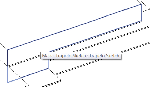
FIGURE 7.9 Place a solid wall by face.
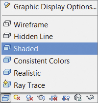 It is difficult to differentiate the mass from the Revit wall. To show which walls have been created and which still need to be placed, adjust the graphics by changing the visual style from Hidden Line to Shaded.
- Open the Visibility/Graphic Overrides dialog by typing the shortcut VG. Find the Floors category, and uncheck the box next to it.
- Also in the Visibility/Graphic Overrides dialog, find the Mass category and click into the cell in the third column titled Transparency; then click again to make the Surfaces dialog appear. Set the Transparency value to 50. Click OK.
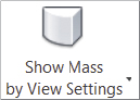
- Also in the Visibility/Graphic Overrides dialog, expand the Mass node. Uncheck the box next to the Mass Floor subcategory. Click OK to confirm all of these changes to the Visibility/Graphic Overrides dialog. Make sure that the Massing & Site tab has the Show Mass By View Settings button enabled.
- Now the mass and walls are distinguishable. Click the Massing & Site tab, choose the Wall By Face tool, and click to place walls until the volume in the middle of the mass looks like Figure 7.10.
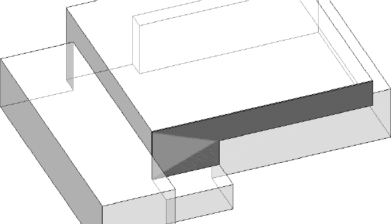
FIGURE 7.10 Place the solid walls by face.
This concludes Exercise 7.7. You can compare your results with the sample file c07-ex-07.7end.rvt.
Exercise 7.8: Create a Curtain System
 To begin this exercise, open the file
 c07-ex-07.8start.rvt.
- To place the glass walls on the mass you’ll use a different tool called the Curtain System. Go to the Massing & Site tab and click the Curtain System button.
- You can change the spacing of the grids from the defaults. Click the Edit Type button in the Properties palette. Click the Duplicate button, and rename the type to 10′ (3.04 m) × 5′ (1.524 m) -Trapelo. Click OK to confirm the new name.
- Change the Grid 1 Spacing parameter from 10′-0″ (3.04 m) to 5′-0″ (1.524 m). Change the Grid 2 Spacing parameter from 5′-0″ (1.524 m) to 10′-0″ (3.04 m). Click OK to confirm these changes to the Curtain System type.

- Click all of the vertical faces that will become glass walls. You will have to use the ViewCube to rotate the view in order to see the vertical faces on the other side of the building. One word of caution—you are allowed to click horizontal faces of the mass (like roofs), so be careful clicking!
- Click the Create System button from the ribbon. Click Esc to close the tool. Your model should look like Figure 7.11.
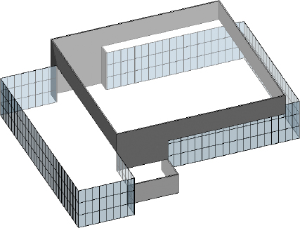
FIGURE 7.11 Curtain systems added to the mass
 This concludes Exercise 7.8. You can compare your results with the sample file
 c07-ex-07.8end.rvt.
Exercise 7.9: Create a Roof from a Mass
Open the file c07-ex-07.9start.rvt to begin this exercise.
- The last building element needed to enclose the design is the roof. Click the Massing & Site tab, and choose the Roof By Face tool.

- Click the four horizontal surfaces that need a roof element. Then click the Create Roof button from the ribbon.

- Type the keyboard shortcut VG to access the Visibility/Graphic Overrides dialog box. Turn the Floors category back on.
- Uncheck the Mass category in the same dialog.
- Click OK. Your finished schematic design should resemble Figure 7.12.
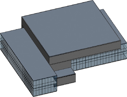
FIGURE 7.12 Finished schematic design
This concludes Exercise 7.9. You can compare your results with the sample file c07-ex-07.9end.rvt.