Chapter 9
Materials, Visualization, Rendering
Being able to visualize an architectural building before completion is one of the many advantages of building a 3D model. The Autodesk® Revit® Architecture platform offers various opportunities for you to visualize your design in exciting ways. We’ll discuss how to set the material properties for your building information model, create compelling presentation graphics, and then produce beautiful renderings. As you become a skilled Revit user, you will also become a visualization expert.
In this chapter, you’ll learn to:
- Define a material
- Assign a material to walls
- Apply presentation graphics to an elevation view
- Apply presentation graphics to a 3D axon view
- Make an exploded axon
- Render a model
- Create an interactive rendering
- Render a model using the cloud
Materials
Materials have many applications within Revit Architecture. In this chapter, we’ll talk about the Graphic and Appearance tabs of the Material Editor to help you create and control the visualizations of your design. First we’ll discuss how to create materials in your model. Then we’ll apply a material to a brick wall.
Exercise 9.1: Define a Material
To begin, go to the book’s web page at www.sybex.com/go/revit2015essentials, download the files for Chapter 9, and open the file c09-ex-09.1start.rvt.
- Go to the Manage tab of the ribbon and click the Materials button on the far left. This will open the Material Browser, where you define your materials.

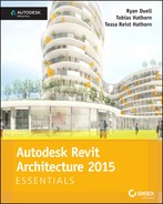
- The Material Browser dialog has a list of material names to the left with a very helpful search box at the top of the list. Type the word Brick into the search field, and the list will filter to only one material named Masonry - Brick.
- Click the Masonry - Brick material and notice that the properties on the right update, as in Figure 9.1. You’re looking at the Graphics tab of the material’s properties. You can choose a unique color for the brick by clicking the Color button under the Shading header. You can also redefine the surface pattern. The brick pattern looks good, so leave it as is.
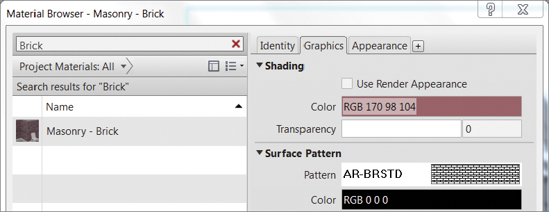
FIGURE 9.1 Search results for Brick and the Graphics tab
- Now click the Appearance tab and you’ll see a small rendered preview of the brick material (Figure 9.2). Below this preview are properties that affect the way this material looks in renderings. Above the preview image are buttons related to the material asset. Click the icon with arrows that allows you to replace the asset with a different material map.
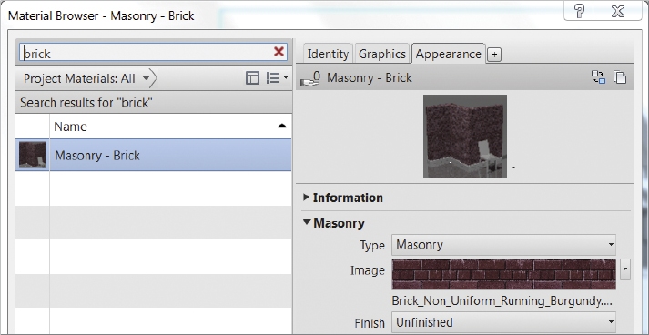
FIGURE 9.2 The Appearance tab and the swap icon
- The Asset Browser dialog appears (Figure 9.3), and it also has a search field at the top. Type in Brick; then click the Masonry option under the
Autodesk Physical Assetsfolder and you’ll see a variety of options. You should drag the column widths so you can see the material asset names. Double-click the Non-Uniform Running - Red brick material.
FIGURE 9.3 The Asset Browser
- The preview in the Appearance tab updates. Click the Graphics tab again, and check the Use Render Appearance box; see Figure 9.4. The shaded color updates to reflect an average color sample from the material render appearance! This is very helpful for consistency between different visual styles. Click OK to exit.
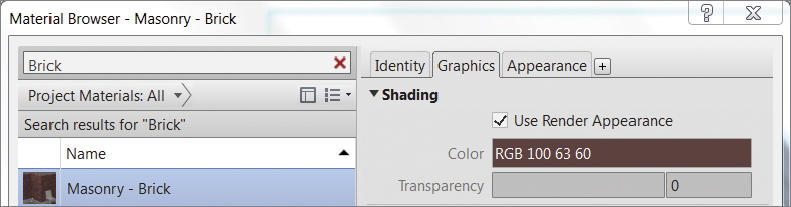
FIGURE 9.4 The finished Graphics tab
This concludes Exercise 9.1. You can compare your results with the sample file c09-ex-09.1end.rvt included in the chapter’s download.
Exercise 9.2: Assign a Material
To begin, open the file c09-ex-09.2start.rvt from the chapter’s download.
- Make sure you’re in the 3d Cover Shot view, and change your visual style to Shaded by using the icon on the View Control Bar.
- Select one of the gray walls (Figure 9.5). Then, in the Properties palette, click the Edit Type button to open the Type Properties dialog box for the wall you have selected, Basic Wall 8 1/2″ (21 cm) Masonry.
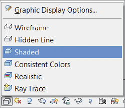
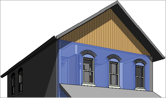
FIGURE 9.5 Select the gray wall.
- Find the Construction header to the right of the Structure label, click the Edit button, and the Edit Assembly dialog box will appear. Find the Material column, and click into the first cell; it currently says Default Wall. Notice that a small button appears in the cell. Click the button.
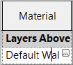
- The Material Browser dialog appears. Type Brick into the search field at the top of the list. Double-click the Masonry - Brick material that appears in the list on the left. This is the material you edited in the previous exercise. Click OK to close the Edit Assembly dialog, and click OK again to close the Type Properties dialog. The drawing updates dramatically by replacing the gray material with a nice red brick shading!
- You’ve now applied your new material called Brick to all the walls of the type Basic Wall 8 1/2″ (21 cm) Masonry throughout your model. You can follow the same steps to apply materials to floors, roofs, and other walls in your projects.
This concludes Exercise 9.2. You can compare your results with the sample file c09-ex-09.2end.rvt included in the chapter’s download.
Graphic Display Options
Now that you understand the basics of assigning building materials to your model elements, you will open an example file that has many materials and views already set up. You’ll use this model to create a presentation drawing of an elevation and a 3D isometric drawing. You won’t use rendering, just the techniques available in the Graphic Display Options.
Exercise 9.3: Presentation Elevation View
To begin, open the file c09-ex-09.3start.rvt.
- Find the East elevation in the Project Browser. Right-click the name East and choose Duplicate View, and then in the flyout menu choose Duplicate (Figure 9.6). This will make a copy of the view but without copying detail annotation elements.

FIGURE 9.6 Duplicate a view from the Project Browser.
- Right-click the newly created view in the Project Browser, named East Copy 1, and click Rename. Type in a new name, East — Presentation. Next you’ll turn off the level markers and the reference planes in the view.
- Select one of the green dashed reference planes, right-click, and choose Hide In View
 Category (Figure 9.7). All of the reference planes are now hidden. Select one of the level datum graphics, right-click, and choose Hide In View Category. Notice that all of the level markers are now hidden.

FIGURE 9.7 Hide the category in the view.
- Now you are ready to embellish the presentation drawing with effects found in the Graphic Display Options (GDO) dialog box. Open the GDO from the Properties palette by clicking the Edit button next to the Graphic Display Options view parameter.
- Click the Smooth lines with anti-aliasing check box. This effect improves the line quality in the view dramatically. It has a negative performance impact, so use it in presentation views only.
- Expand the Shadows section. Click the Cast Shadows and Show Ambient Shadows check boxes. Click the Apply button at the bottom of the dialog to see the effect these have on the model.
- Expand the Sketchy Lines section, and click the Enable Sketchy Lines check box. Slide the Extensions control to 7, and click Apply.
- Expand the Lighting option, and find the Shadow slider. Slide this to the left to make your shadows lighter. Click Apply and adjust until you’re satisfied with the darkness of the shadows.
- Expand the Background section, and choose Gradient from the options. Click Apply. You should see something similar to Figure 9.8. Click OK to close the GDO dialog.
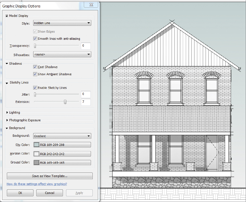
FIGURE 9.8 Elevation presentation view and GDO settings
- The visual effects are all set, but the crop region needs to be adjusted. Select the crop region. Note the blue grips that appear in the middle of the edges. These can be dragged so that the elevation is framed as you desire.
 Once you have the elevation centered in the crop region, you can turn off the crop region. The control for the crop region visibility is on the View Control Bar at the bottom of the screen. Click the Hide Crop Region button. Now you have an elevation view ready to be placed on a sheet.
This concludes Exercise 9.3. You can compare your results with the sample file c09-ex-09.3end.rvt available in the download for the chapter.
Exercise 9.4: Presentation 3D View
To begin, open the file c09-ex-09.4start.rvt from the files you downloaded earlier.
- Open the 3D view titled 3D Isometric in the Project Browser. The view is locked so that you cannot accidentally change the angle of the view. You can unlock the view by clicking the Unlock 3D View button on the View Control Bar, next to the Hide Crop Region button.

- Click the Visual Style button on the View Control Bar, and choose the Shaded option. Then click the Visual Style button again, but this time click the Graphic Display Options text at the top of the list. This is a handy shortcut to the GDO dialog.
- Check the Smooth lines with anti-aliasing, Cast Shadows, and Show Ambient Shadows check boxes. Turn on Enable Sketchy Lines and set the Extension slider to 7. Set the Background option to Gradient. Click Apply to see these effects.
- Expand the Lighting option, and adjust the Shadows, Sun, and Ambient Light slider controls. The Sun and Ambient Light sliders make an impact when your visual style is set to Shaded or Realistic. Set each of these values to 40, and click OK. You may need to zoom in a bit to see the surface patterns; then your view should look like Figure 9.9.
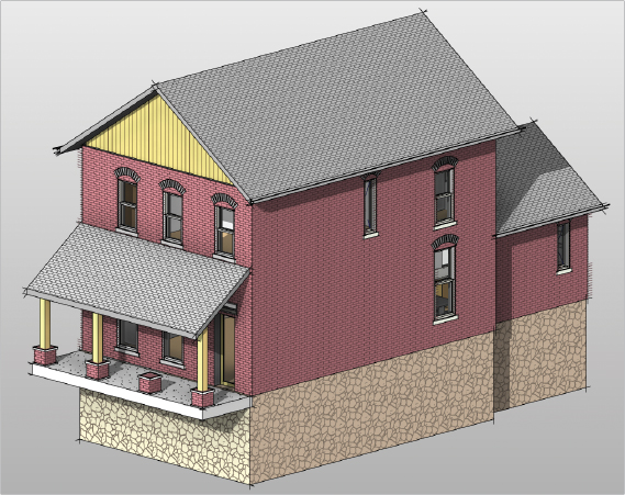
FIGURE 9.9 3D Isometric with GDO effects
- Select the large brick wall that is blocking your view into the house. Right-click and choose Override Graphics In View By Element. Click the arrow next to Surface Transparency, and use the slider to set the value to 40. Click OK, and deselect the wall by hitting the Esc key twice.
- You can see into the house, but the brick surface pattern is still obscuring the view. Select the wall again, right-click, and choose Override Graphics In View By Element. Expand the Surface Patterns control, and uncheck the Visible parameter as in Figure 9.10 Click OK, and then press Esc to deselect the wall.
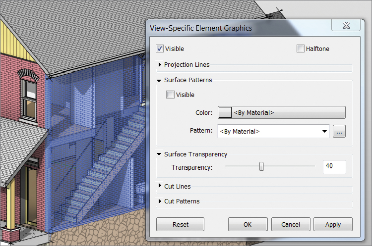
FIGURE 9.10 Selected wall and element overrides
This concludes Exercise 9.4. You can compare your results with the sample file c09-ex-09.4end.rvt available in the chapter’s download.
Exercise 9.5: 3D Exploded View
To begin, open the file c09-ex-09.5start.rvt from the files you downloaded for this chapter.
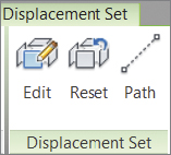
- Open the view 3D Exploded View. Select the large brick wall, and click the Displace Elements button on the View panel of the Modify tab.
- A widget appears with green, red, and blue arrows. This widget allows you to move the displaced set of elements. Click and drag the red arrow away from the house. Release the mouse button to place the wall. With the wall still selected, look in the Properties palette for the X Displacement value. Set this value to 25′-0″ (7.6 m).
- Since the windows are hosted in the wall, they move with it. You can displace these elements farther from the wall. Hover your mouse over a window, and click the Tab key until the window highlights. Select the window; then hold down Ctrl and click the other two windows so you have all three selected. Click the Displace Elements button. In the Properties palette, set the X Displacement value for the window to 20′-0″ (6 m).
- Click any of the displaced windows to select the displacement set, and from the ribbon choose the Path tool. Hover your mouse over one of the corners of your displaced windows. Click to add a dashed line back to where the element originated; repeat for the other corners. If you accidentally add a path line you don’t want, you can select it and click Delete on the keyboard.
- Now you can add graphic effects using the GDO to make a beautiful and informative presentation drawing using steps from the previous exercises. Your results may look like Figure 9.11.
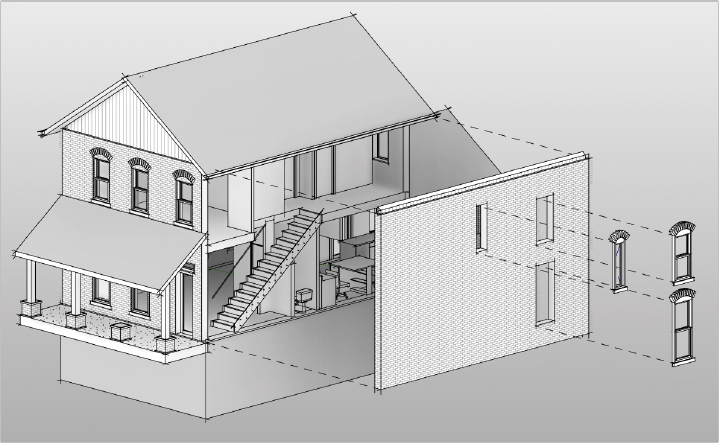
FIGURE 9.11 Finished exploded vie
This concludes Exercise 9.5. You can compare your results with the sample file c09-ex-09.5end.rvt from the files you downloaded.
Rendering
The technique of computer rendering is a complex science that has been simplified and tailored for architects in Revit Architecture. There are many expert computer renderers in the architecture field, and we recommend this tutorial as an initiation to the activity of rendering.
Exercise 9.6: Render a View
To begin, open the file c09-ex-09.6start.rvt from the chapter’s download.
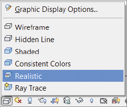
- Open the view 3D Cover Shot. Get a quick preview of the render appearance of the materials used in the scene by switching to the Realistic visual style using the View Control Bar.
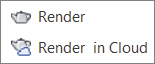 Open the Rendering dialog by clicking the teapot icon in the View Control Bar or by clicking the Render button on the View tab. This dialog does not have an OK or Cancel button. It has a big Render button at the top. Click Render now.
- Congratulations, you’ve just made a Revit rendering! Now let’s refine the quality of this image. First, change the Quality setting to Medium, and click Render again. Then, change the Quality setting to High, and click Render again. Note that changing the Quality setting improves the rendering but lengthens the time it takes to finish the rendering. Change the Quality setting back to Medium for the rest of this exercise.
- Click the Sun Settings button in the Lighting group. The dialog that opens allows you to specify the location of the sun during your rendering. Change the time from 10:15 a.m. to 1:15 p.m. (Figure 9.12), and click OK. Click Render again to see how this iteration changes the rendering.
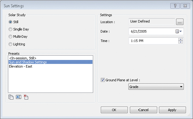
FIGURE 9.12 Sun Settings dialog box
- Click the Adjust Exposure button. The very first slider control in this list allows you to lighten or darken the image. Adjust the Exposure Value parameter to 13. The other sliders are useful if you want to adjust the colors of your image without using photo-editing software. Click OK, and notice the changes made — without having to re-render!
- Find the Output Settings group. So far in this tutorial you’ve been rendering at screen resolution, so the rendering will finish faster. Click the Print radio button. When switching to print output, you can specify the DPI. The higher the DPI, the longer the rendering takes. To have crisp edges in your finished rendering, set DPI to 150.
- Once this rendering finishes (Figure 9.13), click the Save To Project button. This will prompt you to name the image. The image will be saved in your Project Browser under the Renderings branch. You can also click the Export button, which will save your rendering to your computer’s hard drive as a
.bmp, .jpg, .png, or.tiffile.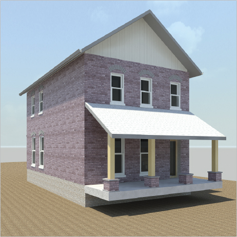
FIGURE 9.13 The finished rendering
- You can continue to test different rendering quality settings and background options. Rendering is an iterative process; working from low quality toward high DPI is a fast way to reach a finished image. If you want to select a wall or change a material, you can click the Show The Model button at the bottom of the dialog to switch from a static rendered image back to the model.
This concludes Exercise 9.6. You can compare your results with the sample file c09-ex-09.6end.rvt in the downloaded files for this chapter.
Exercise 9.7: Interactive Rendering
To begin, open the file c09-ex-09.7start.rvt from this chapter’s download.
- In the Project Browser, find the 3D Views node, right-click the 3D Cover Shot view, and choose Duplicate View Duplicate. Rename the new view Interactive Rendering.
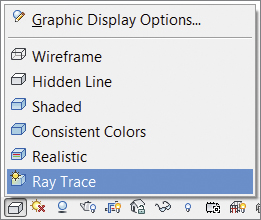
- Change the visual style of the new view to Ray Trace using the View Control Bar. Ray Trace is a temporary, interactive rendering mode, where you can use the navigation wheel to pan, zoom, and orbit your model.
- The rendering in Ray Trace mode will automatically start. At first, the image will be low quality and low resolution, but it will improve quickly the longer you let the view idle. When you begin navigating your model, the rendering will restart as soon as you stop navigating and let the view idle.
- To change the rendering settings for Ray Trace mode you need to access the GDO. You can type the keyboard shortcut GD or click the Visual Style menu on the View Control Bar. Make sure to change the Background setting to Sky. You can also brighten the scene using the Manual option of Photographic Exposure. Finally, you can change the Sun location in Sun Settings; click OK. In the GDO dialog click Apply to preview the changes, and then click OK when you’re ready.
- Click the navigation wheel icon, and use the Orbit command, the Walk command, as well as the Pan command to move the camera to various vantage points. The Look command is especially useful on interior scenes. When you find an interesting camera angle, you can stop there and let the Ray Trace rendering improve for a few seconds (Figure 9.14).
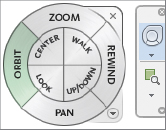
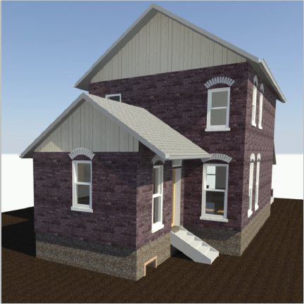
FIGURE 9.14 A Ray Trace rendering after 15 seconds
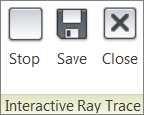
- You can save the image to the Renderings node of your Project Browser. Just click the Save button from the ribbon. Name the rendering Back of House. Finally, click the Close button on the ribbon to exit Ray Trace mode.
This concludes Exercise 9.7. You can compare your results with the sample file c09-ex-09.7end.rvt from the files you downloaded for this chapter.
Exercise 9.8: Cloud Rendering
Autodesk offers a very reliable and fast service that will render your Revit views in the cloud, thus allowing you to continue working while your renderings process somewhere else.
To begin, open the file c09-ex-09.8start.rvt in this chapter’s download.
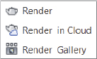
- To use the cloud service, click the Render in Cloud button on the View Tab. You will be asked to sign in using your Autodesk 360 account. Create an account if you don’t have one. After logging in, you should see a Render in Cloud dialog box with a few informational steps for cloud rendering; click Continue.
- The Cloud Rendering Service provides an interface for you to select which views you’d like to have rendered. First, expand the 3D View drop-down; then check the boxes for Interactive Rendering and 3D Cover Shot — or choose to render all five of the 3D views.
- There are other options below, but as long as you set Render Quality to Standard and Image Size to Medium (1 Mega Pixel), then the renderings do not cost any cloud credits; they are free! See Figure 9.15.
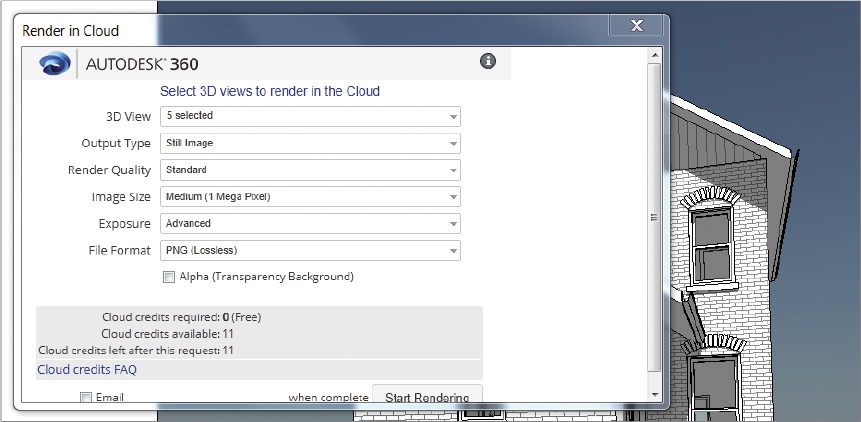
FIGURE 9.15 Render In Cloud options
- Click the Start Rendering button at the bottom of the dialog. Revit will process for a few moments as your model is uploaded to the cloud service. Then you’ll be able to work on modeling while the renderings are finished on another machine.
- In a few minutes, you will get an e-mail, or your communication center will notify you that your renderings are ready. Click the Render Gallery button on the ribbon and review your new rendered images.
- You can get these renderings back into your Revit project by saving them from the cloud onto your desktop. Then duplicate the Back of House view from the Renderings node of the Project Browser. Rename the copied view Cloud Cover Shot. Delete the old rendering, and import one of the new renderings as an image file to the blank drafting view.
This concludes Exercise 9.8. You can compare your results with the sample file c09-ex-09.8end.rvt in the files you downloaded earlier.