Chapter 13
Workflow and Site Modeling
Understanding the Autodesk® Revit® Architecture software and how to use it is not a difficult challenge. The real challenge is determining how using Revit Architecture and building information modeling (BIM) will change your organization’s culture and your project’s workflow, especially if you’re coming from a CAD-based environment. Revit Architecture can be more than just a different way to draw a line. In this chapter, we’ll focus on what those changes are and provide some tools to help you manage the transition.
In this chapter, you’ll learn to:
- Staff a BIM project
- Model a site
- Create a building pad
- Purge unused families and groups
- Manage links and images
- Reduce number of views
- Maintain project warnings
Understanding a BIM Workflow
Regardless of the workflow you have established, moving to Revit Architecture is going to be a change. You’ll need tools to help transition from your current workflow to one using Revit Architecture. To begin, we’ll cover some of the core differences between a CAD-based system and a BIM-based one.
Moving to BIM is a shift in how designers and contractors look at the design and documentation process throughout the entire life cycle of the project, from concept to occupancy. In a traditional CAD-based workflow, represented in Figure 13.1, each view is drawn separately with no inherent relationship between drawings. In this type of production environment, the team creates plans, sections, elevations, schedules, and perspectives and must coordinate any changes between files manually.

FIGURE 13.1 A CAD-based workflow
In a BIM-based workflow, the team creates a 3D, parametric model and uses this model to automatically generate the drawings necessary for documentation. Plans, sections, elevations, schedules, and perspectives are all by-products of creating an embellished BIM model, as shown in Figure 13.2. This enhanced documentation methodology not only allows for a highly coordinated drawing set but also provides the basic model geometry necessary for analysis, such as daylighting studies, energy, material takeoffs, and so on.

FIGURE 13.2 A BIM workflow
Using Revit Architecture becomes more than a change in software; it becomes a change in workflow and methodology. As various design specializations interact and create the building model (Figure 13.3), you can see how structure, mechanical, energy, daylight, and other factors inform design direction. You can also draw relationships between some of these elements that might not have been as obvious in a more traditional approach. Although some of these specialties (such as structure and mechanical) are historically separate systems, by integrating them into a single design model, you can see how they interact in relation to other systems within a building.
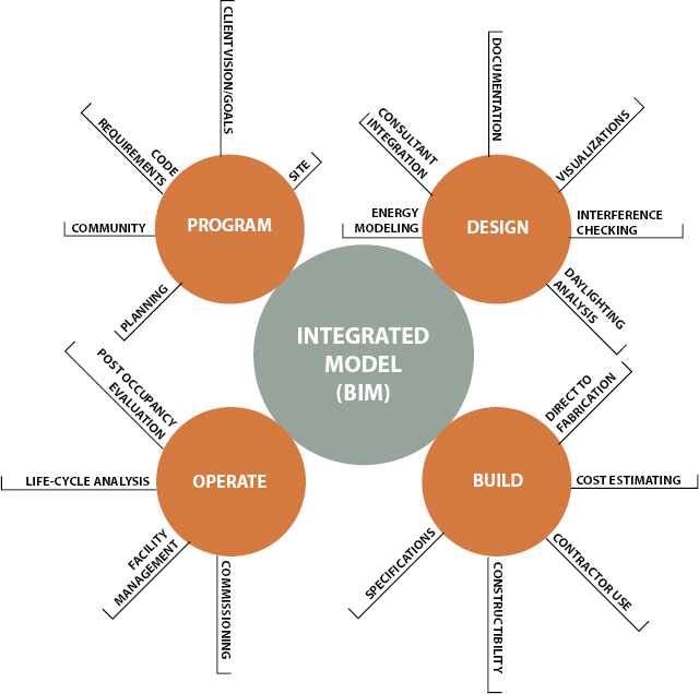
FIGURE 13.3 The integrated design model
Analysis such as daylighting can inform your building orientation and structure. Depending on your glazing, it can also affect your mechanical requirements (as solar gain). You can see some of these effects through a computational fluid dynamics (CFD) model (used to calculate airflow). Geographic information system (GIS) data will give you your relative location globally and allow you to see how much sunlight you will be receiving or what the local temperature swings will be during the course of a day. As you can see, all of these variables can easily affect building design.
Staffing a BIM Project
As you rethink the process of design and documentation, one of the semantic changes you will need to address is staffing. When the workflow changes from CAD to BIM, staffing allocations, time to complete tasks, and percentage of work by phase are all affected as a by-product of the change of method.
In a CAD-based project, the level of effort during each of the phases is fairly well known. The industry has been using some metrics over the past several years that should be fairly familiar. There is modest effort and staffing in the conceptual design and schematic design phases, and this effort builds until it crescendos during construction documentation. At this phase, a CAD project can greatly increase the number of staff in an effort to expedite the completion of the drawing set. This staff increase can be effective because the CAD drawings are typically separate files, and moving lines in one drawing won’t dynamically change another.
In a BIM-based framework, there is still a gradual increase of staffing and effort through conceptual design and into the schematic phase, but the effort during schematic design is greater using BIM than in CAD. During schematic design and design development, the project team is still performing all the same tasks that occur in any design process: testing design concepts, visualizations, or design iteration. The increase in effort during the early design phases lets the team use the parametric nature of the model to significantly reduce the effort later during construction documents, allowing for a decrease in the overall effort over the project cycle.
Project Roles Using Revit Architecture
With such a significant change in the effort behind a BIM-based project flow, it’s also important to understand how this can change the various roles and responsibilities for the project team. The changes in traditional roles can become a barrier to many projects successfully adopting BIM. Project managers need to be able to predict staffing and time to complete tasks throughout the project phases and have relied on the past precedent of staff and project types to do this. Because a BIM-based project can significantly alter the project workflow, many of the historic timetables for task completion are no longer valid. However, a BIM-based project can be broken down into a few primary roles that will allow you some level of predictability through the various project phases. Although the specific effort and staffing will vary between offices (and even projects), some general roles will need to be accounted for on every project.
There are three primary roles on every BIM project.
Architect Deals with design issues, code compliances, clear widths, wall types, and so on
Modeler Creates content in 2D or in 3D
Drafter Deals with annotations, sheet layout, view creation, and detail creation
These roles represent efforts and general tasks that you need to take into account on any Revit Architecture project. We’ll now cover each of these in a bit more detail and discuss how these roles interact with the project cycle.
Architect
The role of the architect is to deal with the architectural issues revolving around the project. As the model is being created, you will naturally have to solve issues such as constructability and wall types, set corridor widths, deal with department areas, and deal with other issues involving either codes or the overall architectural design. This role will be the one applying standards to the project (as in wall types, keynotes, and so on) and organizing the document set. This role will need to be present on the project from the beginning to ensure consistency of the virtual building creation and isn’t necessarily limited to only one person.
This role also might or might not be a “designer.” Although it is possible to do early design in Revit Architecture, many project teams prefer to utilize other tools such as Trimble SketchUp or even pencil and trace paper. The job of the architect is steering the creation of the building in Revit Architecture. Tasks for this role include the following:
- Leading the creation of massing (if used) and major architectural elements and then building from within the model
- Designing around code requirements and other building logistics
- Ensuring constructability and detailing aspects of the design
Modeler
The role of the modeler is to create all the 2D and especially the 3D content needed in the project. This content includes all the parametric families for elements such as windows, doors, casework, wall types, stairs, railings, and furnishings. Typically, this role is the responsibility of less experienced staff who might not be able to fulfill the role of architect. These less experienced positions tend to have longer periods of undisturbed time, making them better suited to deal with some of the longer, more involved tasks in modeling content. Finally, they also tend to have some 3D experience coming out of school. They might not have worked with Revit Architecture directly but possibly with Autodesk® 3ds Max® or Trimble SketchUp and are thereby familiar with working in a 3D environment. Tasks for this role include the following:
- Exchanging any generic elements used during early design stages for more specific building elements
- Creating and adding new family components and modifying existing components in the project
- Regularly reviewing and eliminating project warnings
Drafter
The role of the drafter is to create sheets and views and embellish those views with annotations or other 2D content. This role will be doing the bulk of the work needed to document the project. In earlier stages of the project, this role is typically assumed by either the architect or the modeler, but as documentation gets moving into high gear, it can quickly become the role of multiple people on a larger project. Tasks for this role include the following:
- Keynoting
- Dimensioning
- Setting up sheets and views
- Creating schedules
For a staffing-planning purpose, we are discussing the ideal times to bring in some of these various roles into the project. At the inception of a project design, a modeling role will be of the best use. This person can help create the building form, add conceptual content, and get the massing for the building established. If you’re using the conceptual modeling tools, the modeler can even do some early sustainable design calculations.
Once the design begins to settle down, you’ll need an architect role to step into the project. Since the design is more resolved, it’s a good time to begin applying specific materials and wall types and validating spatial requirements and the owner’s program. The process of moving from the general “what” something is and “where” it is to the more specific “how” something is going to be assembled isn’t new. It’s the same process that was used to create both traditional and modern buildings (Figure 13.4).
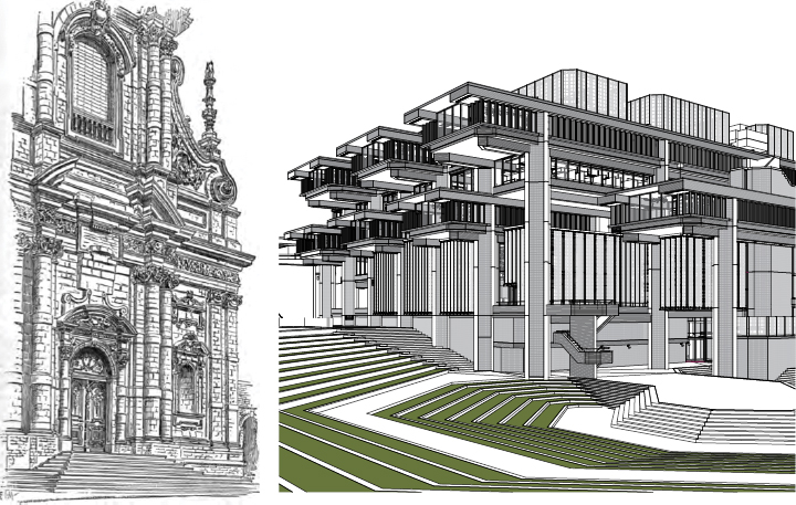
FIGURE 13.4 Traditional and modern designs
During schematic design, you’ll need to include the role of the drafter to begin laying out sheets and creating views. These sheets and views don’t have to be for a construction document set yet, but you’ll have to establish views for any schematic design submittals. If these views are set up properly, they can be reused later for design development and construction-document submittals as the model continues to gain a greater level of detail.
Adding Team Members to Fight Fires
In many projects, there comes a time when the schedule gets tight and project management wants to add more staff to a project to meet a specific deadline. In a 2D CAD environment, new team members would be added to help meet a deadline and would have the burden of trying to learn the architecture of the building, the thoughts behind its design, and how its various systems interact. In a Revit Architecture project, they have that same obligation, but they have the additional task of learning how the model goes together. The model will have constraints set against various elements (such as locking a corridor width) as well as various digital construction issues (such as how floors and walls might be tied together, what the various family names are, or workset organization). This ramping-up period consumes additional time.
Regardless of planning, deadlines escape the best of architects and project managers. It’s a good idea to know when and how you can staff to make sure you meet deadlines. Keep in mind that any team members new to the project have to learn about both the design and the model they have been thrown into; follow these suggestions so new staff can help production and don’t accidentally break anything along the way:
Create content, content, content. You will find that you are making model families or detail components until the end of the project. This process will help get the newbie engaged in a specific part of the project and also isolate them until they learn more about how the model has gone together.
Put them into a drafting role. Even if this isn’t their ultimate role on the project, having staff new to the design help create views and lay out sheets will get them familiar with the architecture while still allowing the team to progress on the document set.
Start them to work on detailing. Every project can always use someone who knows how to put a building together. If you have someone new to the project and possibly even new to Revit Architecture, let them embellish some of the views already created and laid out on sheets. These views can be layered with 2D components, linework, and annotations.
Modeling a Site
In the previous sections of this chapter, you learned about the fundamental roles and workflow for your project team. Now let’s talk about some other less frequently used tools. Another set of tools you should become familiar with are the site tools. They allow you to create a context in which your building models can be situated. For example, a toposurface will create a hatched area when you view your building in a section, and it will function as a hosting surface for site components such as trees, shrubs, parking spaces, accessories, and vehicles (Figure 13.5).
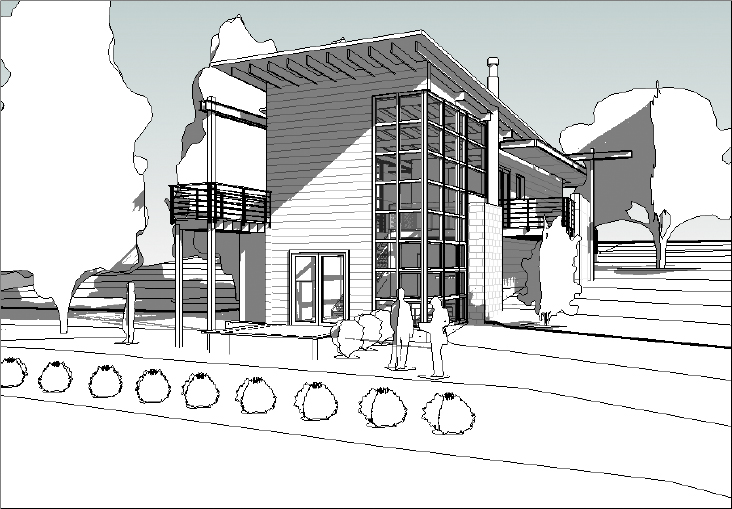
FIGURE 13.5 A toposurface can host components such as trees, entourage, and vehicles.
The site tools in Revit Architecture are intended only to be used for the creation of basic elements, including topography, property lines, and building pads. Although editing utilities are available to manipulate the site elements, these tools are not meant to be used for civil engineering like the functionality found in Autodesk® AutoCAD® Civil 3D®.
In the following sections, you’ll learn about the different ways to create and modify a toposurface and how to model a building pad in a toposurface.
 Toposurface
 As its name suggests, a toposurface is a surface-based representation of the topography context supporting a project. It is not modeled as a solid in Revit Architecture; however, a toposurface will appear as if it were a solid in any section cut view, as in the 3D view with a section box enabled shown in Figure 13.6.
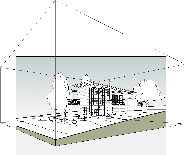
FIGURE 13.6 A toposurface appears as a solid in a 3D view only if a section box is used.
You can create a toposurface in three ways: by placing points at specific elevations, by using a linked CAD file with lines or points at varying elevations, or by using a points file generated by a civil-engineering application. You’ll create a site from an imported CAD file in the first exercise.
A common workflow you may encounter when creating the topography context involves the use of CAD data generated by a civil engineer. In this case, the engineer must create a file with 3D data. Blocks, circles, and contour polylines must exist in the CAD file at the appropriate vertical elevation to be used in the process of generating a toposurface in Revit Architecture.
Building Pad
 A building pad in Revit Architecture is a unique model element that resembles a floor. It can have a thickness and compound structure, it is associated with a level, and it can be sloped using slope arrows while you’re sketching its boundary. The building pad is different from a floor because it will automatically cut through a toposurface, defining the outline for your building’s garden level or basement.
Exercise 13.1: Model a Toposurface
In the following exercise, you will download a sample DWG file with contour polylines. You must link the file into your Revit Architecture project before creating the toposurface. Here are the steps:
- Create a new Revit Architecture project using the Architectural Template.
- Download the file
c13-ex13.1Site.dwgfrom this book’s web page, www.sybex.com/go/revit2015essentials. - Activate the floor plan named Site in the Project Browser.
- Go to the Insert tab in the ribbon, and click the Link CAD button. Select the
c13-ex13.1Site.dwgfile, and set the following options:- Current View Only: Unchecked
- Import Units: Auto-Detect
- Positioning: Auto – Center To Center
- Place At: Level 1
- Click Open to close the dialog box and complete the insertion of the CAD link. Open a default 3D view to examine the results (Figure 13.7).
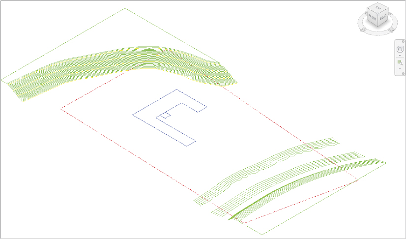
FIGURE 13.7 Linked CAD file as seen in a 3D view
- Click the Toposurface button on the Massing & Site tab in the ribbon.
- In the Tools panel on the Modify | Edit Surface tab, select Create From Import and then choose Select Import Instance.
- Click the linked CAD file, and the Add Points From Selected Layers dialog box appears (Figure 13.8).
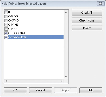
FIGURE 13.8 Select only the layers containing 3D contour information.
- Click the Check None button, and then select the layers C-TOPO-MAJR and C-TOPO-MINR.
- Click OK to close the dialog box. Revit Architecture may take a few seconds to generate the points based on the contour polylines in the linked file, but they will appear as black squares when they have all been placed.
- If you want to use fewer points to define the toposurface, click the Simplify Surface button in the contextual ribbon, and enter a larger value such as 1′-0″ (300 mm), and click OK.
- Click the Finish Surface button in the contextual ribbon to complete the toposurface. Change the visual style of the view to Consistent Colors to examine your results.
Upon completion, your toposurface should resemble c13-ex13.1end.rvt file, available for download from the book’s web page.
Exercise 13.2: Create a Building Pad
The process to create a building pad is virtually identical to that of creating a floor. Let’s run through a quick exercise to create a building pad in a sample project:
- Download the file
c13-ex13.2start.rvtfrom this book’s web page and open it. - Activate the floor plan named Site in the Project Browser. You see an existing topographic surface and a property line. Notice that reference planes were created to demarcate the required zoning setbacks from the property line. Foundation walls have been created in these reference planes.
- Activate the Cellar floor plan from the Project Browser.
- Go to the Massing & Site tab in the ribbon, and click the Building Pad button.
- In the Properties palette, change the Height Offset From Level value to 0.
- Switch to Pick Walls mode, if not already selected, in the Draw panel of the contextual ribbon, and then click the inside edges of the four foundation walls. You can use the Tab+select method to place all four lines at once.
- Click the Finish Edit Mode button in the contextual ribbon to complete the sketch.
- Double-click the section head in the plan view to examine your results. Notice that the top of the building pad is at the Cellar level and the poche of the topographic surface has been removed in the space of the cellar (Figure 13.9).
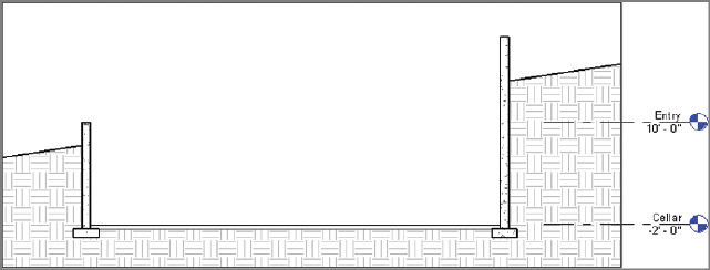
FIGURE 13.9 This section view illustrates how the building pad adjusts the extents of the topographic surface.
Upon completion, your building pad should resemble c13-ex13.2end.rvt file, available for download from the book’s web page.
Performing Quality Control on Your Model: Keeping an Eye on File Size
You can take several measures to ensure that your model is a smooth-running and efficient machine. From time to time, ideally after major project milestones, someone on the project team should oversee the following steps to manage your model’s file size and number of warnings.
Watch the size of your file. It’s a good metric for general file stability. A typical Revit Architecture file size for a project in construction documents will be between 100 MB and 250 MB (250 MB is on the high side of file sizes). Beyond that, you will find that the model will be slow to open and hard to rotate in 3D views, and other views, such as building elevations and overall plans, will also be slow to open.
Should your file become large or unwieldy, you have several ways to trim the file down and get the model lean and responsive again.
Purging Unused Families and Groups
On the Manage tab is a command called Purge Unused. This command removes all the unused families and groups from your model by deleting them. Many times in a design process you will change window types or wall types or swap one set of families for another. Even if those elements are not being used in the project, they are being stored in the file, and therefore when the file is opened, they are being loaded into memory. Depending on the stage of your project, you should periodically delete these elements from the model to keep your file size down.
 Select the Manage tab, and choose Purge Unused on the Settings panel. Depending on the size of your model and how many families you have loaded, it might take Revit Architecture a few minutes to complete this command.
After Revit Architecture is done thinking, it will provide you with a list of all the families and groups in the file that are not actively in a view (Figure 13.10). At this point, you have the option to select the elements you want to delete or to keep and remove the rest.
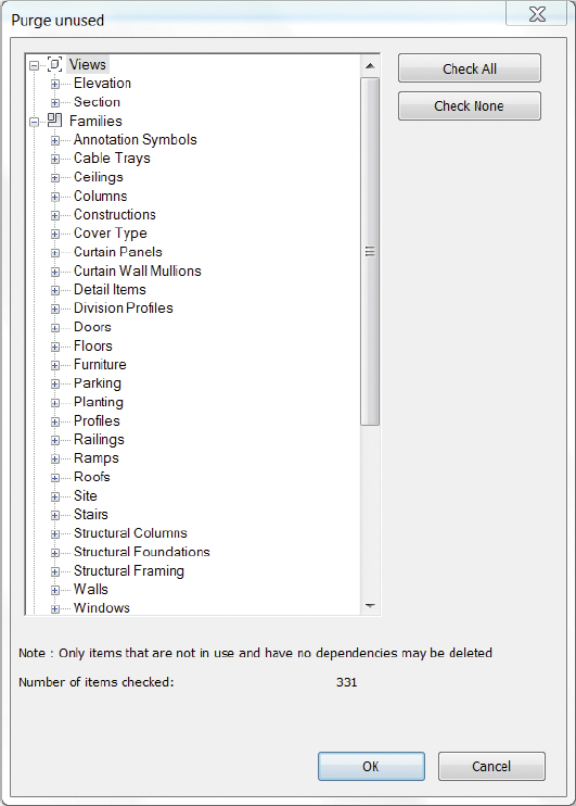
FIGURE 13.10 The Purge Unused dialog box
We don’t recommend you use this command in the early stages of design, mainly because your file size won’t be that large early on and purging at this stage would eliminate any preloaded families that you might have included in your template. During schematic design and design development, you are typically going through design iteration and will likely be adding and removing content regularly. It can become a hassle to have to constantly load or reload families into the model. If your model is not suffering from performance issues or the file size isn’t unruly, it’s not necessary to perform a Purge Unused command.
Managing Links and Images
 Another way to manage your project’s file size is to remove all unused linked files and raster images from your model. If you’ve linked CAD files from your civil engineer or other consultants and no longer need them as a reference in your model, removing them will also unload that stored data from your model. In addition, if you’ve imported raster images into your project, deleting them can significantly reduce your file size. It is good practice to periodically remove these types of files from your model, especially after major deadlines, if they are not actively being used in your project.
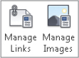
To access these options, find the Manage Project panel on the Manage tab. Notice the Manage Links and Manage Images tools. These two commands allow you to remove any linked CAD files, Revit files, Point Cloud files, or DWF files, as well as any raster images not required for your project. Click Manage Links to remove any unwanted files, browse to the appropriate tab, select the file to delete, and click Remove. Manage Images works similarly; click Manage Images, highlight the image you want to remove, and click Delete.
Cutting Down on the Number of Views
The ability to quickly create views in a model is one of the fast and easy benefits of using Revit Architecture. This ability can also be a detriment, though, if it is not managed. Beyond the hassle of having to sort through many views to find the one you need, having too many views in Revit Architecture can also impact your performance and file size.
Obviously, a number of views are needed in the model to create the construction documentation. In addition, you will find yourself creating views to study the design, deal with model creation, or view the building or project from a new angle. These types of working views will never make it to the sheet set, and some will be used only for brief periods.
Dealing with Warnings
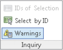 An important way to troubleshoot your model is to use the Review Warnings tool. This tool will do very little to affect your overall file size, but it will alert you to problems in the model. Warnings should regularly be addressed to ensure file stability. To open the Review Warnings dialog box, shown in Figure 13.11, click the Warnings button on the Inquiry panel of the Manage tab. The dialog box lists all warnings still active in your project file.
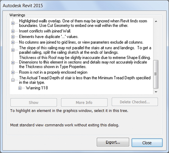
FIGURE 13.11 The Warnings dialog box
![]() Errors and warnings are all essentially types of issues Revit Architecture has when it tries to resolve geometry, conflicts, or formulas that do not equate. Things that appear in this dialog box include instances of multiple elements sitting directly on top of each other, thereby creating inaccurate schedule counts; wall joints that do not properly clean themselves up; wall and room separation lines overlapping; stairs that have the wrong number of risers between floors; and so on. This dialog box shows you all the times the yellow warning box appeared in the bottom-right corner of the screen and you ignored it. Errors that go unchecked can compound to create other errors and can also lead to inaccurate reporting in schedules or even file corruption. Check the Warnings dialog box regularly as part of your periodic file maintenance, and try to keep the number of instances to a minimum.
Errors and warnings are all essentially types of issues Revit Architecture has when it tries to resolve geometry, conflicts, or formulas that do not equate. Things that appear in this dialog box include instances of multiple elements sitting directly on top of each other, thereby creating inaccurate schedule counts; wall joints that do not properly clean themselves up; wall and room separation lines overlapping; stairs that have the wrong number of risers between floors; and so on. This dialog box shows you all the times the yellow warning box appeared in the bottom-right corner of the screen and you ignored it. Errors that go unchecked can compound to create other errors and can also lead to inaccurate reporting in schedules or even file corruption. Check the Warnings dialog box regularly as part of your periodic file maintenance, and try to keep the number of instances to a minimum.
Notice that the Warnings dialog box has an Export feature. Use this feature to export your error list to an HTML file so you can read it at your leisure outside the model environment (Figure 13.12). You can also pull this list into a Microsoft Word or Excel document so you can distribute the errors across the team to be resolved.
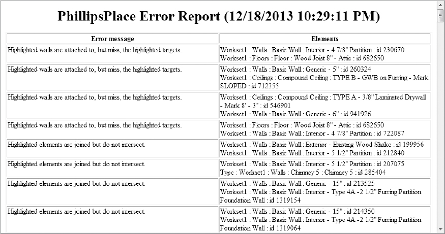
FIGURE 13.12 Exporting errors and warnings
In the example shown in Figure 13.12, using the Phillips Place model, the file has 118 errors and warnings. How many errors in a file are too many? Much of that depends on your model, your computer’s capabilities, the error types, and your deliverable. For instance, if you are delivering a BIM model to your client or to the contractor, you might have a zero-error requirement. In that case, no errors are acceptable. If you are still actively in the design phase of the project, however, you will always have some errors—it is an inescapable part of the iteration process. As you refine the drawings, errors will be resolved; and as you add new content to the model that is in need of resolution, new errors will be created. If you are not worried about a model deliverable, you can get away with having fewer than 1,000 errors in the project without too much trouble. That said, the cleaner the model, the smoother it will run.