2
Block diagrams
A block diagram portrays the general construction of an electronic device or system. A block diagram can also provide a simplified version of a circuit by separating the main parts and showing you how they are interconnected.
A simple example
Figure 2-1 is a block diagram of a device that converts alternating current (AC) to direct current (DC). The terminal at the left accepts the AC input. In sequence going from left to right, the electricity passes through the transformer, the rectifier, and the filter before arriving at the output as DC. In this case, the lines that connect the blocks do not have arrows because readers will naturally assume that the flow goes from left to right. The input terminal resides at the left-hand end of the diagram, and the output lies on the extreme right. In more complicated block diagrams, the interconnecting lines may include arrows to show which block affects which, or to indicate the general direction of signal flow when it might not otherwise be clear.
Functional drawings
Engineers and technicians employ block diagrams in various ways. Commonly, block diagrams indicate the interconnections between small circuits in a larger device, or between diverse devices in a large system. When drawn as shown in Fig. 2-1, block diagrams can also be called functional diagrams because they reveal the basic functioning of the electronic circuit. The functional diagram offers a simplistic explanation of how the device operates; it can lead to more detailed information provided by a schematic diagram.
Someone who wants to draw a schematic diagram for a complex electronic circuit designed from scratch can start with a block diagram. This diagram will show all of the circuit sections (stages) needed to arrive at a functioning device, but none of the internal details of those stages. Then the designer will develop schematic diagrams of circuits that can fill each block and serve the appropriate function in the overall system. The first block in the diagram will then be replaced by the schematic diagram of the circuit it represents. The engineer or technician will move through the blocks according to functional order, creating schematic diagrams that can be used to build each stage in the system. As soon as the final block has been filled in with a schematic for the applicable stage, the comprehensive schematic is complete, and a total (but so far only theoretical) system design is portrayed in detail.
Another way of using block diagrams starts with a finished schematic diagram. Imagine that the schematic is complicated, and that the equipment whose circuit it represents does not work properly. Although schematic diagrams can describe the functioning of an electronic circuit, they are not as clear and basic as a functional block diagram for that purpose. In the absence of a preexisting block diagram, a technician would have to start with the schematic, laboriously identify each stage in the system, and then draw the entire system diagram in block form. When finished, the block diagram would reveal how each stage interacts with the others. Using this method, one or more stages could be identified as a possible trouble area. Then the technician would refer to the original schematic and conduct tests in specific areas, based on his or her knowledge of how each stage works at the component level.
Tip
In practice, you’ll often encounter block diagrams. If presented without accompanying schematics, a block diagram describes the basic functional operation of an electronic device or system. The block diagram can prove most useful when you don’t need to know the functions of individual components.
We can describe the operation of a specific type of wireless transmitter, say an amplitude-modulated (AM) voice transmitter, such as the type found in Citizens Band (CB) radios, by means of a block diagram. This diagram will apply to most other AM voice radio transmitters. Of course, no two transmitters built by different manufacturers are exactly alike, but all of them contain the same basic circuit sections as far as functionality goes. One type of oscillator might work differently from another type, but they all do the same thing: generate a radio-frequency (RF) signal! When we need to know, or portray, individual differences between circuits that do essentially the same things, then we need schematic diagrams.
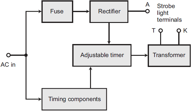
The block diagram in Fig. 2-2 illustrates the various parts of a strobe light circuit. Let’s go through the diagram block by block to understand how it works. The input signal enters at the left; it’s utility AC, such as we get from a standard wall outlet. In the United States and some other countries, this AC has a nominal voltage of 117 volts (V) and a frequency of 60 hertz (Hz), where “hertz” means “cycles per second.” (In some countries, the voltage is about 234 V, and in some countries, you’ll find a frequency of 50 Hz rather than 60 Hz.) The input AC goes to a fuse, and also to a combination of components that provide timing. The top path, where the fuse is located, leads to a diode-type rectifier, and the rectifier output passes directly to one terminal of the three-terminal strobe lamp. The rectifier also outputs to an adjuster that provides a variable flash rate for the lamp. The output from that adjuster goes to a transformer, which provides the remaining two outputs required to operate the lamp.
FIG. 2-2. Block diagram of a circuit designed to provide power to a strobe light. Arrows show the direction of elecricity flow.
Current and signal paths
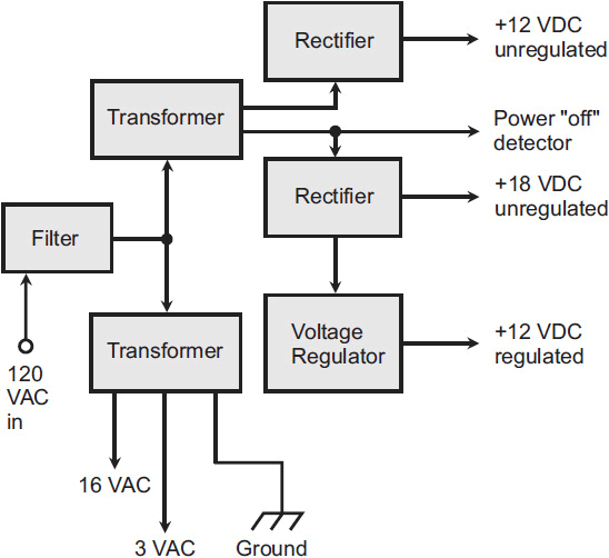
Figure 2-3 shows a power supply that produces several different voltage outputs. As you go through this diagram from left (the input) to the bottom and the right (the outputs), note that the circuit is powered with 120 volts AC (120 VAC), quite close to the nominal 117 VAC commonly found at utility outlets in the United States. The input AC goes through a filter and then splits into two paths. Part of the AC goes to the “lower” transformer that provides 16 VAC and 3 VAC output, along with a ground connection.
From the filter, the input voltage gets fed to another transformer that derives the voltages to be converted to DC electricity. One output of the transformer goes to a rectifier that provides 12 volts DC (12 VDC) without any voltage regulation. The other transformer output goes to a separate rectifier that provides 18 VDC, also unregulated. This transformer output also serves as a diagnostic detector for a power “off” condition. That line is further tapped to join with the output of the voltage regulator to provide 12 VDC with voltage regulation.
Tip
Block diagrams are comparatively easy to draw, comprising squares or rectangles along with interconnecting lines (sometimes with arrows). More sophisticated block diagrams also include triangles to represent circuit blocks built around specialized amplifiers constructed within integrated circuits (ICs), also known as chips.
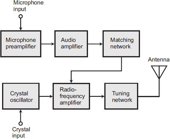
Figure 2-4 is a block diagram of an AM radio transmitter. The microphone preamplifier stage goes to the input of the audio amplifier stage (note the direction of the arrow). The output of the audio amplifier goes to the matching network, which in turn goes to the RF amplifier section. The crystal oscillator is also connected to the RF amplifier section, whose output leads into the RF tuning network. Only one connection exists between the audio section of the circuit and the RF section: the one between the matching network and the RF amplifier. This block diagram, with its arrows, tells us not only how the components of the system connect to one another, but also the sequence of events or direction of signal flow.
Flowcharts
Block diagrams can describe the functioning of electronic circuits, but in the world of computers, another form of diagramming is sometimes used to portray the functioning of a program. This system is called flowcharting. A flowchart resembles a block diagram, except that the symbology applies to the sections of a computer program, an intangible thing (as opposed to an electronic circuit, a tangible thing). A flowchart provides a graphic representation of the logical paths that a computer will take as it executes a particular program. Flowcharts are often prepared in conjunction with specifications, and are modified as the requirements change to fit within the constraints of the computer system.
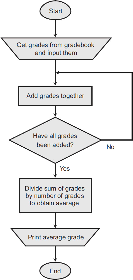
For complex problems, a formal written specification might be necessary to ensure that everyone involved understands and agrees on what the problem is, and on what the results of the program should be. To illustrate this concept, let’s suppose that a teacher wants to write a computer program that will determine a student’s final grade for a course by calculating an average from grades the student has received over a certain period of time. The teacher will supply the grades to the program as input. Only the average grade is needed as an output. Now, we can make an orderly list of what the program has to do:
• Input the individual grades.
• Add the grade values together to find their sum.
• Divide the sum by the number of grades to find the average grade.
• Print out the average grade.
We can prepare a flowchart of the program, as shown in Fig. 2-5. As we can see, the flowchart graphically presents the structure of the program, revealing the relationship between the steps and paths. When the flow of control is complicated by many different paths that result from many decisions, a good flowchart can help the programmer sort things out. The flowchart can serve as a thinking-out tool to understand the problem and to aid in program design. The flowchart symbols have English narrative descriptions rather than programming language statements because we want to describe what happens, not how it happens. At a later stage, if formal flowcharts are required for documentation, the flowchart can contain statements in a programming language. These flowcharts might prove helpful to another person who at some future time wants to understand the program.
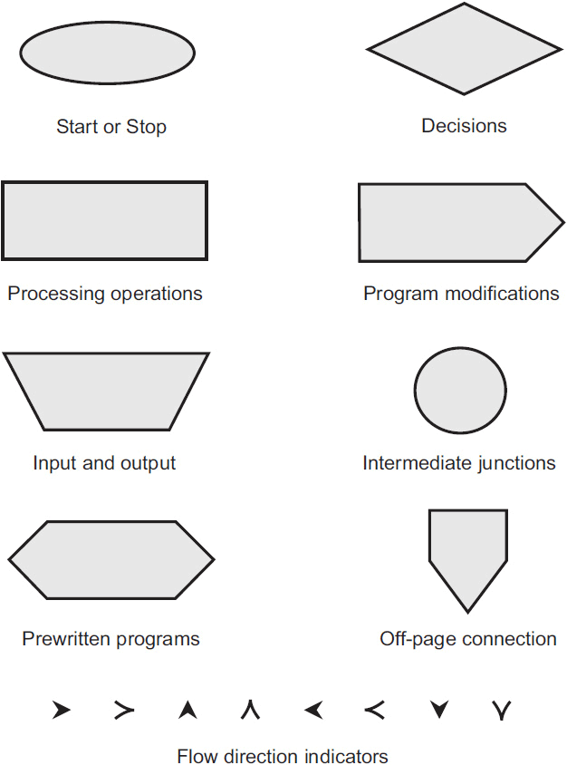
It takes a lot of time to conceive and draw up a formal flowchart, and modifying a flowchart to incorporate changes, once a program has been written and its flowchart composed, can prove difficult. Because of these limitations, some programmers will shy away from the use of a flowchart, but for others, it can provide valuable assistance in understanding a program. In order to promote uniformity in flowcharts, standard symbols have been adopted, the most common of which are shown and defined in Fig. 2-6.
The normal direction of processes in a flowchart runs from top to bottom and from left to right, the same way as people read books in most of the world. Arrowheads on flow lines indicate direction. The arrows can be omitted if, but only if, the direction of flow is obvious without them.
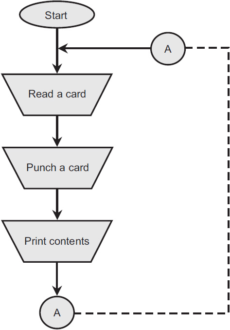
Figure 2-7 is a flowchart for a program that duplicates punched cards, and at the same time prints the data on each card. Keep in mind that this particular “beast” is of historical interest only! (Were you born long enough ago to remember punch cards for inputting programs to computers? I recall using them, all the way back in the 1970s, when I attended the University of Minnesota. I guess that little factoid dates me, doesn’t it?)
FIG. 2-7. Flowchart for a program for duplicating punched cards. The circles labeled A represent the inflow and outflow points in the feedback loop shown by the dashed line.
Let’s trace the flow of the program through Fig. 2-7. The program begins at the “Start” oval at the top and proceeds in the direction of the arrows. In the first box below “Start,” the program reads a card. Then the program punches the card’s contents (data) as holes in a blank piece of heavy paper and sends the data to a printer. The program then goes back along the dashed line to the top and reads the next card. The circles marked A represent inflow and outflow points. In this case, they’re superfluous, but in complicated flowcharts, they can be useful when it would create a mess to include all the applicable dashed lines. The program repeats itself as long as it has cards to read and punch.
In a sophisticated flowchart, we might see several different symbols of the sort shown in Fig. 2-6, and maybe even all of them. Oval boxes show start or stop points. Arithmetic operations go in rectangular boxes. Input and output instructions go in upside-down trapezoids. If we want to show a program that someone wrote earlier within the context of a larger flowchart, we don’t necessarily have to draw the flowchart for the inside program. Rather, we might represent the entire program as a flattened hexagon. If a box indicates a decision, we use a diamond shape. A five-sided box portrays a part of the program that changes itself. A small circle identifies a processing junction point. Such a point in the program can go to several places. A small five-sided box, which has the shape of the home plate on a baseball field, shows where one page of a flowchart connects to the next, if the entire flowchart has more than one page. The intermediate junction and off-page connection points are labeled with numbers and letters to let readers know that all like symbols with the same character inside are meant to be connected together. Arrows indicate the direction of the flow.
Process paths
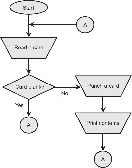
Returning to the flowchart for duplicating punched cards (Fig. 2-7), suppose that you want to change the card-punching program so that the computer skips blank cards and duplicates only those cards with some holes in them. Because the computer must make a decision about each card, you’ll need to include a decision block in the flowchart. Figure 2-8 shows the result.
FIG. 2-8. Example of a flowchart that includes a decision block (the diamond). The circles labeled A all represent a single junction point through which data flows in the directions shown by the arrows.
Except for the decision block, Fig. 2-8 shows the same process as Fig. 2-7 does. The program begins in the “Start” oval at the top and then goes to the block marked “Read a card.” From there, the program moves on to the decision block labeled “Card blank?” If the answer is “Yes,” the program proceeds to the connection circle marked “A” and back to the top to read the next card. If the answer is “No” (the card has holes in it), the program instructs the hardware (the physical components of the computer) to punch a duplicate card and print its contents. Then the program goes to another circle marked “A” and back to the starting point.
Figure 2-8 is a simple flowchart, showing a process that uses only input and output devices and that does no calculations. Most programs and flowcharts involve more complicated processes.
The field of microcomputers uses many different types of diagrams that deal mostly with software (the operating systems and programs) rather than hardware (the physical components). From a purely electronic standpoint, functional diagrams abound and are usually more numerous than the schematic diagrams in the computer world. From an understanding standpoint, block diagrams can serve to display machine functions in general, but hardware maintenance and repair procedures require well-defined schematic drawings. Computers take advantage of the latest state-of-the-art developments in electronic components and are relatively simple from this standpoint, especially when you consider all they can do. However, from a pure electronics standpoint and as far as schematic diagrams are concerned, computers are highly complex; it would take many pages of schematics to represent even the most rudimentary computer.
Summary
Block diagramming can help you understand the general functioning of electronic circuits. Block diagrams are easy to draw, usually requiring only a marking instrument, some paper, and a straightedge (or a vector graphics computer program and a little bit of training on it). Schematic diagrams, in contrast, need more tools and can, in some cases, take many hours to render in a form that people can easily read and interpret.
