
The development of the CAN bus (controller area network) began in 1983 at Robert Bosch GmbH as a way to standardize communications between components. Prior to this, automotive ECUs (engine control units) each had their own proprietary systems, which required a lot of point-to-point wiring. In 1986, Bosch released the developed CAN protocol at the SAE Congress (Society of Automotive Engineers). 1 In 1991 the CAN 2.0 protocol was published by Bosch and was adopted in 1993 as the international standard (ISO 11898). Since then, automobiles have used the protocol for communication and to reduce wiring harness sizes by use of the bus.
Having CAN bus capability in the STM32 device makes it attractive for automotive or control applications. Even though this chapter’s demonstration will model the control system of a car, it will become apparent that the CAN bus need not be restricted to automotive applications. Model aircraft, drones, and model railway systems are just some of the potential hobby applications.
The CAN Bus
Imagine that you have the task of reducing the bulk of the wiring harness for a new car model to be manufactured. This vehicle has several electronic control units at the front, center, and rear of the vehicle, and each requires communication with the others, including the master control unit, which is perhaps located behind the dashboard. How do you reduce the number of wires needed?
Almost since the beginning, manufacturers have reduced the wiring by using the metal body of the car as the negative terminal for the battery-return current. However, the control of the load has been traditionally handled by switching the +12-volt power on and off to the brake or signal lamp, for example. This requires a separate wire in the harness for each load to be controlled.
Additionally, with electronic control units, you now must also supply lines of communication. With units that communicate with most or all of the other units, the number of wired connections explodes.
The solution to the harness problem is to adopt a bus system. Every control unit that communicates is attached to the same bus and sends messages over the bus. With this configuration, you need the following:
a power line (+12 volts)
one or a pair of bus signal lines
a negative return path for power (metal car body)
If we assume a pair of bus signal lines then we only need three wires to power and communicate with all devices connected to it. Figure 18-1 illustrates a hypothetical bus system and power connections.

Figure 18-1 Hypothetical automotive bus system
Using this arrangement, any control unit CUx can communicate with any other control unit. If control unit CU3 is located at the rear of the vehicle, then it could also control light bulbs located at the rear based upon messages passed on the bus. CU3 can switch nearby lamps by switching the +12-volt power with short runs of wire to the unit itself. While automobiles may not do this presently for brake and signal lights, it is technically possible to do so. Sometimes there may be overriding safety concerns—it is important that brake lights don’t fail as a result of software errors, for example. The bus design does, however, allow widespread communication and provides control with lighter wiring.
Differential Signals
High-speed linear CAN bus is defined by the ISO 11898-2 signal format, with an example signal shown in the upper part of Figure 18-2. The signal pair consists of a CAN H (high) and a CAN L (low) line, the latter of which idles near the 2.5-volt level. The idle state is known as the recessive logic level .
The active state of the signal is known in the standard as the dominant logic level . The dominant logic state has CAN H near +5 volts and CAN L near 0 volts. The differential signal is required for high-speed communication with noise immunity. The state of the logic is determined by how much CAN H differs from CAN L (V diff in the figure). To prevent signal reflections, the high-speed linear bus is terminated at each end with 120 Ω of resistance.
The lower half of Figure 18-2 shows the single-ended driver signal. For our purposes, this is the signal that leaves the STM32 and enters the driver chip. From a driver-signal perspective, the dominant logic level is low, while the recessive level is high. High can be 5 volts or 3.3 volts, depending upon the logic levels being utilized.
The driver circuit requires only one wire, but this limits it to short runs because of signal reflections and noise. The differential bus design, on the other hand, allows for longer runs of several meters.
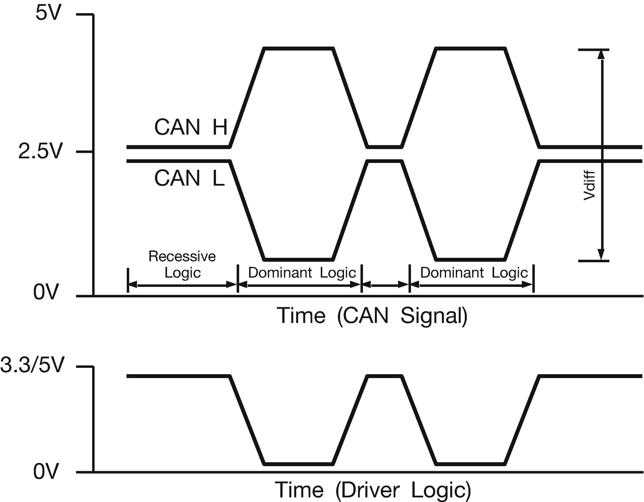
Figure 18-2 High-speed linear CAN bus and driver-signal formats
Dominant/Recessive
Recessive and dominant signal forms have already been described for the CAN bus. But what is the significance of these terms, recessive and dominant?
A recessive signal is a relaxed form of the signal. In differential signalling, the CAN H and CAN L signals reach their idle state through a resistive network. This is the natural state for the signal at rest. For the single-ended driver signal, it represents a high level that is achieved by a pull-up resistor . This too is the rest state of the driver signal.
A dominant signal , however, is driven from its rest state to its active state through the work of transistors. For the differential bus signals, the CAN H line is pulled high by a high-side transistor. Simultaneously, the CAN L line is pulled low by a low-side transistor in the on state. The driver signal likewise goes from a pulled-high state to a pulled-low state by a low-side transistor in conduction. In other words, the driver signal is driven low by an open-drain transistor in the active state.
The differential bus is like the single-ended driver signal except that there are mirror copies of each signal. They both idle near the middle when at rest (recessive) but are pulled away from each other when made active (dominant).
Now imagine two units driving a common bus. It is easiest to think in terms of the single-ended driver signal, but do realize that the principle also applies to the differential bus. Table 18-1 illustrates a truth table for two drivers connected to the bus.
Table 18-1 Truth Table for Bus Arbitration
Driver 1 | Driver 2 | Bus Result | Description |
|---|---|---|---|
recessive | recessive | recessive | Bus is idle |
dominant | recessive | dominant | Dominant state |
recessive | dominant | dominant | Dominant state |
dominant | dominant | dominant | Dominant state |
Essentially, the bus state becomes the logical OR of all drivers connected to the bus. When any driver applies the dominant bit state, the bus takes the dominant state. Only when no driver is driving the bus does the bus remain in the recessive state . It should be obvious now why the states are named recessive and dominant .
Bus Arbitration
In bus systems such as I2C, there is one master and multiple slaves. The slave device is not allowed to speak until requested by the master. In multi-master I2C there has to be an arbitration procedure that works out which master is allowed to proceed in the event that two or more devices collide trying to transmit at the same time. This tends to be a complicated problem that can lead to bus lockups.
The CAN bus, on the other hand, permits every connected device to speak. Thus, collision avoidance also requires arbitration. The way it is done for the CAN bus is unique and relies on the principle of recessive and dominant states. Figure 18-3 illustrates how the recessive and dominant bits interact.

Figure 18-3 CAN bus arbitration
Arbitration proceeds as follows:
Driver 1 and Driver 2 start a communication at the same time by sending a message ID.
The first two bits are dominant (zero), so all devices connected to the bus see the two zeros.
Driver 1 sends the third bit as dominant (zero), while Driver 2 attempts to send a recessive (one) bit. The bus sees only a dominant bit (zero).
Driver 2, realizing that its recessive bit was “stomped on,” backs off since it has lost the arbitration process. Driver 1’s message was not harmed and can proceed.
Arbitration illustrates the purpose of the dominant bits. Each device continues to transmit while listening to the bus. If any device sends a recessive bit but reads it back as a dominant bit, it means that arbitration for the bus was lost. The losing device(s) then cancel their transmission, allowing the winner to proceed with the message unharmed.
Synchronization
The arbitration procedure just presented is a simplified explanation for a more complicated reality. How do several transmitters communicate in lockstep?
Before the message ID is transmitted, there is an SOF bit (start of frame) sent. It is a dominant (zero) bit, so no listening device will miss the start-of-message indication that it is. Thus, when the SOF bit is received, the sending device on the same bus can cancel an attempt to send a message if it is not ready. If the device is ready, it synchronizes its clock and attempts to send the message ID.
After the SOF bit, each message begins with a message ID. Depending on the version of the protocol, the message ID is 11 or 29 bits in length. The arbitration procedure determines who will win based upon the message ID being sent. Recall that dominant bits win over recessive bits. Consequently, a message ID value of all zero bits is the highest priority message.
Message Format
The basic CAN message format is provided in Table 18-2. There is also an extended format that differs slightly, which the reader is encouraged to research.
Frame field RTR (Remote Transmission Request) has a provision for requesting a transmission from the remote device. When the RTR bit is recessive, this indicates a response from a device. In these messages, the DLC (Data Length Code) is not used, and no data is sent.
The field IDE (Identifier extension bit) identifies whether an extended ID message format is used. In this chapter, the demo uses the 11-bit format, using the dominant bit setting to indicate this.
The DLC field indicates the data length (in non-RTR response) in bytes. The DLC field is then followed by the indicated number of data bytes.
Near the frame end, the CRC (Cyclic Redundancy Check) field exists so that garbled messages can be disregarded.
Finally, at the frame’s end is an ACK bit field. This bit is transmitted as a recessive bit (1) so that if any device receives the message with CRC intact, the receiving device will clamp the bus using a dominant state during that bit time. This allows the transmitter to see that at least one device received the message ok. Generally speaking, if one device receives the message ok, then all devices did. Note that all receiving devices are permitted to respond with the ACK simultaneously.
If, on the other hand, no devices received the message, the ACK bit will remain at the recessive state as transmitted. This indicates to the transmitter that the transmission failed. This part of the protocol can make CAN bus driver development a little more difficult because you need at least one other device on the bus to ACK the sent message. The only other way to test the sending of a CAN message is to use an internal loop-back feature of the STM32 peripheral.
Table 18-2 CAN Bus Message Format (Non-extended)
Field Name | Bit Length | Description |
|---|---|---|
SOF | 1 | Start of Frame |
ID | 11 | Message ID/Priority |
RTR | 1 | Remote Transmission Request: 0 for data frames, 1 for remote request |
IDE | 1 | Identifier extension: 0 for 11-bit format, 1 for 29-bit |
Reserved | 1 | Must be 0 |
DLC | 4 | Data Length Code: 0 to 8 bytes |
Data | 0–64 | Transmitted data (DLC sets length) |
CRC | 15 | |
CRC delimiter | 1 | Must be 1 (recessive) |
ACK slot | 1 | Transmitter sends 1 (recessive), receiver(s) respond with 0 (dominant) |
ACK delimiter | 1 | Must be 1 (recessive) |
EOF | 1 | End of Frame: 1 (recessive) |
STM32 Limitation
The STM32 CAN bus peripheral uses SRAM to store messages. Unfortunately, the design of the STM32F103 MCU is such that CAN and USB share the same area of memory. For this reason, CAN and USB cannot be used at the same time.
It is otherwise possible to disable one device and use the other and vice versa, but this doesn’t appear to be practical. For this reason, the demonstration will use the UART for communication.
Demonstration
There is considerably more that could be described about CAN bus protocol and its extensions. The interested reader is encouraged to seek out other books on the subject. The focus of this chapter, however, is to illustrate how to use the STM32’s CAN bus peripheral in ways that are simple enough to get started.
In this demo, we are going to implement three hypothetical EU (electronic units). I’ll refer to them as EU1 through EU3 and avoid the acronym ECU, which is normally known as an engine control unit . The units are:
EU1, dashboard control unit (has UART interface). This provides lamp controls and reads temperature from the rear EU3.
EU2, a rear controller unit responsible for parking, signal, and brake lamps
EU3, a front controller unit responsible for front parking and signal lamps
A full demonstration thus requires three STM32 MCUs. However, if you have two, you can at least partially demonstrate the operation, though three works best. Leave out the front EU2 if necessary. But with the low price of the Blue Pill, why limit yourself to only two units?
Software Build
The software directory for the demonstration is located at the following:
$ cd stm32f103c8t6/rtos/canTake a moment now to recompile it:
$ make clobber
$ make
This will compile three executables:
$ ls *.elf
front.elf    main.elf    rear.elf
UART Interface
EU1 is the main control unit that will simulate what will reside behind the dashboard of our hypothetical vehicle (module main.c). The demonstration is configured for the following serial-port parameters, which must agree with minicom or the terminal program of your choice:
Baud rate: 115,200
Data bits: 8
Parity: None
Stop bit: 1
Hardware flow control: RTS/CTS
See Table 10-1 for the connection details.
Students, please note that hardware flow control requires RTS and CTS wires to be connected to your TTL serial adapter and STM32. Once connected, your terminal program must also be configured to use hardware flow control. If any detail is incorrect, no communication will occur. If the flow control is not operational for some reason, then you may see lost data and garbage.
If the hardware flow control presents issues or your TTL serial adapter lacks the required RTS/CTS signals, change the following source line in main.c from open_uart(1,115200,"8N1","rw",1,1); to the following:
open_uart(1,9600,"8N1","rw",0,0);Later, after recompiling, if there seems to be some data loss, reduce the baud rate even further. Otherwise, the lower baud rate of 9,600 should be alright.
MCU Flashing
There are three MCUs to flash for this demonstration:
EU1: main.c
EU2: front.c
EU3: rear.c
Let’s flash the devices (after the build). You’ll obviously need to hook the programmer up to each device in turn. If you need to reflash these, you will likely need to change the boot0 jumper temporarily.
$ make flash
$ make flash_front
$ make flash_rear
Demo Bus
To make things easier, this demonstration uses a short but single-wire CAN bus (SWCAN) using a 4.7-kohm pull-up resistor. In this configuration, each STM32 MCU has its CAN_RX and CAN_TX lines tied together and connected to the common bus line. Normally, these connections would go to a CAN bus driver chip like PCA82C251, with separate RX and TX connections. Search for “PCA82C251 datasheet PDF” for more details about the chip.
When wiring the demo, make special note of the fact that the main.c MCU uses different CAN connections from the others. This was done so that the 5-volt-tolerant UART connections could be used, permitting 5-volt USB-TTL serial adapters to be used. See Figure 18-4.
Resistor R1 is a required pull-up resistance necessary to establish the recessive state. Since the MCU is a 3.3-volt device, our recessive state will be near +3.3 volts. Because of the pull-up resistor, we configure the GPIO for CAN_TX with GPIO_CNF_OUTPUT_ALTFN_OPENDRAIN (emphasis on open drain).
The other MCUs share the bus and the grounds. Don’t forget to tie those grounds together. Any message sent by one MCU is received by all of the others.

Figure 18-4 Demonstration CAN bus hookup
The LEDs are representative of automotive lamps for signal, brake, and parking lights. The rear signal lamps operate as both brake and signal lamps.
Session Run
The demo can be set up on a breadboard. Figure 18-5 shows the author’s own arrangement, with the power supplied by a MB102 PCB. This provides +5 volts to each of the Blue Pill +5-volt inputs, resulting in each Blue Pill’s on-board regulator supplying +3.3 volts to the remainder of the system.
In the center of the photo, you can see the SIP9 resistor array I used for the 220-ohm LED resistors. These single inline package (nine pins) arrays conveniently replace up to nine individual resistors. Pin 1 of the SIP9 resistor is common and goes to the +3.3-volt supply line. To turn on an LED, the connected GPIOs sink the current to ground. If not using the SIP9 part, simply use individual resistors as shown (R2 to R9).
The top of the photo shows the USB-UART device cable and connections to the top MCU (running firmware main.c). This represents the in-dash controller EU1. The bottom MCU is the rear EU3 unit running firmware rear.c.
The LEDs are arranged with the front automotive lamps toward the top and the rear lamps toward the bottom of the photo. The outer green LEDs represent the parking lights. The inner yellow LEDs represent the front turn signals, while the rear red LEDs represent the red turn signals and brake lights.
The single-ended CAN bus is located just to the right of the LEDs, with mostly white DuPont wires connecting the CAN_RX and CAN_TX from each MCU. Within that mess of wires is one 4.7-kohm resistor pulled up to +3.3 volts.
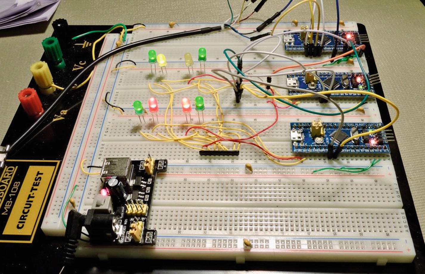
Figure 18-5 Breadboard setup of CAN demo
Once everything is ready, connect your USB-TTL serial device to your PC and start minicom (or equivalent). Once that is ready, power up your breadboard. The main MCU should respond to your serial link as follows:
Welcome to minicom 2.7OPTIONS:Compiled on Sep 17 2016, 05:53:15.Port /dev/cu.usbserial-A703CYQ5, 20:38:01Press Meta-Z for help on special keysCar simulation begun.Menu:L - Turn on left signalsR - Turn on right signalsP - Turn on parking lightsB - Activate brake lightsLower case the above to turn OFFV - Verbose mode (show received messages)CAN Console Ready:> _
The serial link shows a menu allowing you to control various functions of your hypothetical vehicle. If things are working correctly the front and rear MCU on-board LEDs (PC13) should flash about once per second. If you see it blink twice and stop, this indicates a bus connection problem. I experienced this problem when I forgot that CAN GPIOs are different from the main and the front and rear units. Recheck your wiring.
Press a capital “P” to turn on the parking lights. If all went well, your parking lights are now lit, and the console also returned a temperature:
CAN Console Ready:
> P
> Temperature: +24.73 C
>
The temperature was sent to the main unit from the rear unit. To turn the parking lights off, press a lowercase “p.” The parking lights should go dark immediately.
If you now press capital “B,” the brake lights should come on (red in my setup). Pressing lowercase “b” turns them off again.
Press capital “L” or “R” to turn on the left or right turn signals, respectively. Notice that the front and rear signals blink in unison even though controlled by two separate MCUs. Press the lowercase “l” or “r” to turn the signal off again. You can also turn on four-way flashers by enabling left and right.
Last of all, enable a turn signal—say, left—by pressing capital “L.” Then, press capital “B” to enable the brake lights. Now the left turn signal blinks, but the right rear remains lit to indicate a brake light. Turning the turn signal lamp off should leave the two rear brake lights lit.
CAN Messages
The messages are mainly sent from the main EU1 to the front and rear units. After each lamp request, the main unit also sends a message to the rear requesting a temperature (it sets the RTR bit to request a reply). When the rear unit receives a message with the RTR flag true, it takes the temperature and transmits it to the bus. All others can read this message, but only the main unit uses the information.
The other messages are sent to enable/disable a given lamp. To allow the signal lamps to flash in unison, there is also a flash message sent.
Synchronicity
When the signal lamps are flashing, they look very synchronized to the human eye. But just how synchronized are they? Using an oscilloscope, the turning on and off of a signal lamp varied by about ±850 μsec and changes over time. All MCUs receive the message into their peripherals at the same time, but FreeRTOS does preemptive scheduling. Since 1-ms ticks are being used, timing could be off by up to 1 ms.
What if you need greater accuracy for a factory control application? One approach would be to increase the timer tick frequency (reducing the time slice). Other improvements are possible in the application software. For example, the ISR routine could notify a waiting task. There is no single answer to this problem. It often comes down to how important the issue is and how much effort you are willing to expend to obtain it.
Summary
This chapter has focused on introducing some CAN bus concepts and a demo circuit. Running the demo proved that it is possible to have near real-time control over other MCUs using short CAN messages. Additionally, it proves the concept of a shared bus where there are no master and slave devices. Finally, it is seen that the STM32 is capable of applying CAN communications in both single-wire or differential bus modes (differential with the help of a driver chip).
Because of the size and complexity of this project, the software for this demo will be described in the next chapter.
Bibliography
CSS Electronics. 2018. “CAN Bus Explained—A Simple Intro.” Accessed January 13, 2018. https://www.csselectronics.com/screen/page/simple-intro-to-can-bus/language/en .