PROJECTS
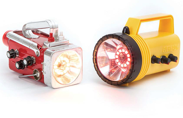
Million Color HSL Flashlight
Million Color HSL
Flashlight
Written by Dan Rasmussen
Hep Svadja
Bring fun back to the flashlight with Arduino and full-color NeoPixel LEDs

DAN RASMUSSEN
is an avid collector, fixer, and hacker of vintage technology. He’s a software engineer who lives in Groton, Massachusetts with his wife and three kids.
WHEN I WAS A KID THERE WERE NO SMART-PHONES, INTERNET, HOME COMPUTERS, OR ARDUINOS. Sure, we had TV and radio, but—believe it or not—we had fun with flashlights too. They often came with colored lenses, or we made our own with paper or plastic.
These days flashlights are mostly for practical purposes and they usually only make white light. Even high-end flashlights are pretty much the same thing, just super bright and rugged for inspecting the levee during the hurricane. Bright and rugged is great, but a one-button, small, efficient, vanilla light isn’t much fun, is it? Let’s bring the fun back to flashlights.
THE HSL FLASHLIGHT
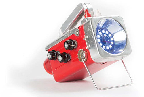
In this project you’ll hack an old-style 6-volt lantern to become a Million Color HSL Flashlight. It’s big and bulky and different. Not quite as bright as some, but it has crazy color that’s so easy to set—just dial your way around the rainbow. Lots of knobs and modes, and you can write code for it too.
Dan Rasmussen
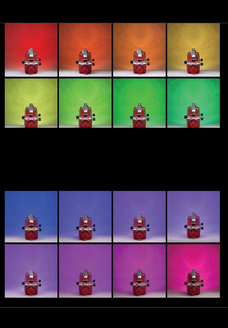
The great thing about HSL is that it’s an intuitive way to select a color. HSL stands for hue, saturation, and lightness. It’s like the 360-degree color pickers available in many computer applications. Our HSL flashlight has a knob for each component: hue selects the color by allowing you to dial your way around the rainbow, saturation selects how deep and rich the colors are (fully desaturated is white, fully saturated is pure color), and lightness behaves like a dimmer.
The flashlight also has a 10-position mode switch, just for fun. The following are the modes I programmed—watch the video on the project page at makezine.com/projects/million-color-hsl-flashlight for a demonstration—but you can always program your own!
- White
- Manual HSL selection
- Auto hue: rotates through the color spectrum (hue knob controls speed)
- Multicolor all-pixel auto-rotate
- Multicolor tri-pixel auto-rotate
- Cylon (aka Larson Scanner)
- Full-color strobe
- Alternate pixel multicolor 180° color alternation
- Half-moon multicolor 180° color alternation
- Alternate pixel-pair multicolor 180° color alternation
HARDWARE
Arduino is a great platform for prototyping your projects. Once you’re ready to build, though, the standard Arduino board is kind of big and its jumper wires provide only fragile connections. So I used the Arduino Pro Mini: inexpensive, very small, and reliable.
I chose Adafruit NeoPixel RGB LEDs because their 12-element ring fits nicely in the reflector bowl in most 6V lanterns, and they come with an Arduino library that’s easy to use.
Old-school “6-volt lantern” flashlights are perfect for this project because the reflector bowl and the battery compartment are both huge. Cool old lanterns are easy to find at flea markets or eBay, but you can also buy new ones.
1. SOLDER HEADERS ON THE ARDUINO
Tack a single pin of the 6-pin header, then check to make sure it’s flush. If not, reheat and adjust.
Now solder the other pins. Rework the tacked pin and add solder if necessary.
2. PROGRAM THE ARDUINO
Download the Arduino sketch HSLFlashlight.ino from the project page, makezine.com/projects/million-color-hsl-flashlight. Connect the Arduino Pro Mini to your computer using your FTDI cable or other compatible device. Open the Arduino IDE software and select the correct board from the Tools → Boards menu. Then open the sketch and verify/compile/upload it to the Arduino.
This tiny board has an LED attached to pin 13. The HSL program will flash it 5 times when it starts. This is a good way to verify that the program has been properly uploaded. (Note that the upload process itself will flash this LED a couple of times.)
Disconnect the Arduino and set it aside.
CAUTION: Some flashlights (especially old ones) use metal reflector bowls, so it’s important to insulate these connections. I simply covered them with small blobs of hot glue.
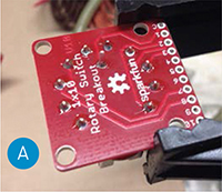
3. WIRE THE 10-POSITION ROTARY SWITCH
The optional breakout board makes it easier to attach and manage the switch’s 11 wires. Tack one pin, make sure it’s flush, then solder all the connections (Figure A).
Cut eleven 8" lengths of 22-gauge wire. Use different colors of wire, or use a light color and mark the wires with a Sharpie to indicate the pin number. Strip about ⅛" of insulation from each end.
I always use black for common/ground and red for raw power. Here I attached black to the common pin, then used different colors for the first few positions (Figure B). After that I used all gray, and marked the other end of the gray wires with dots (4 dots for position 4, 5 for position 5, and so on).
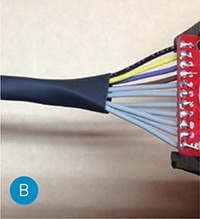
Tame the mess of wires with some heat-shrink tubing. I covered about 60% of the wires.
If you omit the breakout board, solder the wires directly to the 10-position pot.
4. WIRE THE POTENTIOMETERS
Cut three 8" lengths of wire for ground (black), 3 more for Vcc (I used orange), and 3 for analog input (blue). Connect one set of wires to each potentiometer as shown (Figure C). First wrap the wire around the post, then solder it .

Mark the potentiometers as 1, 2, and 3, then mark the other end of each analog input wire with 1, 2, or 3 dots.
5. PREPARE THE NEOPIXEL RING
Cut about 12" each of black, red, and white wire and solder these to the NeoPixel’s power, ground, and signal in pads, routing the wires from the top as shown (Figure D).
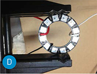
Hot-glue the NeoPixel to the bowl of your flashlight and route the wires through the old bulb hole.
Solder the 300Ω resistor to the other end of your signal wire (white), and insulate with heat-shrink, leaving about ⅛" exposed.
IMPORTANT: Before connecting a NeoPixel strip to power, connect a large capacitor (1,000μF, 6.3V or higher) across the + and – terminals. This prevents the initial onrush of current from damaging the pixels.
6. WIRE THE ARDUINO
Solder a 12" red wire to the Arduino’s raw power input pin; a 12" black wire to the adjacent ground (GND) pin; and a 12" orange wire to the regulated power (VCC) pin.
Solder the 3 blue wires from the potentiometers to the Arduino’s analog inputs A1, A2, and A3 (indicated by the red box in Figure E), matching the dots you marked. A1 is for hue, A2 for lightness, and A3 for saturation.

Solder the 10 signal wires from the switch to the Arduino’s digital inputs 2 through 11, matching position 2 on the switch to Arduino pin 2, position 3 to pin 3, etc. Match position 1 to pin 11.
Solder the 300Ω resistor on the NeoPixel signal wire to digital input 12 (Figure F).
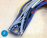
IMPORTANT: The HSL code doesn’t use pin A0, so be sure to connect to the correct 3 pins.
7. MANAGE POWER, GROUND, AND VCC WIRES
Tie all 3 raw power wires (red) together as shown—from the Arduino, the NeoPixel, and the battery pack—then solder and finish with heat-shrink (Figure G).
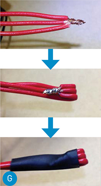
Connect all the VCC power wires (orange) together the same way. Then all the ground wires (black).
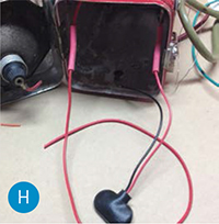
8. INTEGRATE FLASHLIGHT’S ON/OFF SWITCH
Find the wires that go to each side of the switch in your flashlight. Cut them and strip ½" from the ends.
IMPORTANT: Leave the switch in the off position for now.
Cut the red wire from your battery pack and strip ½" from each end. Solder each end to one side of the flashlight switch. Patch in more red wire as necessary to give you some flexibility (Figure H).
9. MOUNT THE ARDUINO IN THE TIC TAC BOX
Empty the Tic Tac box, remove the white plastic dispenser, and cut it down a bit to accommodate the bundle of wires. Then insert the Arduino into the box and seal it with strong tape (Figure I). This will insulate the Arduino from any metal inside the flashlight.

10. TEST
No doubt you’re anxious to see if this thing is going to work! First, center all 3 pots (to be sure the lightness is not all the way down.) Load 4 fully charged NiMH batteries, and power up the electronics by turning on the flashlight switch. Watch for the 5 flashes on the Arduino’s LED. Shortly after that you should see some activity from the NeoPixel ring—no matter where the mode switch is set.
If you see no activity on the Arduino, then there’s probably a short somewhere—turn off the power right away and find the short. In my case it was the NeoPixel ring shorting against the metal bowl of my flashlight.
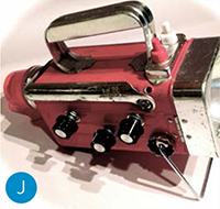
11. MOUNT THE ELECTRONICS IN THE FLASHLIGHT
Drill 3 holes in the flashlight case for the pots and one for the rotary switch, then mount them and attach the knobs. I put the HSL controls on one side and the rotary mode switch on the other (Figure J).

Now stuff the Arduino, batteries, and wires into the flashlight. These 6V lanterns have plenty of room. You might find that all your heat-shrink is making the wires hard to bend. Just go slowly and it will all work (believe me, it’s better than a rat’s nest of wires).
CONGRATULATIONS
You’ve built a fully programmable Million Color HSL Flashlight that will keep you (and maybe even your kids) entertained for years. We’d love to see how you modify it, and what new modes you come up with!![]()