

X10 Arduino Macro Module
Maximize your X10 control by tapping into a vast open source code library.
BY JIM NEWELL
Ld opa
With a little creativity, you can do some amazing things around the house.
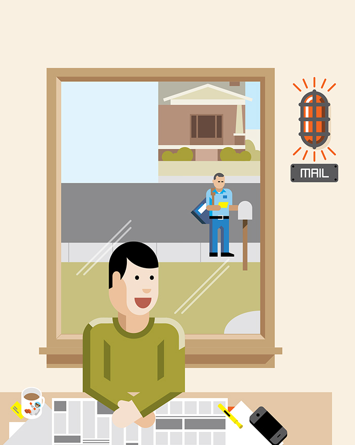
» Place a motion detector in your mailbox, and have it turn on a light and sound a chime whenever the box is opened.
» Add a contact sensor and an X10 Powerflash module to your garage door, to sound a chime if the door is left open for 5 minutes or more.
» Put a proximity tag in your teenager’s car, so that when they drive up, the porch light comes on and interior lights illuminate a path to their room
— or to the refrigerator.
As a home automation buff, I’ve used X10 Powerline control products for over 30 years. And although the technology has some shortcomings, I still believe X10 is the cheapest and fastest way to automate a home.
One of the most powerful additions to any X10 system is macro capability, in which a controller monitors the power line for trigger signals and responds by executing timed sequences of additional X10 commands. Unfortunately, commercial solutions for running X10 macros are lacking. One choice is Windows software that must run on a dedicated, always-on PC, and is incapable of defining macros with nesting or conditional logic. Another choice is standalone X10 controller modules such as the CM11a and CM15a, but I’ve found these unreliable and prone to frequent lock-ups.
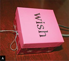
I have long wanted a small, reliable X10 macro module that I could program in C++, to maximize my options for coding and algorithm development. By standing on the shoulders of giants, I have created one — and the controller looks so good housed in a small jewelry box (Figure A) that my wife allows it to reside on our bedroom dresser.
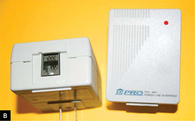
My X10 macro module has 2 main components: an Arduino microcontroller and a PSC05 (or equivalent TW523) X10 Powerline Interface Module (Figure B). The Arduino runs macros that you write in C++, calling in to a great open source code library of X10 transmit and receive commands. The PSC05 is a module designed to plug into a wall socket and translate in both directions, like a router, between X10 signals carried over a 120V AC power line and wires carrying standard 5V DC encoding, as used in digital electronics.
Jim Newell
On the low-voltage side, the module has a 4-conductor RJ11 jack for connecting it via telephone cable to X-10 control devices like home automation control consoles or wireless remote control receivers. But for this project, we’ll connect these 4 wires to the Arduino.
X10 PROTOCOL
To understand how this project works, you need to know the basics of X10. The X10 protocol was first developed in the late 1970s to support home automation commands carried over house wiring, so that appliances could be turned on and off and lamps dimmed or brightened remotely, with no need for dedicated control wires. X10 commands are injected onto the power line in a binary format, where a binary 1 is represented by a 1ms burst of a 120kHz signal, and a binary 0 is the lack thereof.
Because home power wiring is noisy, these signal bursts are injected only at the moments when the 60Hz (in the U.S.) AC power wave crosses 0, to maximize signal integrity. This happens 120 times per second (Figure C), and to accommodate artifacts from the 3-phase long-distance power grid transmission before it’s split into single-phase house current, each bit is transmitted redundantly 3 times, once for each phase.

To allow remote operation, each light and appliance unit in an X10 network has its own unique 8-bit address, and X10 command sequences consist of one or more unit addresses followed by a 4-bit code for the command that is requested. The command codes include on, off, dimmer, and brighter; query and response codes for checking device status; and special commands for switching on all lights or turning off all units that share the same house code.
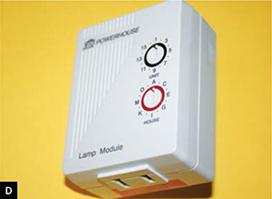
Device addresses break down into a 4-bit house code, usually designated by a letter A–P, and a 4-bit unit code designated by a number 1–16. You assign a unique address to a plug module by turning 2 dials on the front (Figure D), and then plug in a light or other device.
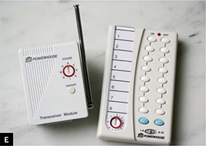
The module will listen on the power line for its address and respond to any commands sent to it. On the control side, Figure E shows a typical X10 wireless remote system. You plug the wireless receiver into the power line and turn the dial at the bottom of the remote to your house code. Then the remote’s 2 columns of buttons turn on and off your 16 devices, 1–8 with the slider switch to the left and 9–16 with the slider to the right.
PSC05 TRANSCEIVER WIRING
A PSC05 transceiver plugged into a wall socket detects every zero-crossing on our power line, and can read or transmit any X10 data associated with the crossing. Incremental work by Tom Igoe, BroHogan, and Creatrope has produced a free, open source Arduino library for interfacing with this device, letting us communicate via power line X10 as we wish. Using this library, we don’t need to know any X10 binary to program our macro module; we just need device addresses and desired functions.
The 4 connections to the PSC05 transceiver’s RJ11 phone jack are, in pin 1–4 order: zero-crossing detect, which reads high (5V) for 1 millisecond after each zero-crossing of the AC wave; ground reference (GND, 0V); data receive (RX) from the power line; and data transmit (TX) to the power line. The Arduino X10 library expects these to be connected to the Arduino’s digital I/O pin 2, ground, digital pin 4, and digital pin 5, respectively (Figure F).

START
ASSEMBLE THE HARDWARE
To break out the four RJ11 jack contacts on the PSC05 for connection to the Arduino, I plugged in a short phone cord, plugged the other end to a wall-mount phone jack receptacle, removed the receptacle cover, and wired the receptacle contacts to the Arduino headers using 3" lengths of 20-gauge wire (Figure G). Assuming standard phone wire color-coding, connect yellow to Arduino pin 2, green to GND, red to pin 4, and black to pin 5.

Mount the RJ11 receptacle onto the back of the Arduino using the double-sided adhesive patches that came with the receptacle (or double-stick foam tape), and snap or screw its cover back on, making sure the wire connections route nicely (Figure H). Your macro module is complete; now we’ll package it.

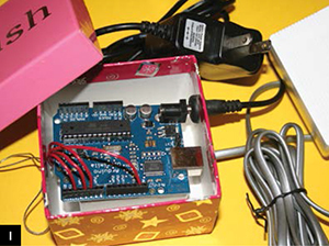
Place the module in your box and mark good locations for the phone cable and power cord to run through one side of the box, to plug into the phone receptacle and Arduino.
Drill 3/8" holes at the marked locations (after removing the module). Thread grommets over each cable, run the cables into the box, and push the grommets into the holes. Replace the module and plug in the cords (Figure I).
For a finishing touch, add rubber bumpers to the bottom of the box (Figure J, following page).

It looks so good housed in a small jewelry box that my wife allows it to reside on our bedroom dresser.
INSTALL THE SOFTWARE
Download and install the Arduino IDE (integrated development environment) software from arduino.cc/en/Main/Software, and if it doesn’t include a USB serial driver for the onboard FTDI chip, download and install the latest driver from ftdichip.com/drivers/vcp.htm. Launch the IDE and select your Arduino board type under the Tools → Board menu.
Download Creatrope’s X10 send/receive library from makezine.com/projects/x10-macro-module and copy the X10 folder to your Arduino libraries folder, the Contents/Resources/Java/libraries subfolder under your Arduino application folder (to navigate to the libraries folder, right-click on your Arduino application and select Show Package Contents). The X10 folder should now sit alongside EEPROM, Ethernet, and other included library folders.
TEST AND PROGRAM
Now comes the acid test: checking the Arduino’s X10 send and receive functions. Disconnect and remove the macro module from its box, and connect a USB cable between it and your computer. If you use a Diecimila, ensure that the plastic jumper near the square USB port is positioned on the 2 pins closest to the port, to supply power to the Arduino (this is not necessary with a Duemilanove). Connect a phone cable between the module’s RJ11 jack and the PSC05, and plug the latter into a wall outlet.
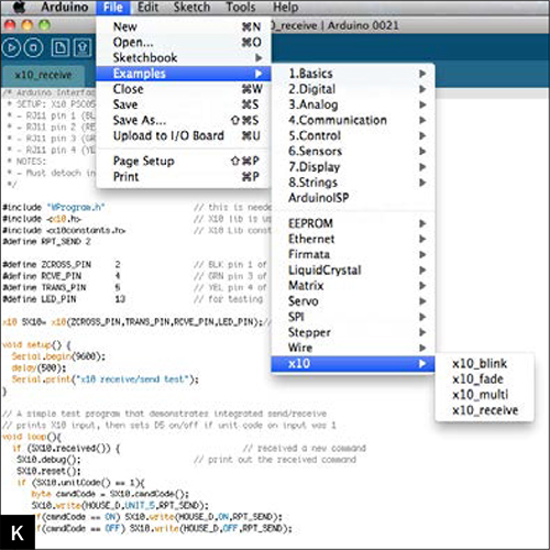
Restart the Arduino IDE and load the X10_receive example code by selecting it under the File → Examples → X10 menu (Figure K). Click the Verify button at the far left of the Arduino IDE menu bar, wait for the X10_receive code to compile, and then click the Upload button.
Open the Serial Monitor under Arduino IDE’s Tools menu. If you’ve done everything properly, commands and status messages from any X10 hardware you’ve plugged into your power line will appear in the Serial Monitor (Figure L).

We have reached the really fun part, where we exercise the Arduino assembly as a true X10 macro module. To begin, replace the loop function in the checkout example with new code that listens for macro triggers on the power line and responds by sending a sequence of X10 control commands. Figure M shows an example, and you can download the full C++ sketch at makezine.com/projects/x10-macro-module.

Open, compile, and upload it (or a variant) to your board from your computer as you did with the X10_receive code earlier, then reconnect the module to power and the PSC05. The macro module will begin code execution immediately, waiting for the proper X10 trigger before performing its magic.
This powerful macro sequence controls an outdoor motion detector (set to address A1), lamp module (set to B1), light switch module (C1), PowerHorn siren (D1), and IrrMaster sprinkler controller (E12). You can buy the sprinkler controller from homecontrols.com and everything else from X10.com.
The macro example waits for a signal from the motion detector, and then responds by turning on a lamp, sounding a siren, flashing the porch light, and activating sprinklers — to scare away raccoons and other intruders. After 30 seconds, the sprinklers and the lamp are turned off.
MAXIMIZE YOUR MACROS
If you’ve done any programming, even if you’re not a C++ whiz, you should be able to understand the event catcher loop code in Figure M, following the conditional phrase if (SX10.received()), and alter it to suit your needs. You will typically use if and == conditionals to check the X10 events received, the SX10.write function to send the messages that result, and the delay function to invoke wait periods. But of course, you have the entire C++ language at your disposal.

For instance, you can have the macro module sniff the power line for an indoor motion detector signal, and then turn on a series of lights that illuminates a path to the bathroom. This example is also included in the project code at makezine.com/projects/x10-macro-module, showing how multiple macros can coexist in the same Arduino sketch.
That’s about it. Reading the project code will give you a sense of how easy this really is. The possibilities for automation are limited only by your imagination.![]()
Jim Newell is an engineer/physicist at the NASA Jet Propulsion Laboratory in Pasadena, Calif.